EP0677335A2 - Procédé et dispositif pour détecter le debut d'inondation des atomiseurs à ultrason - Google Patents
Procédé et dispositif pour détecter le debut d'inondation des atomiseurs à ultrason Download PDFInfo
- Publication number
- EP0677335A2 EP0677335A2 EP95105027A EP95105027A EP0677335A2 EP 0677335 A2 EP0677335 A2 EP 0677335A2 EP 95105027 A EP95105027 A EP 95105027A EP 95105027 A EP95105027 A EP 95105027A EP 0677335 A2 EP0677335 A2 EP 0677335A2
- Authority
- EP
- European Patent Office
- Prior art keywords
- circuit
- frequency
- signal
- output
- resonance
- Prior art date
- Legal status (The legal status is an assumption and is not a legal conclusion. Google has not performed a legal analysis and makes no representation as to the accuracy of the status listed.)
- Withdrawn
Links
Images


Classifications
-
- B—PERFORMING OPERATIONS; TRANSPORTING
- B06—GENERATING OR TRANSMITTING MECHANICAL VIBRATIONS IN GENERAL
- B06B—METHODS OR APPARATUS FOR GENERATING OR TRANSMITTING MECHANICAL VIBRATIONS OF INFRASONIC, SONIC, OR ULTRASONIC FREQUENCY, e.g. FOR PERFORMING MECHANICAL WORK IN GENERAL
- B06B1/00—Methods or apparatus for generating mechanical vibrations of infrasonic, sonic, or ultrasonic frequency
- B06B1/02—Methods or apparatus for generating mechanical vibrations of infrasonic, sonic, or ultrasonic frequency making use of electrical energy
- B06B1/0207—Driving circuits
- B06B1/0223—Driving circuits for generating signals continuous in time
- B06B1/0238—Driving circuits for generating signals continuous in time of a single frequency, e.g. a sine-wave
- B06B1/0246—Driving circuits for generating signals continuous in time of a single frequency, e.g. a sine-wave with a feedback signal
- B06B1/0253—Driving circuits for generating signals continuous in time of a single frequency, e.g. a sine-wave with a feedback signal taken directly from the generator circuit
-
- B—PERFORMING OPERATIONS; TRANSPORTING
- B05—SPRAYING OR ATOMISING IN GENERAL; APPLYING FLUENT MATERIALS TO SURFACES, IN GENERAL
- B05B—SPRAYING APPARATUS; ATOMISING APPARATUS; NOZZLES
- B05B17/00—Apparatus for spraying or atomising liquids or other fluent materials, not covered by the preceding groups
- B05B17/04—Apparatus for spraying or atomising liquids or other fluent materials, not covered by the preceding groups operating with special methods
- B05B17/06—Apparatus for spraying or atomising liquids or other fluent materials, not covered by the preceding groups operating with special methods using ultrasonic or other kinds of vibrations
- B05B17/0607—Apparatus for spraying or atomising liquids or other fluent materials, not covered by the preceding groups operating with special methods using ultrasonic or other kinds of vibrations generated by electrical means, e.g. piezoelectric transducers
-
- B—PERFORMING OPERATIONS; TRANSPORTING
- B06—GENERATING OR TRANSMITTING MECHANICAL VIBRATIONS IN GENERAL
- B06B—METHODS OR APPARATUS FOR GENERATING OR TRANSMITTING MECHANICAL VIBRATIONS OF INFRASONIC, SONIC, OR ULTRASONIC FREQUENCY, e.g. FOR PERFORMING MECHANICAL WORK IN GENERAL
- B06B2201/00—Indexing scheme associated with B06B1/0207 for details covered by B06B1/0207 but not provided for in any of its subgroups
- B06B2201/40—Indexing scheme associated with B06B1/0207 for details covered by B06B1/0207 but not provided for in any of its subgroups with testing, calibrating, safety devices, built-in protection, construction details
-
- B—PERFORMING OPERATIONS; TRANSPORTING
- B06—GENERATING OR TRANSMITTING MECHANICAL VIBRATIONS IN GENERAL
- B06B—METHODS OR APPARATUS FOR GENERATING OR TRANSMITTING MECHANICAL VIBRATIONS OF INFRASONIC, SONIC, OR ULTRASONIC FREQUENCY, e.g. FOR PERFORMING MECHANICAL WORK IN GENERAL
- B06B2201/00—Indexing scheme associated with B06B1/0207 for details covered by B06B1/0207 but not provided for in any of its subgroups
- B06B2201/70—Specific application
- B06B2201/77—Atomizers
Definitions
- the invention relates to a method according to the preamble of claim 1 and an ultrasonic atomizer according to the preamble of claim 3.
- the invention is concerned with ultrasonic generators which are used in connection with ultrasonic vibrators which are used as atomizers for liquids. More specifically, the invention is concerned with a method and apparatus for reliably detecting the condition that the nebulizer has been flooded and cessation of atomization, and subsequently clearing the nebulizer of excess liquid and restoring stable operation to the resonance of the Ultrasonic transducer.
- ultrasonic transducers are typically made from a piezoelectric ceramic material that has electromechanical resonance effects that are typical of many piezoelectric devices. If such piezoelectric devices are operated at one of their natural resonance frequencies, an enormous improvement in the conversion of electrical energy into mechanical energy can be achieved if the resulting vibrations are amplified by using a suitable horn.
- a known application of ultrasonic waves is in the atomization of liquids, in particular fuel oil.
- a piezoelectric transducer or oscillator is constructed so that fuel in the form of a film of fuel can flow over an atomizing surface of its horn. If the ultrasonic transducer is on one of its natural resonance frequencies are excited with sufficient amplitude, the layer of fuel liquid covering the horn is thrown off its surface in the form of a mist of fine droplets.
- Such an ultrasonic vibrator or ultrasonic transducer is used as a device for atomizing the fuel in an oil burner, for example by replacing the high pressure atomizing nozzle that is usually used.
- a known method for determining the occurrence of flooding is to monitor whether the atomizer is no longer being driven at its chosen resonance frequency.
- the circuit required for this is generally only an extension of the circuit that is used by the resonance of the ultrasound transducer to find and follow this response.
- the resonant frequency of the ultrasonic transducer is found and this resonant frequency is followed by comparing the phase of the drive voltage with the phase of the resulting converter current and changing the drive frequency until the drive voltage and converter current are in phase that the atomizer is flooded when the driver voltage and the resulting converter current become out of phase.
- the ultrasound generator is typically caused to start frequency sweeping the ultrasound transducer over a certain frequency range until the resonance point is found again.
- the ultrasound generator typically begins with a frequency sweep for the ultrasound transducer over a specific frequency range in order to try to locate the amplitude maximum or amplitude minimum and to return to stable operation.
- Another known method for detecting atomizer flooding uses the reduction in "Q" of the resonance system that occurs when the atomizer is flooded. With this method, if the value of the converter current falls below a certain threshold value, it is assumed that the atomizer is excessively damped and is therefore flooded. Again, the ultrasound generator typically begins sweeping to try to rid the atomizer of excessive liquid and return to system resonance.
- a further method for the detection of atomizer flooding is known, in which the resonance quality "Q" of the resonance system is observed by evaluating the slope of the resonance curve.
- the snaps for this known method used resonance circuit not on a resonance frequency but continuously wobbles the excitation frequency between two frequency limits lying on both sides of the resonance frequency. If the resonance is sufficiently strong, the wobble is swept between the two frequency limits. If weak resonance is found, a wide frequency range is wobbled between the two frequency limits.
- the steepness of the resonance curve is determined by supplying the voltage drop across a resistor, through which the current of the driver output stage of the control circuit flows, directly to a comparator and on the other hand via a delay circuit.
- the resonance curve is too weak and the system switches over to the wide sweep range. If wobbling over the wide frequency range succeeds in throwing off non-atomized droplets, the edges of the resonance curve become steeper again and can be returned to wobbling over the narrow frequency range.
- the liquid to be atomized is flowed through a hole drilled axially through the length of the horn and exiting in the center of the horn surface. From here the liquid to be atomized flows radially outwards in a liquid film on the horn surface. As the fluid flows outward from the nodes in the middle of the horn, it is subjected to increased acceleration due to the ultrasonic vibrations that have a maximum at the extreme circumference of the horn surface. Before the liquid reaches the circumference of the horn, it usually reaches a point where the acceleration is sufficient to throw the liquid from the horn in the form of a mist of atomized liquid.
- the atomization therefore mainly occurs in a relatively narrow annular zone on the atomizer surface.
- the mean radius of this atomization zone with respect to the horn radius for the energy value and the efficiency of a given system is mainly determined by the viscosity of the liquid and its liquid throughput.
- the fuel throughput is tightly controlled, but the fuel viscosity can vary widely. It is therefore not uncommon for the fuel viscosity to be so high from time to time that at a certain energy value the fuel flows all the way to the edge of the horn surface and still does not receive enough energy to be repelled and atomized by the horn.
- a flooding mechanism which is much more difficult to identify, occurs when the atomizer's flooding begins slowly. This occurs, for example, when the volume of liquid is slowly moving toward a fixed flow rate or flow rate increases, the size of which exceeds the flow rate for which atomization can be maintained under the existing conditions with regard to viscosity and energy value. Since the use of a pulse damper in the fuel supply line of some oil burners is usually required to smooth out the flow pulses caused by the action of the fuel pump, this increasing increase in fuel flow towards a steady state flow rate occurs in such a system each time the system does so Fuel flow is started. This effect is due to the nature of the pulse damper, which acts as a temporary storage reservoir that stands in the way of any rapid changes in the fuel quantity delivery rate.
- the flow rate is lower than that which causes flooding under the existing fuel viscosity and energy value conditions.
- the atomization zone moves closer to the edge of the atomizer horn and can penetrate all the way to the edge of the horn.
- the nebulizer is at the limit of flooding.
- atomization begins to stop when liquid fuel begins to collect around the edge of the horn.
- This fuel increases the effective mass of the atomizer horn and this causes the natural resonant frequency of the ultrasound transducer to begin to decrease slightly.
- the ultrasound generator also called the excitation circuit here, and causes the ultrasound generator to lower its output frequency accordingly in order to adapt it to the new resonance.
- This process continues, with more fuel building up on the surface of the horn and the resonance frequency decreasing until atomization ceases completely and a hemispherical mass of fuel, which is held by standing waves, builds up and is held on the entire surface of the atomizer horn.
- the atomizer is now completely flooded. No atomization takes place.
- the flood detection methods described above are unable to detect this condition because the system is actually in resonance and the "Q" of the system is not unreasonably low.
- the only way to get rid of this large amount of excess fuel is either to shut down the system or to quickly drive the frequency to a very different value, such as the minimum frequency of the frequency range. In both cases, this eliminates the standing waves that hold the excess fuel and the fuel drops instantly.
- a method and a circuit arrangement for overcoming the problems described are to be made available, with which on the one hand the onset of a flood of an ultrasonic atomizer is reliably determined and on the other hand excess liquid is removed from a flooded ultrasonic atomizer and then a stable atomization at a selected transducer resonance frequency of the possible Transducer resonance frequencies is resumed.
- the frequency of the ultrasound generator or the excitation circuit is monitored according to the invention while it drives the atomizer at resonance, and according to the invention the small but relatively rapid drop in the natural resonance frequency is detected, which is caused by the accumulating liquid mass and has now been recognized as a circumstance always accompanying an occurring flood.
- Slow increases or decreases in resonance frequency such as those caused by temperature changes, are ignored, as are rapid frequency increases, such as those caused when, for example, an initial search is performed to locate the desired resonance frequency.
- the ultrasound transducer can be replaced with another one, which usually does not have exactly the same resonance frequency as the replaced ultrasound transducer, without affecting the ability of the circuit to detect flooding of the atomizer. This is possible because the absolute frequency is ignored during operation and only a frequency ratio of frequencies that are considered in a short time interval is monitored.
- the ultrasound generator is forced to the minimum frequency within its frequency range. This leads to an immediate breakdown of the standing wave structure, which can hold a large excess of fuel on the atomizing surface of the horn, allowing the excess fuel to fall off.
- the flood detection circuit sends a signal to a system controller that temporarily turns off the fuel pump and the fuel flow begins to decrease as the fuel pulse damper discharges. The ultrasound generator must now try to lock onto the selected resonance frequency of the atomizer.
- the commonly used method of frequency sweep often as an aid to shaking off excess liquid and as an aid to Localization of the resonance frequency is considered not to be used in the invention.
- This method is of little value when shaking off liquid, since only a very small fraction of the total time is allotted to the resonance point during the frequency sweep. Most of the time, states occur outside of resonance, where almost no mechanical energy is generated. Occasionally, a last single drop may stick to the edge of the horn, and it is possible that the action of the frequency sweep shakes this drop off. However, this is of no real use, since a single drop of liquid does not result in an excessive damping of the atomizer that the ultrasound generator could not find its resonance point.
- the frequency sweep method is also not an effective way to locate resonance.
- the normal feedback loop which allows the ultrasound generator or the excitation circuit to enter the resonance point, is disconnected. If a resonance point is detected during the frequency sweep, the frequency sweep circuit must be disconnected and then the feedback loop of the excitation circuit must be reactivated and stabilized very quickly. If this does not happen, the frequency sweep circuit runs beyond the desired resonance point and this is not determined.
- an excitation circuit concept is used that automatically converges to the desired resonance point of the ultrasound transducer without the need for a frequency sweep, provided that the ultrasound transducer is not excessively damped.
- an excitation circuit is used which is quite similar to the excitation circuit described in US Pat. No. 5,113,116.
- a PLL circuit with a very high loop gain is used to compare the phase of the converter drive voltage with the phase of the resulting converter current. The result of the comparison is used to change the frequency of the drive voltage until the drive voltage and the resulting converter current are locked in phase.
- the circuit has been optimized for snapping to a series resonance of the ultrasonic transducer.
- the circuit cannot snap to this resonance point, since the PLL circuit, which has been optimized for snapping to series resonance, is of course forced away from the parallel resonance point. If resonance is not detected or the atomizer is flooded, the drive frequency is reset to the lowest frequency in the desired range and the PLL circuit is given the opportunity to try again to find the desired resonance point without other help. This process is repeated until the liquid flow through the nebulizer has been reduced to a point where it is possible to determine and lock onto the series resonant frequency.
- Fig. 1 shows a block diagram of a circuit used to determine the onset of flooding of the ultrasonic transducer. This circuit is used in connection with and for controlling an ultrasonic generator or an excitation circuit, which is shown and explained later.
- the circuit shown in FIG. 1 is also called a frequency drop detector circuit here.
- the frequency drop detector circuit comprises a peak value detector 20 and an offset adder circuit 22. Their inputs are connected in common to a feed line 31, which is supplied with a signal, which will be explained later, which corresponds to the frequency of the ultrasound transducer.
- a non-inverting input of a comparator 26 is connected to the output of the peak detector 20.
- An inverting input of the comparator 26 is connected to the output of the offset adder circuit 22 via a low-pass filter 24.
- a monostable multivibrator in the form of a monoflop 28 is connected to the output of the comparator 26 and emits output pulses with a pulse duration of preferably 100 ms when it is triggered on the input side.
- the peak value detector 20 contains an operational amplifier 20-1, the non-inverting input of which is connected to the supply line 31 and the output of which, with the interposition of a diode 20-2, via a parallel connection of a capacitor 20-3 and one Resistor 20-4 is connected to ground on the one hand and to the non-inverting input of the comparator 26 on the other hand.
- the inverting input of operational amplifier 20-1 is connected to the connection point between capacitor 20-3 and diode 20-2.
- VCO voltage-controlled oscillator 1
- this voltage is in the range from 1 to 6 volts and is proportional to the drive frequency of the excitation circuit.
- a voltage of one volt or any voltage below it corresponds to the minimum frequency and a voltage of 6 volts corresponds to the maximum frequency of the selected operating frequency range of the excitation circuit.
- This voltage is supplied to the peak detector circuit 20.
- the capacitor 20-3 serves as a storage capacitor that can be discharged via the resistor 20-4.
- This circuit acts like a conventional peak value detector, the capacitor 20-2 of which stores the highest previously occurring value of the control voltage of the voltage-controlled oscillator 1.
- Resistor 20-4 slowly discharges storage capacitor 20-3 such that peak detector 20 can follow slow decreases in the control voltage of VCO 1 as caused by temperature changes of the ultrasonic transducer while relatively rapid decreases in control voltage of VCO 1 in the storage capacitor 20-3 are stored and the peak detector 20 cannot follow such rapid decreases.
- a discharge time constant of about 40 seconds is preferred as the optimum for particularly good operation.
- the instantaneous value of the VCO control voltage is also fed to the offset adding circuit 22, which adds a constant positive offset voltage to the VCO control voltage.
- This offset voltage represents the maximum short-term frequency drop that is allowed before the atomizer is considered to be flooded.
- the value of the offset voltage depends on many factors. In the illustrated Embodiment, a value of about 200 mV is preferred, which has been found to be optimal for good operation.
- the low pass filter 24 is provided to remove any noise.
- the output signal of the peak value detector 20 is naturally filtered by the storage capacitor 20-2.
- the drive frequency and thus the VCO control voltage on the feed line 31 are relatively constant.
- the output voltage of the peak value detector 20 in this case is identical to the VCO control voltage on the supply line 31.
- the peak detector 20 is able to follow slow changes in frequency and thus the VCO control voltage on the feed line 31 as may be caused by changes in operating temperature, changes in atomizer load due to changes in fuel, build-up of contaminants on the Atomizers, atomizer aging and the like. This is because the peak detector 20 naturally follows increases in the VCO control voltage of any rate of change and an adaptation to slow voltage drops occurs due to the slow discharge effect of the discharge resistor 20-4.
- the comparator 26 Under stable working conditions in the run-in state, the comparator 26 receives at its non-inverting input an output signal 21 of the peak value detector 20 and at its inverting input a filtered signal 25 from the output of the offset adder circuit 22, which is 200 mV higher than the signal which is on the non-inverting input of the comparator 26 occurs. This leads to a signal state "LOW" at the output 27 of the comparator 26.
- the output signal of the comparator 26 is fed to the monoflop 28, the output 29 of which is normally in the "LOW” state.
- the monoflop 28 receives a short positive signal transition at its input 27, its output 29 changes to the "HIGH” state for a period of approximately 100 ms. The purpose and reason for this short positive output pulse will be described below. For now, it should be noted that an atomizer that has been run in Condition driven, no output signal is generated at the output of the monoflop 28.
- the above conditions change when the atomizer begins to flood.
- the additional liquid mass on the atomizer horn causes the resonance frequency to start to drop somewhat.
- the excitation circuit is still locked onto the resonance frequency of the atomizer and therefore sets the drive frequency so that it is adapted to the new, lower resonance frequency.
- the VCO control voltage on the supply line 31 therefore begins to decrease since the VCO 1 has to be operated at a somewhat lower frequency.
- the output signal 21 of the peak value detector 20 does not initially follow the decrease in the VCO control voltage because the discharge resistor 20-4 cannot discharge the storage capacitor 20-3 sufficiently quickly and because the diode 20-2 prevents the operational amplifier 20-1 from storing the storage capacitor 20 -4 to lower voltage.
- the output signal 23 of the offset adder circuit 22 follows the VCO control voltage as it decreases, the output of the offset adder circuit 22 always being kept at a value of 200 mV above the instantaneous value of the VCO control voltage.
- a relatively rapid reduction in the resonance frequency at the beginning of the atomizer flooding which corresponds to a reduction in the VCO control voltage of more than 200 mV, leads to the signal 25 at the inverting input of the comparator 26 taking a lower value than the signal 21 at the Non-inverting input of the comparator 26.
- the output 27 of the comparator 26 changes to the "HIGH" state and the monoflop 28 is triggered, which produces a positive pulse with a duration of 100 ms at its output 29. This pulse, which is generated whenever the atomizer begins to flood, is used to initiate a release from this flood condition.
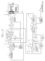
- FIG. 2 shows the basic flood detector circuit shown in FIG. 1 in combination with a block diagram of a preferred one Excitation circuit and with an additional circuit device that clears a flooded atomizer of excess liquid and returns to stable operation at resonance.
- the circuit arrangement added to the frequency drop detector circuit in FIG. 2 comprises a switch 30 which is connected in parallel with the discharge resistor 20-4 and is controlled by the output signal of the monoflop 28, a voltage clamping circuit 32 which is connected between the output 23 of the offset adder circuit 22 and ground , and a second monostable multivibrator in the form of a second monoflop 34, which is used to control an external liquid pump.
- the second monoflop 34 is triggered by the output pulse of the first monoflop 28. It is a repeatable monoflop that produces an output pulse of approximately 10 s.
- the switch 30 is shown schematically in FIG. 2 as a mechanical switch. However, it can take the form of a semiconductor switch, for example a switching transistor.
- the voltage clamp circuit 32 acts similarly to a Zener diode with a Zener voltage of 6.0 volts. It prevents the output of the offset adder 22 from rising above 6.0 volts.
- FIG. 2 a slightly modified version of the ultrasonic generator shown in FIG. 1 of US Pat. No. 5,113,116 is used.
- the modification consists in the omission of a threshold amplifier 11 in FIG. 1 of US Pat. No. 5,113,116 and in the addition of a switch 33 to the ultrasound generator shown in FIG. 1 in US Pat. No. 5,113,116.
- An ultrasonic transducer 5 for generating ultrasonic vibrations is supplied with electrical excitation energy from the excitation circuit via a transformer 4.
- the excitation circuit comprises the voltage-controlled oscillator 1, the output signal of which is fed to the primary side of the transformer 4 via a power amplifier 3.
- the oscillator voltage which arises at the output 2 of the VCO 1 is fed to a first input 18 of a phase comparator 13 via a phase shifter 17, which causes a phase shift of -90 °.
- Its second input 10 is fed via a low-pass filter 9 with a linear phase response, a voltage which arises via a current sensing resistor 7 and corresponds to the current flowing through the converter 5.
- phase of the drive voltage output by the excitation circuit and the phase of the converter current flowing through the converter 5 are thus compared with one another in the phase comparator 13.
- a signal corresponding to the phase deviation arises at the output 14 of the phase comparator 13 and is supplied to an input 16 of the VCO 1 by an integrating loop filter 15 with high amplification. If one assumes that the frequency of the VCO 1 tracks the resonance frequency of the transducer 5, the VCO control voltage corresponds to the respective instantaneous oscillation frequency of the transducer 5.
- the threshold value amplifier 11 is not included in FIG. 1 of the US patent mentioned.
- the threshold amplifier 11 serves to block the input signal 10 supplied to the phase comparator 13 by the low-pass filter 9 when the current through the converter 5 is very low because the ultrasound generator is operated in close proximity to a parallel resonance .
- this has proven to be unnecessary and undesirable because the situation is temporary Open loop is generated when the frequency of the ultrasound generator passes through the parallel resonance frequency of the ultrasound transducer 5.
- the generator circuit used for the present invention is designed so that it snaps onto the series resonance frequency of the ultrasound transducer 5 and is therefore naturally forced away from the parallel resonance frequency. That is, for all frequencies below the parallel resonance, the present circuit snaps to the series resonance frequency, and for all frequencies above the parallel resonance, the present circuit is pushed to the upper frequency limit of the VCO 1.
- the second modification compared to FIG. 1 of the aforementioned US patent consists in the addition of the switch 33, via which the inverting input of the integrator 15-4, 15-5 and 15-6 of the loop filter 15 with a positive source Voltage is connected that is higher than the voltage that is normally present at the non-inverting input of the loop filter 15.
- This switch 33 is also shown as a mechanical switch for the sake of simplicity, but may preferably have the form of a switching transistor or another semiconductor switch device.
- the switch 33 is under the control of the output 29 of the monoflop 28 such that the switch 33 is closed for the duration of a 100 ms output pulse of the monoflop 28.
- this circuit feature is as follows: when a flood condition is detected, the monoflop 28 output pulse temporarily closes switch 33, causing the output signal 16 of the integrating loop filter 15, which forms the VCO control voltage, to be driven to its minimum value.
- the pulse duration 100 ms of the pulse generated by the monoflop 28 is selected so that the integrating loop filter 15 is given sufficient time to reach its minimum output voltage.
- the output frequency of the excitation circuit is quickly reset to the minimum frequency of the predetermined frequency range of the VCO 1 to make the excitation circuit start prepare a new search for the resonance frequency of the ultrasonic transducer 5.
- the VCO control voltage of the excitation circuit is supplied to the supply line or the input 31 of the peak value detector 20 and the offset adder circuit 22, as has already been described above.
- the storage capacitor 20-3 of the peak detector 20 must discharge quickly in order that the output 21 of the peak value detector 20 again adapts to the VCO control voltage in order to enable the output 27 of the comparator 26 to return to a "LOW" state before a new resonance search. This is achieved by the switch 30, which is activated by the output signal of the monoflop 28.
- the storage capacitor 20-3 is rapidly discharged at the same time that the VCO control voltage and thus the frequency of the sputter generator are controlled to their minimum value.
- the PLL circuit naturally causes, as already mentioned above, that the ultrasonic generator is controlled to the upper frequency limit and is permanently "parked” there. It must now be assumed that the ultrasound generator comes into such a situation from time to time, and it must be able to free itself from it. Such a relief is provided by the voltage clamp circuit 32.
- the maximum VCO control voltage that the VCO 1 can handle in the existing embodiment is 6.0 volts
- the supply voltage for the integrator 15-6 of the loop filter 15 is somewhat higher to ensure that the output of integrator 15-6 can span the full range of VCO control voltage.
- the output signal of the integrator 15-6 or the VCO control voltage will therefore attempt to reach the upper limit to increase the supply voltage of the integrator 15-6, which is slightly higher than 6.0 volts, as already noted.
- the output 21 of the peak detector 20 follows this rise.
- the output of the offset adder circuit 22 is limited to a maximum voltage of 6.0 volts by the action of the voltage clamp circuit 32. Since the non-inverting input (21) of the comparator 26 is now more positive than its inverting input (25), the comparator 26 now reacts by changing its output 27 to a "HIGH" state. This triggers monoflop 28. As a result, the output frequency of the ultrasound generator is reset to the minimum value within its frequency range, just as if the atomizer had been flooded.
- the repeatedly triggerable monoflop 34 is used, which can be triggered by the output signal of the first monoflop 28.
- the pulse length of the second monoflop 34 depends on a number of factors. A pulse length of 10 seconds has proven to be optimal.
- the purpose of the second monoflop 34 is to send a command through its output 35 to a fuel pump controller to temporarily stop the pump during a resonance search.
- the second monflop 34 When a flood condition is determined and the first monoflop 28 generates a pulse of 100 ms pulse length to reset the frequency of the ultrasound generator to the minimum value, the second monflop 34 is also triggered and the output signal at its output 35 causes the fuel pump is stopped for 10 s. If a flooding of the nebulizer is found again within this time during a resonance search, the monoflop 34 is triggered again and the already started period of 10 s is extended by a further 10 s. The time period of 10 s gives the system enough time to stabilize itself after a successful resonance search before the fuel flow is started again.
- the flood detector circuit can reliably detect the onset of ultrasonic nebulizer flooding, can reset the ultrasonic generator frequency to the lower frequency limit to allow the ultrasonic generator to begin a new resonance search, and can signal this condition to a fuel pump control direction. so that pump operation can be temporarily stopped. And if the resonance search is unsuccessful and the ultrasound generator is forced to the upper frequency limit, the flood detector circuit can also determine this and reset the generator frequency to the lower frequency limit in order to start a further resonance search.
- FIG. 3 shows the ultrasound generator frequency as a function of time, starting with a system in normal resonance mode that is flooded and then recovers from the flooding condition.
- Section A of the curve shown in Fig. 3 shows that the ultrasonic nebulizer is flooded.
- Section B shows the generator how to search for a resonance but cannot find any resonance point.
- Sections C and D are similar to section B, but a strongly damped resonance is temporarily found as the fuel flow decreases.
- Section E shows how the ultrasonic generator temporarily stops at a frequency that is lower than the normal resonance frequency due to the load of fuel, but the ultrasonic atomizer is still flooded with fuel and the system returns to the minimum frequency.
- Section F again shows that resonance has been found, but is now in a state where the fuel flow has been almost completely stopped and the system is able to clear the ultrasonic atomizer of excess fuel and return to normal operation.
- the curve shown there begins with a state in which an ultrasonic generator drives its ultrasonic atomizer at resonance 50 and normal atomization takes place.
- flooding begins and the decrease in the resonance frequency is shown as a downward inclined curve part 52.
- the resonant frequency decreases rapidly enough that the VCO control voltage at point 53 has decreased by 200 mV, which triggers the monoflop 28 and causes the ultrasound generator to be forced to its minimum frequency at 54, ensuring that any excess fuel, which is held on the atomizer horn drops, as previously explained.
- the monoflop 34 is also triggered and sends a signal to the fuel pump control device which shuts off the fuel flow.
- the VCO 1 which had previously been kept at 55 at its minimum frequency, is released and can begin to search for a resonance point.
- the frequency of the ultrasound generator increases linearly at 56, under the control of the PLL circuit of the ultrasound generator. No frequency sweeping circuit or wobble circuit is used or required. Due to the fact that the fuel flow is still relatively high because the fuel pulse damper is discharging, far too much fuel is still flowing through the atomizer horn for any resonance to be detected.
- This state also leads to a phase relationship between the atomizer voltage and the atomizer current, which causes the phase comparator 13 of the excitation circuit to drive the VCO control voltage to a higher value and the frequency then increases linearly with a slew rate which is only controlled by the loop time constant, which is primarily determined by the resistance value of resistor 15-3 and the capacitance value of capacitor 15-5.
- the voltage clamp circuit 32 triggers the comparator 26 to change its output signal, which in turn triggers the monoflop 28, whose output signal in turn resets the nebulizer generator to the minimum frequency to start another resonance search .
- the fuel flow has decreased somewhat.
- the frequency of the atomizer generator rises linearly in the region 59 as before, but then stops temporarily at 60, since a strongly damped resonance frequency is found that is much lower than the normal resonance frequency.
- the PLL circuit of the ultrasound generator cannot latch onto this unstable point and will soon be driven upwards again to higher frequencies in region 61 until the point of maximum frequency is reached at 62 and the ultrasound generator is reset to minimum frequency again.
- the VCO 1 is released again and another resonance search begins with increasing frequencies.
Landscapes
- Engineering & Computer Science (AREA)
- Mechanical Engineering (AREA)
- Special Spraying Apparatus (AREA)
Applications Claiming Priority (2)
| Application Number | Priority Date | Filing Date | Title |
|---|---|---|---|
| DE4412900 | 1994-04-14 | ||
| DE4412900A DE4412900C2 (de) | 1994-04-14 | 1994-04-14 | Verfahren und Vorrichtung zum Feststellen des Einsetzens einer Überflutung eines Ultraschallzerstäubers |
Publications (2)
| Publication Number | Publication Date |
|---|---|
| EP0677335A2 true EP0677335A2 (fr) | 1995-10-18 |
| EP0677335A3 EP0677335A3 (fr) | 1997-05-21 |
Family
ID=6515406
Family Applications (1)
| Application Number | Title | Priority Date | Filing Date |
|---|---|---|---|
| EP95105027A Withdrawn EP0677335A3 (fr) | 1994-04-14 | 1995-04-04 | Procédé et dispositif pour détecter le debut d'inondation des atomiseurs à ultrason. |
Country Status (3)
| Country | Link |
|---|---|
| US (1) | US5588592A (fr) |
| EP (1) | EP0677335A3 (fr) |
| DE (1) | DE4412900C2 (fr) |
Cited By (2)
| Publication number | Priority date | Publication date | Assignee | Title |
|---|---|---|---|---|
| WO2009056189A1 (fr) * | 2007-11-02 | 2009-05-07 | Braun Gmbh | Circuiterie et procédé d'alimentation d'une charge capacitive |
| CN104549829A (zh) * | 2014-12-16 | 2015-04-29 | 摩易国际股份有限公司 | 智能型雾化器的控管方法 |
Families Citing this family (17)
| Publication number | Priority date | Publication date | Assignee | Title |
|---|---|---|---|---|
| IL121414A (en) * | 1997-07-28 | 2001-11-25 | Green Clouds Ltd | Ultrasonic device for atomizing liquids |
| SE9804484D0 (sv) | 1998-12-22 | 1998-12-22 | Siemens Elema Ab | Förfarande för avsökning och inställning av en resonansfrekvens samt en tuner |
| DE10008937A1 (de) * | 2000-02-25 | 2001-08-30 | Philips Corp Intellectual Pty | Elektrischer Schaltkreis zur Ansteuerung von piezoelektrischen Antrieben |
| DE10053826A1 (de) * | 2000-10-30 | 2002-05-16 | Generis Gmbh | Vorrichtung zum Auftragen von zerstäubten Fluiden |
| GB0129139D0 (en) * | 2001-12-05 | 2002-01-23 | Sra Dev Ltd | Ultrasonic generator system |
| DE10323063A1 (de) | 2003-05-20 | 2004-12-09 | Endress + Hauser Gmbh + Co. Kg | Verfahren zur Füllstandsmessung |
| JP2006105620A (ja) * | 2004-09-30 | 2006-04-20 | Advantest Corp | 電源装置及び試験装置 |
| US7412215B1 (en) * | 2005-06-03 | 2008-08-12 | Rf Micro Devices, Inc. | System and method for transitioning from one PLL feedback source to another |
| FR2903331B1 (fr) * | 2006-07-07 | 2008-10-10 | Oreal | Generateur pour exciter un transducteur piezoelectrique |
| RU2465965C1 (ru) * | 2011-10-06 | 2012-11-10 | Общество с ограниченной ответственностью "Центр ультразвуковых технологий АлтГТУ" | Способ управления процессом ультразвукового распыления |
| US9242263B1 (en) * | 2013-03-15 | 2016-01-26 | Sono-Tek Corporation | Dynamic ultrasonic generator for ultrasonic spray systems |
| AU2014316769B2 (en) | 2013-09-09 | 2018-12-06 | Omnimist, Ltd. | Atomizing spray apparatus |
| CA3019194A1 (fr) | 2016-03-30 | 2017-10-05 | Marine Canada Acquisition Inc. | Appareil de chauffage de vehicule et commandes associees |
| CN111855823B (zh) * | 2020-07-22 | 2024-12-06 | 上海岩联工程技术有限公司 | 一种超声换能器快速激励装置及控制方法 |
| US11942951B2 (en) * | 2022-01-31 | 2024-03-26 | Dwellwell Analytics, Inc. | Conditional track and hold amplifier |
| CN114669436B (zh) * | 2022-03-17 | 2024-02-02 | 重庆大学 | 调频驱动电路、调频驱动方法、驱动装置 |
| DE102022134059A1 (de) * | 2022-12-20 | 2024-06-20 | Karl Storz Se & Co. Kg | Ultraschallgenerator zum Zuführen einer elektrischen Leistung, Lithotripsievorrichtung zum Zertrümmern von Körpersteinen und Verfahren zum Betreiben und/oder Regeln einer Lithotripsievorrichtung |
Family Cites Families (11)
| Publication number | Priority date | Publication date | Assignee | Title |
|---|---|---|---|---|
| US3400892A (en) * | 1965-12-02 | 1968-09-10 | Battelle Development Corp | Resonant vibratory apparatus |
| DE2129665C3 (de) * | 1970-06-30 | 1981-02-12 | Siemens Ag, 1000 Berlin Und 8000 Muenchen | Vorrichtung zum Zerstäuben von Flüssigkeiten mit einem piezoelektrisch angeregten Schwingungssystem |
| CA930005A (en) * | 1971-06-15 | 1973-07-10 | Siemens Aktiengesellschaft | Piezoelectric vibrators |
| US3869666A (en) * | 1973-12-26 | 1975-03-04 | Julian Saltz | Maximum slope detectors |
| JPS5610792A (en) * | 1979-07-06 | 1981-02-03 | Taga Denki Kk | Method and circuit for driving ultrasonic-wave converter |
| US4469974A (en) * | 1982-06-14 | 1984-09-04 | Eaton Corporation | Low power acoustic fuel injector drive circuit |
| US4642581A (en) * | 1985-06-21 | 1987-02-10 | Sono-Tek Corporation | Ultrasonic transducer drive circuit |
| DE3534853A1 (de) * | 1985-09-30 | 1987-04-02 | Siemens Ag | Verfahren zum betrieb eines ultraschallzerstaeubers zur fluessigkeitszerstaeubung |
| EP0340470A1 (fr) * | 1988-05-06 | 1989-11-08 | Satronic Ag | Procédé et circuit pour exciter un transducteur par ultrasons, et leur utilisation pour l'atomisation d'un liquide |
| US5113116A (en) * | 1989-10-05 | 1992-05-12 | Firma J. Eberspacher | Circuit arrangement for accurately and effectively driving an ultrasonic transducer |
| DE4210705C2 (de) * | 1992-04-01 | 1995-10-19 | Grieshaber Vega Kg | Frequenz-Spannungswandler für Vibrations-Füllstand-Detektoren sowie Verfahren zur Umwandlung eines Eingangssignals in ein die Eingangssignalfrequenz repräsentierendes Ausgangssignal |
-
1994
- 1994-04-14 DE DE4412900A patent/DE4412900C2/de not_active Expired - Fee Related
-
1995
- 1995-04-04 EP EP95105027A patent/EP0677335A3/fr not_active Withdrawn
- 1995-04-13 US US08/421,685 patent/US5588592A/en not_active Expired - Fee Related
Cited By (3)
| Publication number | Priority date | Publication date | Assignee | Title |
|---|---|---|---|---|
| WO2009056189A1 (fr) * | 2007-11-02 | 2009-05-07 | Braun Gmbh | Circuiterie et procédé d'alimentation d'une charge capacitive |
| US8456248B2 (en) | 2007-11-02 | 2013-06-04 | Braun Gmbh | Circuit arrangement and method for supplying a capacitive load |
| CN104549829A (zh) * | 2014-12-16 | 2015-04-29 | 摩易国际股份有限公司 | 智能型雾化器的控管方法 |
Also Published As
| Publication number | Publication date |
|---|---|
| DE4412900A1 (de) | 1995-10-26 |
| EP0677335A3 (fr) | 1997-05-21 |
| DE4412900C2 (de) | 2000-04-27 |
| US5588592A (en) | 1996-12-31 |
Similar Documents
| Publication | Publication Date | Title |
|---|---|---|
| EP0677335A2 (fr) | Procédé et dispositif pour détecter le debut d'inondation des atomiseurs à ultrason | |
| DE69114732T2 (de) | Einrichtung zur Überwachung des Betriebs eines Mikroprozessorsystems oder dergleichen. | |
| DE3686574T2 (de) | Vorrichtung zum zertaeuben von kraftstoff durch ultraschall fuer brennkraftmaschinen. | |
| DE3625149A1 (de) | Verfahren zur phasengesteuerten leistungs- und frequenzregelung eines ultraschallwandlers sowie vorrichtung zur durchfuehrung des verfahrens | |
| EP1540291B1 (fr) | Capteur de niveau a oscillations | |
| DE3783748T2 (de) | Antriebsgeraet fuer ein ultraschallhorn und verfahren mit aktivem frequenznachlauf. | |
| EP0340470A1 (fr) | Procédé et circuit pour exciter un transducteur par ultrasons, et leur utilisation pour l'atomisation d'un liquide | |
| DE3734146A1 (de) | Kristalloszillatorschaltung zum schnellen, verlaesslichen anlauf | |
| DE3312964A1 (de) | Verfahren und vorrichtung zum ermitteln der lage eines zielobjekts | |
| DE3231259C2 (de) | Schaltungsanordnung zur Drehzahlüberwachung | |
| DE4322388C2 (de) | Schaltungsanordnung zum sicheren Anschwingen von Ultraschalldesintegratoren | |
| CH678404A5 (fr) | ||
| EP0303944A1 (fr) | Procédé et circuit pour l'excitation d'un vibrateur ultrasonore et leur application à la pulvérisation d'un liquide | |
| EP0421439B1 (fr) | Pulvérisateur à ultrason | |
| DE2000332A1 (de) | Steueranordnung | |
| DE3644811C2 (fr) | ||
| EP2390634B1 (fr) | Dispositif de fonctionnement d'une unité pivotante d'un résonateur à vibrations | |
| DE3013964A1 (de) | Ultraschallgenerator | |
| DE69817897T2 (de) | Phasenregelkreis | |
| CH670343A5 (fr) | ||
| DE3810669C2 (de) | Vorrichtung zur Überwachung des Pegelstandes einer Flüssigkeit | |
| CH674074A5 (fr) | ||
| DE3720501A1 (de) | Phasengerecht startender, spannungsgesteuerter oszillator mit genauem tastverhaeltnis | |
| DE4200194C2 (de) | Schwingförderanordnung | |
| DE102016223337B4 (de) | Schnellstart-kristalloszillator mit geringer variation |
Legal Events
| Date | Code | Title | Description |
|---|---|---|---|
| PUAI | Public reference made under article 153(3) epc to a published international application that has entered the european phase |
Free format text: ORIGINAL CODE: 0009012 |
|
| AK | Designated contracting states |
Kind code of ref document: A2 Designated state(s): AT BE DE DK ES FR GB IT PT SE |
|
| PUAL | Search report despatched |
Free format text: ORIGINAL CODE: 0009013 |
|
| AK | Designated contracting states |
Kind code of ref document: A3 Designated state(s): AT BE DE DK ES FR GB IT PT SE |
|
| STAA | Information on the status of an ep patent application or granted ep patent |
Free format text: STATUS: THE APPLICATION IS DEEMED TO BE WITHDRAWN |
|
| 18D | Application deemed to be withdrawn |
Effective date: 19970501 |