EP0677385A1 - Machine à imprimer, en particulier machine d'impression au tampon - Google Patents
Machine à imprimer, en particulier machine d'impression au tampon Download PDFInfo
- Publication number
- EP0677385A1 EP0677385A1 EP95105354A EP95105354A EP0677385A1 EP 0677385 A1 EP0677385 A1 EP 0677385A1 EP 95105354 A EP95105354 A EP 95105354A EP 95105354 A EP95105354 A EP 95105354A EP 0677385 A1 EP0677385 A1 EP 0677385A1
- Authority
- EP
- European Patent Office
- Prior art keywords
- tampon
- cliché
- machine according
- printed material
- guide element
- Prior art date
- Legal status (The legal status is an assumption and is not a legal conclusion. Google has not performed a legal analysis and makes no representation as to the accuracy of the status listed.)
- Withdrawn
Links
Images

Classifications
-
- B—PERFORMING OPERATIONS; TRANSPORTING
- B41—PRINTING; LINING MACHINES; TYPEWRITERS; STAMPS
- B41F—PRINTING MACHINES OR PRESSES
- B41F17/00—Printing apparatus or machines of special types or for particular purposes, not otherwise provided for
- B41F17/001—Pad printing apparatus or machines
Definitions
- the invention relates to a printing press that applies a print image applied to a print head (tampon) to the printed matter.
- This printing machine is known in particular as a tampon printing machine.
- the conventional tampon printing machines are constructed as follows. A cliché slide moves relative to a color system on it. When these two parts move linearly towards each other, the paint is stripped away by a scraper. The cliché features recesses in the form of the geometry to be printed. In these depressions, the paint cannot be stripped back by the scraper. When the cliché has completed the linear movement to the color system, the color is on the now exposed cliché surface in the recessed print image. This paint now dries slightly on the air side.
- a rubber foam element called a tampon is positioned perpendicular to the cliché surface.
- This tampon now moves to the color print image on the cliché.
- the tampon is pressed onto the cliché. Since the ink is slightly dry on the surface, it adheres better to the tampon than in the cliché recess.
- the tampon now moves linearly away from the cliché.
- the cliché runs linearly under the color system. There is no longer any cliché positioned under the tampon.
- the tampon is pressed onto the print material by a further linear process, which is positioned on one level under the cliché slide.
- conventional pad printing machines DE-PS 19 23 374)
- the movement of the print head and the ink plate holder is achieved with a pneumatic drive and linear axes or electromechanically with an electric motor and cam control. The movements are set and cannot be changed during the printing process.
- the height of the printed matter must be positioned exactly under the tampon and must not vary in height with a machine setting.
- the force that the print head exerts on the print material, and on which the print quality depends, is determined and set by the position of the tampon and the print material.
- the invention has for its object to provide a machine of the type described in the introduction, in which the positional positioning, in particular with regard to the distance of the printed matter from the print head, is not critical and can be varied to a certain extent.
- the image or font to be printed is selected using an input device and applied to the tampon by the paint spray head.
- the ink is then printed onto the print material using the tampon and the set contact pressure.
- the advantages of direct spraying with the ink jet head are the flexible pressure piece height and mechanical printing with a desired printing force, which increases the print quality.
- the machine according to the invention is designed for printing on parts using a tampon.
- the advantages of the working process of this machine such as the automatic adjustment of the tampon stroke to the height of the material to be printed and the electronically adjustable tampon contact pressure, are combined with the freely programmable axis movements.
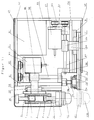
- the tampon printing machine is constructed as follows: The plates 51, 52, 53, 54 and 55 serve as the base body and frame. The plates 51 and 54 are connected to one another via the bearing block 56. The motor holders 61, 63 are fastened to the plates 51, 54.
- the machine has a separate box for the motor control 81 and a cover 57 as a cover to the outside.
- the tampon printing machine consists of two mutually perpendicular guide rails 31, 32 on which linear carriages 20, 21 move.
- the linear carriages 20, 21 are driven by drivers 33, 34 and ball screw nuts 35, 36 and ball screw spindles 37, 38 by means of toothed belt drives 65, 66 of electric motors 61, 62, which are fastened to motor holders 63, 64.
- the cliché holder 71 is fastened to the horizontal linear slide 21 and the cliché 72 is clamped thereon.
- the ink fountain 73 is fixed on the plate 72 with the holder 74 and pressed onto the plate via the cover 75 and hold-down device 76.
- the tampon guide element 41 is attached to the vertical linear slide 20.
- the linear drives are precisely positioned using encoders at the end positions of the movements and incremental encoders on the motors.
- the movement of the linear slide 21 is determined in both end positions by stops.
- the movement of the linear slide 20 takes place in the upper end position against the stop.
- the lower position, which is the printing position, is recognized via the light barrier 18 and positioned via the motor control 81.
- the printing machine in particular the pad printing machine, is used as follows:
- the machine is positioned in relation to the parts to be printed as follows.
- the linear axis 20 for the movement of the tampon is aligned with the print material.
- the pressure feed and position must be selected so that the cliché slide 71 can be extended and retracted without colliding with the printed matter or other devices.
- the machine is now attached to the designated brackets on the base.
- the operating cycle of the machine is started by pressing the start button on the front of the machine, by pressing the foot switch or by an external signal.
- the cliché 72 moves to the front position 101.
- the printed image which was introduced into the cliché 72 and which had previously been located under the ink fountain 73 is guided in front of the ink reservoir 73 and under the tampon 19.
- the edge of the ink cup 73 strips off the color during this movement, except in the depressions of the printed image of the plate 72.
- the tampon 19 moves onto the plate 72 and receives the printing ink in the plate recesses. Now the Tamon 19 moves away from the cliché 72 upwards and the cliché 72 moves back to the rear end position.
- the tampon 19 moves in the direction of the front position 102 onto the printed material.
- the tampon 19 springs into the tampon guide element 41, whereby an increase in force from tampon to printed material has the effect when moving on, since the spring (6) is compressed during the further movement and the spring force increases on the tampon .
- the light barrier 18 in this case gives a signal from the motor control 81.
- the electric motor 61 for the pad guide carriage approach continues to rotate the previously programmed number of increments until the desired pad end position 102 and the pad pressure force connected via the spring force increase is achieved. The color is passed. Now the tampon 19 moves away from the printed matter into its upper end position. This completes the printing process.
- the hold-down device 76 is loosened and removed.
- the holder 74 is removed.
- the plate 72 is pulled out of the plate holder 71.
- the ink cup 73 is now streaked away from the cliché and care is taken that the color runs into the container provided.
- the cliché 72 is cleaned.
- the cliché 72 is pushed into the cliché holder 71.
- the clamping device is rotated until the cliché 72 is fixed.
- the ink cup 73 is placed on the plate 72 and positioned with the holder 74.
- the color is filled in.
- the lid 75 is put on.
- the hold-down device 76 is placed on the cover 75 and rotated until the contact pressure of the color top 73 ensures that the paint is stripped off properly. This can be checked by moving the cliché slide 21.
- the hold-down device 76 is loosened and removed for refilling the paint.
- the cover 75 is removed. Now the color can be refilled.
- the cover 75 is replaced and the hold-down device 76 is positioned on it.
- the contact pressure is now set and checked by actuating the plate slide 21, so that the ink is completely stripped off the ink cup 73.
Landscapes
- Printing Methods (AREA)
Applications Claiming Priority (2)
| Application Number | Priority Date | Filing Date | Title |
|---|---|---|---|
| DE19944412599 DE4412599C2 (de) | 1994-04-13 | 1994-04-13 | Druckmaschine, insbesondere Tampondruckmaschine |
| DE4412599 | 1994-04-13 |
Publications (1)
| Publication Number | Publication Date |
|---|---|
| EP0677385A1 true EP0677385A1 (fr) | 1995-10-18 |
Family
ID=6515208
Family Applications (1)
| Application Number | Title | Priority Date | Filing Date |
|---|---|---|---|
| EP95105354A Withdrawn EP0677385A1 (fr) | 1994-04-13 | 1995-04-08 | Machine à imprimer, en particulier machine d'impression au tampon |
Country Status (2)
| Country | Link |
|---|---|
| EP (1) | EP0677385A1 (fr) |
| DE (1) | DE4412599C2 (fr) |
Cited By (4)
| Publication number | Priority date | Publication date | Assignee | Title |
|---|---|---|---|---|
| EP0826498A3 (fr) * | 1996-08-30 | 1998-09-02 | Tampoprint GmbH | Imprimeuse en tampographie |
| EP0879698A1 (fr) * | 1997-05-21 | 1998-11-25 | David Wang Man Ho | Un dispositif et un procédé pour imprimer une pièce d'oeuvre |
| CN103332005A (zh) * | 2013-06-26 | 2013-10-02 | 苏州速腾电子科技有限公司 | 一种移印机调整机构 |
| EP2746050A1 (fr) * | 2012-12-20 | 2014-06-25 | Teca-Print AG | Machine d'impression par tampographie et procédé de fonctionnement d'une machine d'impression par tampographie |
Families Citing this family (3)
| Publication number | Priority date | Publication date | Assignee | Title |
|---|---|---|---|---|
| DE19633809A1 (de) * | 1996-08-22 | 1998-02-26 | Alexander Muehlhaeuser | Druckmaschine, insbesondere Tampondruckmaschine |
| DE19847062B4 (de) * | 1998-10-13 | 2004-03-18 | Dsp-Print-Tec Gmbh | Vorrichtung zur automatischen Anpassung der Höhe einer oberhalb einer Fördereinrichtung angeordneten Druckeinrichtung mit einem Abtaster |
| DE19913322C2 (de) * | 1999-03-24 | 2001-09-27 | Tampoprint Gmbh | Tampondruckmaschine |
Citations (1)
| Publication number | Priority date | Publication date | Assignee | Title |
|---|---|---|---|---|
| EP0581096A2 (fr) * | 1992-07-30 | 1994-02-02 | Markem Corporation | Machine d'impression au tampon et système de commande |
Family Cites Families (4)
| Publication number | Priority date | Publication date | Assignee | Title |
|---|---|---|---|---|
| DE2655421C2 (de) * | 1976-12-07 | 1986-04-17 | Elmar Dr. 8000 München Messerschmitt | Verfahren zur Messung des Rakeldrucks im Siebdruck |
| DE3535863A1 (de) * | 1985-10-08 | 1987-04-09 | Tampoflex Gmbh | Anordnung fuer den tampondruck |
| DE4020223C1 (en) * | 1990-06-26 | 1991-04-11 | Tampoflex Gmbh, 7257 Ditzingen, De | Method of printing on articles - has section of block with varying information provided with lighter ink |
| US5237924A (en) * | 1990-11-30 | 1993-08-24 | Kabushiki Kaisha Shinkawa | Method of printing on workpieces of differing thicknesses |
-
1994
- 1994-04-13 DE DE19944412599 patent/DE4412599C2/de not_active Expired - Fee Related
-
1995
- 1995-04-08 EP EP95105354A patent/EP0677385A1/fr not_active Withdrawn
Patent Citations (1)
| Publication number | Priority date | Publication date | Assignee | Title |
|---|---|---|---|---|
| EP0581096A2 (fr) * | 1992-07-30 | 1994-02-02 | Markem Corporation | Machine d'impression au tampon et système de commande |
Cited By (5)
| Publication number | Priority date | Publication date | Assignee | Title |
|---|---|---|---|---|
| EP0826498A3 (fr) * | 1996-08-30 | 1998-09-02 | Tampoprint GmbH | Imprimeuse en tampographie |
| EP0879698A1 (fr) * | 1997-05-21 | 1998-11-25 | David Wang Man Ho | Un dispositif et un procédé pour imprimer une pièce d'oeuvre |
| EP2746050A1 (fr) * | 2012-12-20 | 2014-06-25 | Teca-Print AG | Machine d'impression par tampographie et procédé de fonctionnement d'une machine d'impression par tampographie |
| CN103332005A (zh) * | 2013-06-26 | 2013-10-02 | 苏州速腾电子科技有限公司 | 一种移印机调整机构 |
| CN103332005B (zh) * | 2013-06-26 | 2015-07-22 | 苏州速腾电子科技有限公司 | 一种移印机调整机构 |
Also Published As
| Publication number | Publication date |
|---|---|
| DE4412599A1 (de) | 1995-11-02 |
| DE4412599C2 (de) | 1996-07-18 |
Similar Documents
| Publication | Publication Date | Title |
|---|---|---|
| DE102014116405B4 (de) | Druckvorrichtung sowie Verfahren zur Bedruckung von Behältern | |
| EP0209896B1 (fr) | Procédé et dispositif pour la décoration des récipients en métal ou plastique | |
| EP0811485B1 (fr) | Dispositif d'impression sur tissus, sur céramique, sur papier ou sur matières plastiques | |
| DE3102139C2 (de) | Farbwerk für eine Rotationsdruckmaschine | |
| DE3820340C1 (en) | Pad printing machine | |
| EP0366986B1 (fr) | Dispositif pour nettoyer un moule de machines à travailler les matières plastiques | |
| EP0677385A1 (fr) | Machine à imprimer, en particulier machine d'impression au tampon | |
| DE102004020252B4 (de) | Einrichtung zur Förderung von Bogen durch eine drucktechnische Maschine | |
| EP1497124B1 (fr) | Machine d'impression au tampon | |
| DE2452393C2 (de) | Gerät zum Aufbringen von Figuren und Schriftzeichen auf Packungen | |
| DE60205792T2 (de) | Tintenstrahlaufzeichnungsgerät und Verfahren zur Steuerung des Druckkopfwischvorgangs im Tintenstrahlaufzeichnungsgerät | |
| EP1273441A2 (fr) | Stabilisation de bande pour guidage de bande sans contact dans des unités d'impression avec changement de plaques en marche | |
| EP0712724B1 (fr) | Procédé et dispositif pour l'impression au tampon | |
| EP2444249B1 (fr) | Imprimante à tampon destinée à l'impression au moins en deux étapes d'un objet | |
| CN209580783U (zh) | 一种柔版印制装置及具有其的印制机 | |
| DE4026331C2 (fr) | ||
| DE9206302U1 (de) | Vorrichtung zum Einformen einer Beschriftung an einer kegeligen oder kegelähnlichen Fläche von rotationssymmetrischen Körpern | |
| DE2305872C2 (de) | Siebdruckmaschine | |
| DE102015205025B4 (de) | Verfahren zum Erzeugen der optimalen Anpresskraft einer Rakel an ein Drucksieb und eine hierfür geeignete Rotationssiebdruckmaschine | |
| EP0894049B1 (fr) | Machine a imprimer a tampon encreur | |
| DE4244378C2 (de) | Druckmaschine zum Bedrucken ebener oder geformter Oberflächen von Gegenständen | |
| DE4312726C2 (de) | Tampondruckmaschine | |
| EP0142661A1 (fr) | Dipositif pour la mise en pression et hors de pression d'un cylindre d'impression coopérant avec le cylindre porte-gravure d'une rotative d'impression en creux ainsi que pour le soulèvement de grande amplitude nécessaire au changement des cylindres | |
| JPS6211672B2 (fr) | ||
| DE536084C (de) | Maschine zum Stempeln von Gegenstaenden, wie Flaschenpfropfen, Gluehbirnen, Ampullen o. dgl. |
Legal Events
| Date | Code | Title | Description |
|---|---|---|---|
| PUAI | Public reference made under article 153(3) epc to a published international application that has entered the european phase |
Free format text: ORIGINAL CODE: 0009012 |
|
| AK | Designated contracting states |
Kind code of ref document: A1 Designated state(s): AT BE CH DE ES FR GB IT LI NL SE |
|
| 17P | Request for examination filed |
Effective date: 19951108 |
|
| 17Q | First examination report despatched |
Effective date: 19970416 |
|
| RAP3 | Party data changed (applicant data changed or rights of an application transferred) |
Owner name: MUEHLHAEUSSER, ALEXANDER |
|
| STAA | Information on the status of an ep patent application or granted ep patent |
Free format text: STATUS: THE APPLICATION IS DEEMED TO BE WITHDRAWN |
|
| 18D | Application deemed to be withdrawn |
Effective date: 19971101 |