EP0677475A2 - Système et méthode pour contrôler des portes d'ascenseur - Google Patents
Système et méthode pour contrôler des portes d'ascenseur Download PDFInfo
- Publication number
- EP0677475A2 EP0677475A2 EP95301951A EP95301951A EP0677475A2 EP 0677475 A2 EP0677475 A2 EP 0677475A2 EP 95301951 A EP95301951 A EP 95301951A EP 95301951 A EP95301951 A EP 95301951A EP 0677475 A2 EP0677475 A2 EP 0677475A2
- Authority
- EP
- European Patent Office
- Prior art keywords
- elevator door
- door
- pulses
- motor
- controlling
- Prior art date
- Legal status (The legal status is an assumption and is not a legal conclusion. Google has not performed a legal analysis and makes no representation as to the accuracy of the status listed.)
- Granted
Links
Images

Classifications
-
- G—PHYSICS
- G05—CONTROLLING; REGULATING
- G05B—CONTROL OR REGULATING SYSTEMS IN GENERAL; FUNCTIONAL ELEMENTS OF SUCH SYSTEMS; MONITORING OR TESTING ARRANGEMENTS FOR SUCH SYSTEMS OR ELEMENTS
- G05B19/00—Program-control systems
- G05B19/02—Program-control systems electric
- G05B19/18—Numerical control [NC], i.e. automatically operating machines, in particular machine tools, e.g. in a manufacturing environment, so as to execute positioning, movement or co-ordinated operations by means of program data in numerical form
- G05B19/416—Numerical control [NC], i.e. automatically operating machines, in particular machine tools, e.g. in a manufacturing environment, so as to execute positioning, movement or co-ordinated operations by means of program data in numerical form characterised by control of velocity, acceleration or deceleration
-
- B—PERFORMING OPERATIONS; TRANSPORTING
- B66—HOISTING; LIFTING; HAULING
- B66B—ELEVATORS; ESCALATORS OR MOVING WALKWAYS
- B66B13/00—Doors, gates, or other apparatus controlling access to, or exit from, cages or lift well landings
- B66B13/02—Door or gate operation
- B66B13/14—Control systems or devices
- B66B13/143—Control systems or devices electrical
-
- G—PHYSICS
- G05—CONTROLLING; REGULATING
- G05B—CONTROL OR REGULATING SYSTEMS IN GENERAL; FUNCTIONAL ELEMENTS OF SUCH SYSTEMS; MONITORING OR TESTING ARRANGEMENTS FOR SUCH SYSTEMS OR ELEMENTS
- G05B2219/00—Program-control systems
- G05B2219/30—Nc systems
- G05B2219/33—Director till display
- G05B2219/33119—Servo parameters in memory, configuration of control parameters
-
- G—PHYSICS
- G05—CONTROLLING; REGULATING
- G05B—CONTROL OR REGULATING SYSTEMS IN GENERAL; FUNCTIONAL ELEMENTS OF SUCH SYSTEMS; MONITORING OR TESTING ARRANGEMENTS FOR SUCH SYSTEMS OR ELEMENTS
- G05B2219/00—Program-control systems
- G05B2219/30—Nc systems
- G05B2219/34—Director, elements to supervisory
- G05B2219/34215—Microprocessor
-
- G—PHYSICS
- G05—CONTROLLING; REGULATING
- G05B—CONTROL OR REGULATING SYSTEMS IN GENERAL; FUNCTIONAL ELEMENTS OF SUCH SYSTEMS; MONITORING OR TESTING ARRANGEMENTS FOR SUCH SYSTEMS OR ELEMENTS
- G05B2219/00—Program-control systems
- G05B2219/30—Nc systems
- G05B2219/36—Nc in input of data, input key till input tape
- G05B2219/36465—Teach and store also intermediate, between full open and closed positions, areas
-
- G—PHYSICS
- G05—CONTROLLING; REGULATING
- G05B—CONTROL OR REGULATING SYSTEMS IN GENERAL; FUNCTIONAL ELEMENTS OF SUCH SYSTEMS; MONITORING OR TESTING ARRANGEMENTS FOR SUCH SYSTEMS OR ELEMENTS
- G05B2219/00—Program-control systems
- G05B2219/30—Nc systems
- G05B2219/37—Measurements
- G05B2219/37175—Normal encoder, disk for pulses, incremental
-
- G—PHYSICS
- G05—CONTROLLING; REGULATING
- G05B—CONTROL OR REGULATING SYSTEMS IN GENERAL; FUNCTIONAL ELEMENTS OF SUCH SYSTEMS; MONITORING OR TESTING ARRANGEMENTS FOR SUCH SYSTEMS OR ELEMENTS
- G05B2219/00—Program-control systems
- G05B2219/30—Nc systems
- G05B2219/41—Servomotor, servo controller till figures
- G05B2219/41319—AC, induction motor
-
- G—PHYSICS
- G05—CONTROLLING; REGULATING
- G05B—CONTROL OR REGULATING SYSTEMS IN GENERAL; FUNCTIONAL ELEMENTS OF SUCH SYSTEMS; MONITORING OR TESTING ARRANGEMENTS FOR SUCH SYSTEMS OR ELEMENTS
- G05B2219/00—Program-control systems
- G05B2219/30—Nc systems
- G05B2219/41—Servomotor, servo controller till figures
- G05B2219/41357—Belt
-
- G—PHYSICS
- G05—CONTROLLING; REGULATING
- G05B—CONTROL OR REGULATING SYSTEMS IN GENERAL; FUNCTIONAL ELEMENTS OF SUCH SYSTEMS; MONITORING OR TESTING ARRANGEMENTS FOR SUCH SYSTEMS OR ELEMENTS
- G05B2219/00—Program-control systems
- G05B2219/30—Nc systems
- G05B2219/43—Speed, acceleration, deceleration control ADC
- G05B2219/43074—Control speed, acceleration so as to follow desired speed profile
-
- G—PHYSICS
- G05—CONTROLLING; REGULATING
- G05B—CONTROL OR REGULATING SYSTEMS IN GENERAL; FUNCTIONAL ELEMENTS OF SUCH SYSTEMS; MONITORING OR TESTING ARRANGEMENTS FOR SUCH SYSTEMS OR ELEMENTS
- G05B2219/00—Program-control systems
- G05B2219/30—Nc systems
- G05B2219/45—Nc applications
- G05B2219/45242—Door, panel, window operation, opening, closing
Definitions
- the present invention generally relates to an apparatus and method for controlling elevator doors and, in particular, relates to one such apparatus including means for determining the position of the elevator door.
- elevator doors require different motor speeds during the opening and closing thereof. That is, an elevator door, because of its mass and in order to ensure passenger safety, requires a relatively slow motor rotation but high torque motor force at the beginning of its run. Once moving, however, the motor force requires less torque but higher speed to accelerate the door until the elevator door has travelled about three quarters of its full distance. Thereafter, the elevator door needs to be slowed prior to reaching the end of its run.
- This speed/torque trade-off for the motor according to the movement and position of the door is generally referred to as the door profile.
- the door profile in many modern elevators, is controlled or regulated by the use of mechanical switches, for example, located on cams or drive shafts.
- the switches, or relays are adjusted to control the motor depending upon the path position of the door.
- the transmission between the motor shaft and the door was typically accomplished by use of a sinusoidal drive linkage because of the difficulty in controlling the motor to start at a low speed, accelerate and decelerate according to the door position.
- a sinusoidal drive linkage because of the difficulty in controlling the motor to start at a low speed, accelerate and decelerate according to the door position.
- a further drawback of such mechanical systems is that fact that reversals are difficult to achieve.
- a reversal of an elevator door generally refers to a situation where the door encounters an obstruction in the path of the door while in motion, such as a passenger entering or leaving the elevator while the door is in motion.
- One reason for such difficulties in reversals in the conventional mechanical systems is that the drive transmissions are typically implemented via sinusoidal linkages and thus there is a continuously changing mechanical reduction factor.
- a further drawback of conventional systems is that, at the time of installation of the elevator, all of the various mechanical components must be adjusted to ensure the proper opening and closing of the elevator door. This usually requires trained personnel and specialized tools.
- the invention provides an apparatus for controlling an elevator door, comprising: means for moving said elevator door; means for generating pulses when said elevator door is in motion; and means for controlling said elevator door moving means in accordance with said pulses generated.
- said means for generating pulses when said elevator door is in motion includes an incremental encoder.
- the number of pulses generated by an incremental encoder during a full path run is normalized to be equivalent to 100% of the distance travelled.
- a door profile having motor control points whereat the speed and torque of the motor are changed, is executed.
- the motor control points along the path of travel of the elevator door are characterized by the percentage of the total path distance.
- the elevator door controller is electrically "trained" by learning runs.
- a first learning run the door is moved from one extreme position to the other extreme position, i.e., the door is opened or closed, to determine the direction control information to be stored in the controller.
- a second learning run causes the door to move the full travel distance at a preselected constant speed.
- the controller can thereafter regulate the motor in accordance with the desired door profile by counting the pulses generated when the car is in motion.
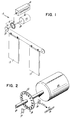
- An apparatus, generally indicated at 10 in Figure 1 and embodying the principles of the present invention, for controlling an elevator door 12 includes means 14 for moving an elevator door 12 , means 16 for generating pulses when the elevator door 12 is in motion, and means 18 for controlling the elevator door moving means 14 in accordance with the pulses generated.
- the controlling means 18 includes means 20 for counting the generated pulses when the elevator door 12 is in motion and means 22 for comparing the counted pulses to a stored elevator door profile map 24 relating the position of the elevator door 12 with the number of pulses counted.
- the means 14 for moving the elevator door includes a motor 26 having a drive shaft 28 .
- the drive shaft 28 is connected to the elevator door 12 by means 30 for converting the rotational motion of the drive shaft 28 to the linear motion of the elevator door 12 .
- the drive shaft 28 could be connected to the elevator door 12 by a pulley driving a set of linkage arms.
- the drive shaft 28 may be connected to a pulley that drives a belt drive connected to the elevator door 12 .
- the relationship between the rotation of the drive shaft 28 and the linear distance travelled by the elevator door 12 is known. This transmission ratio is thus a known factor regardless of whether the elevator door 12 is a double door system or a single door system.
- Such rotational motion to linear motion conversion systems are quite well known in the art and further detailed discussion is not believed necessary herein for a full understanding of the present invention.
- the motor 26 is a three phase AC motor that, as more fully discussed below, receives control signals from the control means 18 .
- a three phase AC motor is that the electromechanical relationships thereof are well known.
- the frequency corresponds to the speed of rotation of the drive shaft 28
- the voltage corresponds to the torque of the motor 26
- the phase is related to the direction of rotation of the drive shaft 28 .
- by controlling the frequency, voltage and phase of the motor 26 the speed, torque and direction thereof can be controlled.
- a three phase AC motor is preferred, other types of motors, including DC motors, can also be used in conjunction with the present invention.
- the means 16 for generating pulses when the elevator door 12 is in motion includes an encoder disk 32 rigidly mounted on the drive shaft 28 of the motor 26 .
- the means 16 also includes a light source 34 disposed on one side on the encoder disk 32 and a light receiver 36 disposed on the opposite side of the encoder disk 32 .
- the encoder disk 32 in such an embodiment, includes a plurality of regularly spaced openings 38 about the periphery thereof.
- the encoder disk 32 acts as a light chopper to provide a stream of light pulses to the light receiver 36 .
- the light receiver 36 In response to each light pulse striking the light receiver 36 , the light receiver 36 generates an electrical output signal. As shown, the electrical signals so generated are outputted to the means 18 for controlling the elevator door moving means 14 .
- the means 18 for controlling the elevator door moving means 14 in this embodiment the three phase AC motor 26 , includes the means 20 for counting pulses and the means 22 for comparing the counted pulses, as a percentage of the total number of pulses for full door travel in one direction, to the profile map 24 .
- the means 18 includes a microprocessor 40 and an associated memory 42 wherein the preselected profile map 24 is stored. Further, the memory 42 is also provided with the relevant motor characteristics, such as the voltage/torque ratio, the frequency/speed ratio and the phase/direction information.
- the controller 18 further includes voltage, frequency and phase output signals 43 for controlling the torque, speed and direction, respectively, of the motor 26 .
- the controller means 18 is initialized so that the profile map 24 represented in the memory 42 is executed each time the elevator door 12 is opened or closed.
- a typical profile map 24 is shown in Figure 4.
- the distance travelled by the door is shown on a scale of percentage movement with the full travel of the door 12 being 100%.
- the motor switching points i.e., from high torque to high speed or high speed to high torque, are located at predetermined points along the door path.
- the distance travelled by the door 12 is plotted along the horizontal axis with the vertical axis representing the speed of the door 12 during the travel.
- the profile shown in Figure 4 will be taken to represent a fully opened door at the extreme right of the profile.
- the door begins to move at a very slow speed, i.e., a creeping speed.
- the door 12 continues to move at this speed for between about 0% to about 10% of the total distance to be traveled.
- the speed is ramped up to a closing speed, typically the ramping occurs over about the next 10% of the total distance to be travelled by the door 12 .
- the closing speed is reached the door 12 continues to move at that speed for about the next 50% of the total distance to be travelled by the door 12 .
- the speed of the motor 26 is reduced to a preselected closing speed over the next 20% of the total distance travelled. Thereafter, the door 12 continues at that closing speed until a mechanical stop is reached.
- the speed versus distance profile can, in essence, be reversed in order to open the elevator door 12 .
- the speed change points as well as the actual speeds can be varied to suit any door or generate any profile desired.
- the profile can be adjusted for either a single door or a double door, the profile can be adjusted to accommodate any desired motor as well as to accommodate various gear systems.
- the present apparatus 10 for controlling the elevator door 12 is applicable and adaptable for use with any elevator door system.
- the motor control points along the profile are flagged or indicated to the microprocessor 40 by the means 22 for comparing the number of pulses counted with the stored profile map so that the position of the door is always "known" to the microprocessor 40 .
- the means 22 is represented as a "hardware" block in Figure 3, it is to be understood that it can be a software routine that continuously monitors, or counts the pulse counts generated by the light receiver 36 .
- the means 18 for controlling the motor 26 can thus control the movement of the elevator door 12 in accordance with the number of pulses counted.
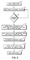
- This initialization is accomplished, in the preferred embodiment, in accordance with the exemplary flow diagram shown in Figure 5. It will be understood that the initialization is controlled by a software program stored in the memory 42 of the microprocessor 40 .
- the elevator door 12 is moved, at block 46 , from one extreme position to the other extreme position, i.e., the elevator door 12 is either opened or closed.
- the field personel is then prompted by the microprocessor 40 to input, at block 48 , the direction of door movement.
- the input causes the direction, i.e., the phase of the motor 26 , to be electronically changed and the movement of the elevator door 12 is repeated.
- the phase/direction information is stored in the memory 42 . Thereafter, the controller 18 , based upon the phase/direction information stored, will always be able to control the direction of door movement. This is particularly critical during reversals so that when an object is sensed, for example by a sudden decrease in pulses generated by the light receiver 36 or by a conventional mechanical sensor, in the path of the elevator door 12 , the direction of door movement can be reversed quickly by the microprocessor 40 .
- the field personel is prompted to initiate a second learning run.
- the elevator door 12 is then driven to a mechanical stop, i.e., either fully opened or fully closed, indicated at block 50 .
- the pulse counter 20 is set to zero by the microprocessor 40 .
- the elevator door 12 is then driven to the opposite mechanical stop, i.e., fully closed or fully opened, respectively, at a predetermined constant speed. During this movement the number of pulses are counted and the time measured for completion of the distance travelled. As a result, as shown at block 54 , a reference speed is determined in relation to the number of pulses counted. Further, as shown at block 56 , the total number of pulses occurring during the travel between mechanical stops are also counted and stored. The installation is then completed, as indicated at block 58 .
- the total number of pulses counted is then set to represent 100% of the distance travelled by the door 12 during one direction.
- the 100% normalization is then used to control the motor 26 in accordance with the profile map 24 .
- the profile for the elevator door 12 includes a plurality of control points along the path of the door 12 whereat motor commands are outputted by the controller 18 to conform the action of the motor 26 to that of the profile.
- the microprocessor 40 in conjunction with the means 22 for comparing the counted pulses with the can include a means 60 for monitoring the apparatus 10 to indicate that the apparatus 10 is misaligned. This is preferably accomplished by making a comparison between the total number of pulses counted at the end of each full run of the door 12 to the total number of pulses counted during the initialization. If the two totals are the same, then the door movement with respect to the rotation of the drive shaft 28 has not changed. However, if the totals are different, then there has been a change in the relationship between the drive shaft 28 and the door movement, for example, a mechanical gear or linkage may be worn or slippage of the belt drive may have occurred. When such a difference is detected by the monitoring means 60 , a signal, for example, either electronic, audio, visual, or a combination thereof can be generated.
Landscapes
- Engineering & Computer Science (AREA)
- Automation & Control Theory (AREA)
- Human Computer Interaction (AREA)
- Manufacturing & Machinery (AREA)
- Physics & Mathematics (AREA)
- General Physics & Mathematics (AREA)
- Elevator Door Apparatuses (AREA)
- Power-Operated Mechanisms For Wings (AREA)
Applications Claiming Priority (2)
| Application Number | Priority Date | Filing Date | Title |
|---|---|---|---|
| US227435 | 1994-04-14 | ||
| US08/227,435 US5587565A (en) | 1994-04-14 | 1994-04-14 | Method for controlling elevator doors |
Publications (3)
| Publication Number | Publication Date |
|---|---|
| EP0677475A2 true EP0677475A2 (fr) | 1995-10-18 |
| EP0677475A3 EP0677475A3 (fr) | 1996-07-17 |
| EP0677475B1 EP0677475B1 (fr) | 2000-06-21 |
Family
ID=22853097
Family Applications (1)
| Application Number | Title | Priority Date | Filing Date |
|---|---|---|---|
| EP95301951A Expired - Lifetime EP0677475B1 (fr) | 1994-04-14 | 1995-03-23 | Système et méthode pour contrôler des portes d'ascenseur |
Country Status (4)
| Country | Link |
|---|---|
| US (1) | US5587565A (fr) |
| EP (1) | EP0677475B1 (fr) |
| DE (1) | DE69517546T2 (fr) |
| RU (1) | RU2146644C1 (fr) |
Cited By (12)
| Publication number | Priority date | Publication date | Assignee | Title |
|---|---|---|---|---|
| EP0841292A1 (fr) * | 1996-11-07 | 1998-05-13 | Otis Elevator Company | Système de positionnement et de synchronisation des portes de cabine de d'ascenseur |
| EP0923012A2 (fr) | 1997-12-11 | 1999-06-16 | Tecnolama, S.A. | Procédure et dispositif d'ouverture et de fermeture de portes d'ascenseurs |
| EP0809163A3 (fr) * | 1996-05-17 | 1999-07-28 | Nabco Limited | Système de porte automatique avec fonction d'autodiagnostic |
| FR2800787A1 (fr) * | 1999-11-09 | 2001-05-11 | Jean Marie Lanfranchi | Dispositif de commande de l'ouverture/fermeture d'un portail motorise, et systeme de portail motorise l'incorporant |
| FR2810656A1 (fr) * | 2000-06-27 | 2001-12-28 | Otis Elevator Co | Ensemble actionneur de portes a galets entraines par moteur |
| ES2187385A1 (es) * | 2001-11-28 | 2003-06-01 | Gonzalez Jose Joaquin Iranzo | Dispositivo para el accionamiento y control de puertas en general |
| EP1046775A3 (fr) * | 1999-04-23 | 2003-07-09 | tormatic GmbH | Unité d'entraínement pour une porte |
| EP1170646A3 (fr) * | 2000-06-06 | 2003-10-29 | Meritor Light Vehicle Technology, LLC | Méthode et appareil de commande d'un système de vitre électrique utilisant le couple moteur en paramétre |
| WO2003014845A3 (fr) * | 2001-08-06 | 2003-10-30 | Emerson Electric Co | Systeme de commande d'appareil avec indicateurs de fonctionnement a del |
| WO2007040846A1 (fr) * | 2005-09-30 | 2007-04-12 | Wayne-Dalton Corp. | Operateur de barriere a vitesse constante adaptative |
| CN102741148A (zh) * | 2009-09-18 | 2012-10-17 | 因温特奥股份公司 | 电梯轿厢 |
| EP3271279B1 (fr) | 2015-03-18 | 2019-05-01 | Otis Elevator Company | Système et procédé pour commander une cabine d'ascenseur |
Families Citing this family (20)
| Publication number | Priority date | Publication date | Assignee | Title |
|---|---|---|---|---|
| JP3883611B2 (ja) * | 1996-07-03 | 2007-02-21 | 三菱電機株式会社 | エレベータドア制御装置 |
| US5929580A (en) * | 1997-08-05 | 1999-07-27 | Wayne-Dalton Corp. | System and related methods for detecting an obstruction in the path of a garage door controlled by an open-loop operator |
| WO2000072436A1 (fr) * | 1999-05-21 | 2000-11-30 | Automatic Technology Australia Pty Ltd | Systeme de commande et procede pour porte ou portail automatique |
| US6326751B1 (en) | 1999-08-25 | 2001-12-04 | Wayne-Dalton Corp. | System and related methods for detecting and measuring the operational parameters of a garage door utilizing a lift cable system |
| EP1389256A2 (fr) * | 2001-04-25 | 2004-02-18 | The Chamberlain Group, Inc. | Procede et dispositif facilitant la commande d'un manipulateur de barriere mobile |
| US7040457B1 (en) | 2001-11-08 | 2006-05-09 | Bene Wayne J | Motor speed controller system for freight elevator doors |
| US7156210B2 (en) * | 2003-02-24 | 2007-01-02 | The Peelle Company Ltd. | Freight elevator landing door control |
| US20050099150A1 (en) * | 2003-11-10 | 2005-05-12 | Scott Nicholson | Door control apparatus and method |
| US20050150727A1 (en) * | 2004-01-12 | 2005-07-14 | Company Steven L. | Door operator for elevators with selectable opening lengths, speed and side |
| WO2007028850A1 (fr) * | 2005-09-05 | 2007-03-15 | Kone Corporation | Systeme d'ascenseur |
| FI117701B (fi) * | 2005-11-24 | 2007-01-31 | Kone Corp | Laitteisto ja menetelmä hissin oven ohjaamiseksi |
| US8375635B2 (en) | 2009-08-26 | 2013-02-19 | Richard Hellinga | Apparatus for opening and closing overhead sectional doors |
| CN104918874B (zh) * | 2013-01-08 | 2018-09-14 | 奥的斯电梯公司 | 包括一个或多个标记的电梯门摩擦皮带传动器 |
| CN104876102B (zh) * | 2015-04-28 | 2016-06-08 | 深圳市海浦蒙特科技有限公司 | 基于位置校验的门机控制方法和系统 |
| DE102015208206A1 (de) | 2015-05-04 | 2016-11-10 | Franz Xaver Meiller Fahrzeug- Und Maschinenfabrik - Gmbh & Co Kg | Schiebetür, insbesondere Aufzugschiebetür |
| EP3315450B1 (fr) * | 2016-10-31 | 2019-10-30 | Otis Elevator Company | Test automatique de dispositif de dissuasion |
| EP3434634B2 (fr) | 2017-07-25 | 2024-07-03 | Otis Elevator Company | Dispositif de sécurité d'ascenseur |
| JP2019116360A (ja) * | 2017-12-27 | 2019-07-18 | 株式会社日立ビルシステム | エレベーターのドア制御装置、ドアの開閉制御方法及びエレベーター |
| EP3569553A1 (fr) * | 2018-05-18 | 2019-11-20 | Otis Elevator Company | Système d'ascenseur et procédé de commande d'une porte dans un système d'ascenseur |
| CN121827652A (zh) * | 2018-08-09 | 2026-04-10 | 纳博特斯克有限公司 | 自动门保养辅助系统、自动门装置、自动门保养辅助方法以及存储介质 |
Family Cites Families (12)
| Publication number | Priority date | Publication date | Assignee | Title |
|---|---|---|---|---|
| US4305481A (en) * | 1979-12-27 | 1981-12-15 | Otis Elevator Company | Elevator door motion modification |
| US4832158A (en) * | 1987-01-20 | 1989-05-23 | Delaware Capital Formation, Inc. | Elevator system having microprocessor-based door operator |
| JPH0725501B2 (ja) * | 1988-04-15 | 1995-03-22 | 三菱電機株式会社 | エレベータの制御装置 |
| JP2504257B2 (ja) * | 1990-02-16 | 1996-06-05 | 三菱電機株式会社 | エレベ―タ―のドア制御装置 |
| JPH0459586A (ja) * | 1990-06-29 | 1992-02-26 | Mitsubishi Electric Corp | エレベータのドア制御装置 |
| US5157228A (en) * | 1990-09-28 | 1992-10-20 | Otis Elevator Company | Adjusting technique for a digital elevator drive system |
| DE9116228U1 (de) * | 1991-02-20 | 1992-06-04 | Siemens AG, 8000 München | Einrichtung zur Betriebssteuerung einer automatischen Tür |
| FR2673616B1 (fr) * | 1991-03-07 | 1993-07-16 | Otis Elevator Co | Dispositif de controle de moteur, notamment pour l'entrainement de portes d'ascenseur. |
| DE59205488D1 (de) * | 1991-12-24 | 1996-04-04 | Inventio Ag | Verfahren und Vorrichtung zur Bestimmung der dynamischen Masse un der mittleren Reibkraft einer Aufzugstüre |
| US5378861A (en) * | 1993-02-16 | 1995-01-03 | Otis Elevator Company | Automatic setting of the parameters of a profile generator for a high performance elevator door system |
| US5389864A (en) * | 1993-03-29 | 1995-02-14 | Lake Center Industries, Inc. | Actuator with motor and feedback driven by a common power supply |
| DE9307326U1 (de) * | 1993-05-14 | 1993-07-29 | Siemens AG, 80333 München | Türsteuereinheit |
-
1994
- 1994-04-14 US US08/227,435 patent/US5587565A/en not_active Expired - Lifetime
-
1995
- 1995-03-23 DE DE69517546T patent/DE69517546T2/de not_active Expired - Lifetime
- 1995-03-23 EP EP95301951A patent/EP0677475B1/fr not_active Expired - Lifetime
- 1995-04-11 RU RU95105424A patent/RU2146644C1/ru active
Cited By (19)
| Publication number | Priority date | Publication date | Assignee | Title |
|---|---|---|---|---|
| EP0809163A3 (fr) * | 1996-05-17 | 1999-07-28 | Nabco Limited | Système de porte automatique avec fonction d'autodiagnostic |
| EP0841292A1 (fr) * | 1996-11-07 | 1998-05-13 | Otis Elevator Company | Système de positionnement et de synchronisation des portes de cabine de d'ascenseur |
| EP0923012A2 (fr) | 1997-12-11 | 1999-06-16 | Tecnolama, S.A. | Procédure et dispositif d'ouverture et de fermeture de portes d'ascenseurs |
| EP0923012A3 (fr) * | 1997-12-11 | 1999-07-21 | Tecnolama, S.A. | Procédure et dispositif d'ouverture et de fermeture de portes d'ascenseurs |
| ES2134165A1 (es) * | 1997-12-11 | 1999-09-16 | Tecnolama S A | Procedimiento y dispositivo para el cierre y la apertura de puertas de aparatos elevadores. |
| EP1046775A3 (fr) * | 1999-04-23 | 2003-07-09 | tormatic GmbH | Unité d'entraínement pour une porte |
| FR2800787A1 (fr) * | 1999-11-09 | 2001-05-11 | Jean Marie Lanfranchi | Dispositif de commande de l'ouverture/fermeture d'un portail motorise, et systeme de portail motorise l'incorporant |
| EP1170646A3 (fr) * | 2000-06-06 | 2003-10-29 | Meritor Light Vehicle Technology, LLC | Méthode et appareil de commande d'un système de vitre électrique utilisant le couple moteur en paramétre |
| FR2810656A1 (fr) * | 2000-06-27 | 2001-12-28 | Otis Elevator Co | Ensemble actionneur de portes a galets entraines par moteur |
| WO2003014845A3 (fr) * | 2001-08-06 | 2003-10-30 | Emerson Electric Co | Systeme de commande d'appareil avec indicateurs de fonctionnement a del |
| US6862482B2 (en) | 2001-08-06 | 2005-03-01 | Emerson Electric Co. | Appliance control system with LED operation indicators |
| WO2003046322A1 (fr) * | 2001-11-28 | 2003-06-05 | Iranzo Gonzalez Jose Joaquin | Dispositif d'actionnement et de commande de portes en général |
| ES2187385B1 (es) * | 2001-11-28 | 2004-07-16 | Jose Joaquin Iranzo Gonzalez | Dispositivo para el accionamiento y control de puertas en general. |
| ES2187385A1 (es) * | 2001-11-28 | 2003-06-01 | Gonzalez Jose Joaquin Iranzo | Dispositivo para el accionamiento y control de puertas en general |
| WO2007040846A1 (fr) * | 2005-09-30 | 2007-04-12 | Wayne-Dalton Corp. | Operateur de barriere a vitesse constante adaptative |
| US7521881B2 (en) | 2005-09-30 | 2009-04-21 | Wayne-Dalton Corp. | Constant speed barrier operator |
| CN102741148A (zh) * | 2009-09-18 | 2012-10-17 | 因温特奥股份公司 | 电梯轿厢 |
| CN102741148B (zh) * | 2009-09-18 | 2015-06-17 | 因温特奥股份公司 | 电梯轿厢 |
| EP3271279B1 (fr) | 2015-03-18 | 2019-05-01 | Otis Elevator Company | Système et procédé pour commander une cabine d'ascenseur |
Also Published As
| Publication number | Publication date |
|---|---|
| DE69517546D1 (de) | 2000-07-27 |
| RU95105424A (ru) | 1997-03-10 |
| RU2146644C1 (ru) | 2000-03-20 |
| EP0677475B1 (fr) | 2000-06-21 |
| DE69517546T2 (de) | 2001-03-08 |
| EP0677475A3 (fr) | 1996-07-17 |
| US5587565A (en) | 1996-12-24 |
Similar Documents
| Publication | Publication Date | Title |
|---|---|---|
| EP0677475B1 (fr) | Système et méthode pour contrôler des portes d'ascenseur | |
| KR910001853B1 (ko) | 자동문을 위한 문 개폐 모우터의 토오크 제어 방법 | |
| FI93940B (fi) | Menetelmä ja laite automaattisissa ovissa sattuvien kiinnijuuttumisien vähentämiseksi | |
| US7034488B2 (en) | Automatic gate operator | |
| US8098030B2 (en) | Drive unit for a door or gate, particularly for a garage door, and method for operating such drive unit | |
| US4980618A (en) | Microcontroller based automatic door obstruction detector | |
| CA2452919A1 (fr) | Methode, systeme et appareil ameliores d'ouverture de portes | |
| US5764008A (en) | Drive device for closing parts in motor vehicles | |
| JPH0229151B2 (fr) | ||
| CA2521704C (fr) | Entree ou reglage de positions de reference pour dispositif de commande de porte | |
| US6343437B1 (en) | Door drive with integrated diagnosis of the door operation | |
| EP1982035A1 (fr) | Systèmes et procédés de surveillance de cloisons mobiles | |
| US5063337A (en) | Electric motor regulation to obtain desired speed curve | |
| JPH0228669B2 (fr) | ||
| CN107406221B (zh) | 用于控制电梯轿厢的系统和方法 | |
| US6646399B2 (en) | Controller for shutting apparatus | |
| EP0162280A1 (fr) | Mécanisme de frein pour une porte automatique | |
| CA2772281C (fr) | Cabine d'ascenseur | |
| JP2531024B2 (ja) | エレベ―タ―のドア制御装置 | |
| CN1094651A (zh) | 随动控制舞台拉幕系统 | |
| EP0923012A2 (fr) | Procédure et dispositif d'ouverture et de fermeture de portes d'ascenseurs | |
| US20050099150A1 (en) | Door control apparatus and method | |
| EP2003277A2 (fr) | Appareil de contrôle de mouvement des portes, barrières et similaires | |
| JPH07208017A (ja) | 被駆動物の制御装置 | |
| HK1091187B (en) | Inputting or adjusting reference positions in a door controller |
Legal Events
| Date | Code | Title | Description |
|---|---|---|---|
| PUAI | Public reference made under article 153(3) epc to a published international application that has entered the european phase |
Free format text: ORIGINAL CODE: 0009012 |
|
| AK | Designated contracting states |
Kind code of ref document: A2 Designated state(s): DE FR GB IT |
|
| PUAL | Search report despatched |
Free format text: ORIGINAL CODE: 0009013 |
|
| AK | Designated contracting states |
Kind code of ref document: A3 Designated state(s): DE FR GB IT |
|
| 17P | Request for examination filed |
Effective date: 19961008 |
|
| 17Q | First examination report despatched |
Effective date: 19981028 |
|
| GRAG | Despatch of communication of intention to grant |
Free format text: ORIGINAL CODE: EPIDOS AGRA |
|
| GRAG | Despatch of communication of intention to grant |
Free format text: ORIGINAL CODE: EPIDOS AGRA |
|
| GRAH | Despatch of communication of intention to grant a patent |
Free format text: ORIGINAL CODE: EPIDOS IGRA |
|
| GRAH | Despatch of communication of intention to grant a patent |
Free format text: ORIGINAL CODE: EPIDOS IGRA |
|
| ITF | It: translation for a ep patent filed | ||
| GRAA | (expected) grant |
Free format text: ORIGINAL CODE: 0009210 |
|
| AK | Designated contracting states |
Kind code of ref document: B1 Designated state(s): DE FR GB IT |
|
| REF | Corresponds to: |
Ref document number: 69517546 Country of ref document: DE Date of ref document: 20000727 |
|
| ET | Fr: translation filed | ||
| PGFP | Annual fee paid to national office [announced via postgrant information from national office to epo] |
Ref country code: GB Payment date: 20010219 Year of fee payment: 7 |
|
| PLBE | No opposition filed within time limit |
Free format text: ORIGINAL CODE: 0009261 |
|
| STAA | Information on the status of an ep patent application or granted ep patent |
Free format text: STATUS: NO OPPOSITION FILED WITHIN TIME LIMIT |
|
| 26N | No opposition filed | ||
| REG | Reference to a national code |
Ref country code: GB Ref legal event code: IF02 |
|
| PG25 | Lapsed in a contracting state [announced via postgrant information from national office to epo] |
Ref country code: GB Free format text: LAPSE BECAUSE OF NON-PAYMENT OF DUE FEES Effective date: 20020323 |
|
| GBPC | Gb: european patent ceased through non-payment of renewal fee |
Effective date: 20020323 |
|
| PG25 | Lapsed in a contracting state [announced via postgrant information from national office to epo] |
Ref country code: IT Free format text: LAPSE BECAUSE OF NON-PAYMENT OF DUE FEES Effective date: 20050323 |
|
| PGFP | Annual fee paid to national office [announced via postgrant information from national office to epo] |
Ref country code: FR Payment date: 20140311 Year of fee payment: 20 |
|
| PGFP | Annual fee paid to national office [announced via postgrant information from national office to epo] |
Ref country code: DE Payment date: 20140417 Year of fee payment: 20 |
|
| REG | Reference to a national code |
Ref country code: DE Ref legal event code: R071 Ref document number: 69517546 Country of ref document: DE |