EP0677615A1 - Configuration variable de glissière de sécurité routière à moyens de dissipation de l'énergie - Google Patents
Configuration variable de glissière de sécurité routière à moyens de dissipation de l'énergie Download PDFInfo
- Publication number
- EP0677615A1 EP0677615A1 EP94830497A EP94830497A EP0677615A1 EP 0677615 A1 EP0677615 A1 EP 0677615A1 EP 94830497 A EP94830497 A EP 94830497A EP 94830497 A EP94830497 A EP 94830497A EP 0677615 A1 EP0677615 A1 EP 0677615A1
- Authority
- EP
- European Patent Office
- Prior art keywords
- upright
- barrier
- base plate
- pin
- slot
- Prior art date
- Legal status (The legal status is an assumption and is not a legal conclusion. Google has not performed a legal analysis and makes no representation as to the accuracy of the status listed.)
- Granted
Links
- 230000004888 barrier function Effects 0.000 title claims abstract description 71
- 230000008878 coupling Effects 0.000 claims description 3
- 238000010168 coupling process Methods 0.000 claims description 3
- 238000005859 coupling reaction Methods 0.000 claims description 3
- 238000006073 displacement reaction Methods 0.000 claims description 2
- 238000006243 chemical reaction Methods 0.000 description 3
- 238000010276 construction Methods 0.000 description 2
- 238000003466 welding Methods 0.000 description 2
- 230000009471 action Effects 0.000 description 1
- 238000004873 anchoring Methods 0.000 description 1
- 230000000694 effects Effects 0.000 description 1
- 239000000463 material Substances 0.000 description 1
- 239000002184 metal Substances 0.000 description 1
- 230000004048 modification Effects 0.000 description 1
- 238000012986 modification Methods 0.000 description 1
- 230000010355 oscillation Effects 0.000 description 1
Images



Classifications
-
- E—FIXED CONSTRUCTIONS
- E01—CONSTRUCTION OF ROADS, RAILWAYS, OR BRIDGES
- E01F—ADDITIONAL WORK, SUCH AS EQUIPPING ROADS OR THE CONSTRUCTION OF PLATFORMS, HELICOPTER LANDING STAGES, SIGNS, SNOW FENCES, OR THE LIKE
- E01F15/00—Safety arrangements for slowing, redirecting or stopping errant vehicles, e.g. guard posts or bollards; Arrangements for reducing damage to roadside structures due to vehicular impact
- E01F15/02—Continuous barriers extending along roads or between traffic lanes
- E01F15/04—Continuous barriers extending along roads or between traffic lanes essentially made of longitudinal beams or rigid strips supported above ground at spaced points
- E01F15/0407—Metal rails
- E01F15/0415—Metal rails with pivoting members
Definitions
- the present invention relates to a variable configuration or geometry road barrier, including energy dissipating means.
- guard-rails which usually comprise metal section members, affixed to upright associated with the ground near the road edges.
- the aim of the present invention is to overcome the above mentioned problem, by providing a variable configuration road barrier, which is adapted to provide a high dissipation of the impact energy, so as to prevent the vehicle from being subjected to high elastic reaction forces.
- a main object of the present invention is to provide such a road barrier which can be assembled in a very simple and quick manner, which comprises a very reduced number of component parts, and which, moreover, is very reliable and safe in operation.
- a variable configuration road barrier including energy dissipating means
- said barrier comprises a base plate, which can be affixed to the ground, said base plate supporting an upright pivoted to said base plate and provided, on the side thereof facing the ground surface, with means for coupling a barrier element, there being moreover provided a strut, arranged on the upright side opposite to said barrier and pivoted, at the top end portion thereof, to said upright and, at the bottom end portion thereof, to said base plate, said upright being moreover provided, between the region thereof pivoted to said strut and the region thereof pivoted to said base plate, with means for varying the useful length of said upright, for allowing said upright to partially rotate with respect to said base plate, toward the strut; near said upright length varying means there being furthermore provided energy dissipating means which operate against the length variation of said upright.
- variable configuration or geometry road barrier including energy dissipating means, which are illustrated, by way of an indicative, but not limitative, example, in the figures of the accompanying drawings, where:
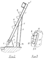
- the first embodiment of the road barrier according to the present invention which has been shown in Figures 1 to 3 and has been generally indicated at the reference number 1, comprises an upright 2, vertically extending and being pivoted, near the bottom end portion thereof, to a base plate 3 which is affixed to the ground.
- the upright 2 is provided, on the side thereof provided for facing the road surface, with means for connecting at least a barrier element 4.
- the road barrier assembly further comprises a strut 5, which is arranged on the side of the upright 2 opposite to the road surface and being pivoted, at the top end portion thereof, to a middle region of the upright 2.
- said strut 5 is pivoted, at the bottom end portion thereof, to a base plate 3a which can be made as a single piece with the base plate 3 or, as is shown, it can consist of a separated element affixed, as the base plate 3, to the ground near the edges of the road.
- the road barrier assembly owing to the pivoting of the upright 2 to the strut 1 and the pivoting of the latter to the base plates 3 and 3a, will have the configuration of a three-hinge arch.
- the barrier assembly comprises means for varying, upon an impact, the useful length of the upright 2 and, more specifically, these upright length changing means comprise a pivot pin 6 which pivotably connects the upright 2 to the base plate 3.
- the pin 6 passes through a slot 7 which is provided through the base plate 3 and extends along a direction with a vertical component.
- energy dissipating means operating against this variation of the useful length of the upright.
- said energy dissipating means substantially comprise elements adapted to provide a narrowing, to a size less than the diameter of the pivot pin 6, of the slot 7 at the region not occupied by the pin 6, as the upright 2 is in a rest condition, that is as it vertically extends without impacts exerted thereon.
- the narrowing means comprise a dissipating plate 8 which is affixed, for example by welding, to the base plate 3, at the slot 7.
- the end portion of the dissipating plate 8 facing the pin 6, as the upright 2 is under not stressed conditions, is provided with a cut-out or beveled portion 9, adapted to prevent the pin from locking as a motor vehicle impacts gainst the barrier.
- the dissipating plate 8 can also be advantageously provided with a first portion 10 and a second portion 11 having mutually different thicknesses.
- the first portion 10 has a thickness less than the thickness of the second portion 11, so as to provide an increasing energy dissipating effect, as the impact force increases.
- the subject road barrier in its second embodiment, shown in Figures 4 to 6, and generally indicated at the reference number 21, comprises an upright 22 which vertically extends and is pivoted, near its bottom, to a base plate 23, affixed to the ground.
- the upright 22, likewise the upright 2 of the first embodiment, is provided, on the side thereof provided for facing the road surface, with means for coupling at least a barrier 24, and is pivoted, on the side thereof provided for facing the opposite portion, with respect to the road surface, to a strut 25.
- the strut 25 is pivoted, at the top end portion thereof, to a middle region of the upright 22 and is pivoted, at the bottom end portion thereof, to a base plate 23a which can be made as a single piece, or as a piece separated from the base plate 23.
- the means for varying the useful length of the upright 22 comprise two assembled pieces of the same upright 22.
- the upright 22 comprises a bottom portion 22a, pivoted to the base plate 23, and a top portion 22b, slidably associated, along a direction parallel to its longitudinal extension, with the bottom portion 22a.
- the top portion 22b is connected to the bottom portion 22a by a pin 26, which is in turn coupled to the top portion 22b and passes through a slot 27, formed through the bottom portion 22a and extending along a direction with a vertical component.
- the energy dissipating means comprise, in a like manner to that disclosed for the first embodiment, means for narrowing or throttling the slot 27, which, any stresses on the upright 22 being absent, will limit the size of the slot 27 portion not engaged by the pin 26, to a size less than the diameter of said pin 26.
- the above mentioned limiting or narrowing means also in this second embodiment, comprise a dissipating plate 28, which is coupled to the bottom portion 22b of the upright 22, for example by welding, and being preferably constituted by two portions, indicated respectively at 30 and 31, having different thicknesses.
- the end of the dissipating plate 28 facing the pin 26 is provided with a lead-in beveled portion.
- variable configuration or geometry barrier including energy dissipating means, according to the present invention.
- the upright 2, respectively 22 Upon an impact, the upright 2, respectively 22, will be caused to partially turn toward the outside of the road surface, and such an oscillation will be allowed exclusively by a variation of the useful length of the upright 2 respectively 22.
- said variation of the useful length of the upright 2 or 22, can be performed, in the barrier, according to the present invention, only by causing the pin 6 or 26 to slide in the slot 7 or 27.
- the construction of the dissipating plate 8, which comprises several sequential portions of mutually different thicknesses, will allow the barrier to provide a different performance, depending on the impact forces applied to the upright 2 or 22.
- variable configuration or geometry safety barrier will fit its configuration or geometrical pattern depending on the impact energy, and will respond gradually by vertical and horizontal displacements which are controlled by the energy dissipating means associated to the barrier, which, after a dissipating operation, will operate as a safety limit means.
- the subject barrier will provide a preset pattern of the forces acting on the bottom fixing or anchoring means of the barrier itself.
- variable configuration or geometry road barrier including energy dissipating means, according to the present invention, fully achieves the intended aim and objects.
- variable configuration road barrier which is specifically designed for preventing motor vehicles from being resiliently rejected from the barrier upon accidental impacts.
- the used material as well as the contingent size and shapes, can be any, depending on requirements.
- the subject barrier is adapted to absorb the greatest portion of the impact kinetic energy, as an impact occurs against said barrier, and this by providing such a resilient resistance effective to slow down the motion of the vehicle in a gradual manner.
- the above disclosed sliding means upon achieving their limit position, will allow the subject barrier to provide a holding action on the motor vehicle preventing the latter from being ejected from the road.
Landscapes
- Engineering & Computer Science (AREA)
- Architecture (AREA)
- Civil Engineering (AREA)
- Structural Engineering (AREA)
- Refuge Islands, Traffic Blockers, Or Guard Fence (AREA)
- Road Signs Or Road Markings (AREA)
- Road Paving Structures (AREA)
Applications Claiming Priority (2)
| Application Number | Priority Date | Filing Date | Title |
|---|---|---|---|
| ITMI940715 | 1994-04-14 | ||
| ITMI940715A IT1270033B (it) | 1994-04-14 | 1994-04-14 | Barriera stradale a geometria variabile, con mezzi di dissipazione di energia |
Publications (2)
| Publication Number | Publication Date |
|---|---|
| EP0677615A1 true EP0677615A1 (fr) | 1995-10-18 |
| EP0677615B1 EP0677615B1 (fr) | 2001-04-18 |
Family
ID=11368597
Family Applications (1)
| Application Number | Title | Priority Date | Filing Date |
|---|---|---|---|
| EP94830497A Expired - Lifetime EP0677615B1 (fr) | 1994-04-14 | 1994-10-25 | Configuration variable de glissière de sécurité routière à moyens de dissipation de l'énergie |
Country Status (5)
| Country | Link |
|---|---|
| EP (1) | EP0677615B1 (fr) |
| AT (1) | ATE200698T1 (fr) |
| DE (1) | DE69427118T2 (fr) |
| ES (1) | ES2157969T3 (fr) |
| IT (1) | IT1270033B (fr) |
Cited By (11)
| Publication number | Priority date | Publication date | Assignee | Title |
|---|---|---|---|---|
| US6551012B1 (en) * | 1998-12-10 | 2003-04-22 | Nederladnse Organisatie Voor Toegepast-Natuurwetenschappelijk On-Derzoek Tno | Guard rail construction |
| EP1520934A1 (fr) * | 2003-09-30 | 2005-04-06 | TOGE-Dübel A. Gerhard KG | poteau pour barrière de sécurité |
| DE102004034999A1 (de) * | 2004-03-10 | 2005-10-13 | TOGE-Dübel A. Gerhard KG | Leitplanken-Pfosten |
| FR2928941A1 (fr) * | 2008-03-20 | 2009-09-25 | Maussion Jacques De | Poteau de glissiere de securite pour des voies de circulation de vehicules, telles que des routes, des autoroutes ou analogues |
| KR101036416B1 (ko) * | 2010-07-21 | 2011-05-24 | (주) 에스에스 | 가드레일의 지지구조 |
| EP2439339A1 (fr) | 2010-10-06 | 2012-04-11 | Lodzka Jednostka Badawcza EPAR | Barrière routière à géométrie variable et son procédé de fabrication |
| EP2628852A2 (fr) | 2011-12-15 | 2013-08-21 | DAK Acelszerkezeti Kft. | Structure pour une barrière routière de sécurité avec un poteau support et procédé pour sa installation. |
| WO2015042656A1 (fr) * | 2013-09-30 | 2015-04-02 | Safe Direction Pty Ltd | Ensemble montant |
| CN109952403A (zh) * | 2016-09-30 | 2019-06-28 | 摩林铝业有限公司 | 柔性弹性屏障 |
| IT201800003101A1 (it) * | 2018-02-27 | 2019-08-27 | Volkmann & Rossbach Gmbh & Co Kg | Barriera di sicurezza per l'arresto forzato di veicoli |
| CN112593767A (zh) * | 2020-11-26 | 2021-04-02 | 中核华辰工程管理有限公司 | 一种建筑施工用防护装置 |
Families Citing this family (1)
| Publication number | Priority date | Publication date | Assignee | Title |
|---|---|---|---|---|
| CN118273258A (zh) * | 2024-03-28 | 2024-07-02 | 华能西藏雅鲁藏布江水电开发投资有限公司 | 一种方便维修的防撞栏 |
Citations (3)
| Publication number | Priority date | Publication date | Assignee | Title |
|---|---|---|---|---|
| GB1066988A (en) * | 1964-11-11 | 1967-04-26 | Christiani & Nielsen Ltd | Improvements in or relating to highway guard rail supports |
| DE1295581B (de) * | 1966-03-23 | 1969-05-22 | Siegener Ag Geisweid Fuer Eise | Leitplanke fuer Strassen |
| AT372445B (de) * | 1980-09-15 | 1983-10-10 | Vmw Ranshofen Berndorf Ag | Leitschienenstuetze mit gummidaempfungselement |
-
1994
- 1994-04-14 IT ITMI940715A patent/IT1270033B/it active IP Right Grant
- 1994-10-25 AT AT94830497T patent/ATE200698T1/de active
- 1994-10-25 EP EP94830497A patent/EP0677615B1/fr not_active Expired - Lifetime
- 1994-10-25 ES ES94830497T patent/ES2157969T3/es not_active Expired - Lifetime
- 1994-10-25 DE DE69427118T patent/DE69427118T2/de not_active Expired - Fee Related
Patent Citations (3)
| Publication number | Priority date | Publication date | Assignee | Title |
|---|---|---|---|---|
| GB1066988A (en) * | 1964-11-11 | 1967-04-26 | Christiani & Nielsen Ltd | Improvements in or relating to highway guard rail supports |
| DE1295581B (de) * | 1966-03-23 | 1969-05-22 | Siegener Ag Geisweid Fuer Eise | Leitplanke fuer Strassen |
| AT372445B (de) * | 1980-09-15 | 1983-10-10 | Vmw Ranshofen Berndorf Ag | Leitschienenstuetze mit gummidaempfungselement |
Cited By (17)
| Publication number | Priority date | Publication date | Assignee | Title |
|---|---|---|---|---|
| US6551012B1 (en) * | 1998-12-10 | 2003-04-22 | Nederladnse Organisatie Voor Toegepast-Natuurwetenschappelijk On-Derzoek Tno | Guard rail construction |
| EP1520934A1 (fr) * | 2003-09-30 | 2005-04-06 | TOGE-Dübel A. Gerhard KG | poteau pour barrière de sécurité |
| DE102004034999A1 (de) * | 2004-03-10 | 2005-10-13 | TOGE-Dübel A. Gerhard KG | Leitplanken-Pfosten |
| FR2928941A1 (fr) * | 2008-03-20 | 2009-09-25 | Maussion Jacques De | Poteau de glissiere de securite pour des voies de circulation de vehicules, telles que des routes, des autoroutes ou analogues |
| KR101036416B1 (ko) * | 2010-07-21 | 2011-05-24 | (주) 에스에스 | 가드레일의 지지구조 |
| EP2439339A1 (fr) | 2010-10-06 | 2012-04-11 | Lodzka Jednostka Badawcza EPAR | Barrière routière à géométrie variable et son procédé de fabrication |
| EP2628852A2 (fr) | 2011-12-15 | 2013-08-21 | DAK Acelszerkezeti Kft. | Structure pour une barrière routière de sécurité avec un poteau support et procédé pour sa installation. |
| GB2535059A (en) * | 2013-09-30 | 2016-08-10 | Safe Direction Pty Ltd | Post Assembly |
| WO2015042656A1 (fr) * | 2013-09-30 | 2015-04-02 | Safe Direction Pty Ltd | Ensemble montant |
| US9758936B2 (en) | 2013-09-30 | 2017-09-12 | Safe Direction Pty Ltd | Post assembly |
| GB2535059B (en) * | 2013-09-30 | 2020-07-15 | Safe Direction Pty Ltd | Post Assembly |
| CN109952403A (zh) * | 2016-09-30 | 2019-06-28 | 摩林铝业有限公司 | 柔性弹性屏障 |
| IT201800003101A1 (it) * | 2018-02-27 | 2019-08-27 | Volkmann & Rossbach Gmbh & Co Kg | Barriera di sicurezza per l'arresto forzato di veicoli |
| WO2019166419A1 (fr) * | 2018-02-27 | 2019-09-06 | Volkmann & Rossbach Gmbh & Co. Kg | Barrière de sécurité pour l'arrêt forcé de véhicules |
| IL276657B2 (en) * | 2018-02-27 | 2025-04-01 | Volkmann & Rossbach Gmbh & Co Kg | Security barrier to force vehicles to come to a stop |
| CN112593767A (zh) * | 2020-11-26 | 2021-04-02 | 中核华辰工程管理有限公司 | 一种建筑施工用防护装置 |
| CN112593767B (zh) * | 2020-11-26 | 2021-12-10 | 中核华辰工程管理有限公司 | 一种建筑施工用防护装置 |
Also Published As
| Publication number | Publication date |
|---|---|
| DE69427118D1 (de) | 2001-05-23 |
| ITMI940715A1 (it) | 1995-10-14 |
| ATE200698T1 (de) | 2001-05-15 |
| IT1270033B (it) | 1997-04-28 |
| ITMI940715A0 (it) | 1994-04-14 |
| DE69427118T2 (de) | 2001-08-02 |
| ES2157969T3 (es) | 2001-09-01 |
| EP0677615B1 (fr) | 2001-04-18 |
Similar Documents
| Publication | Publication Date | Title |
|---|---|---|
| EP0677615A1 (fr) | Configuration variable de glissière de sécurité routière à moyens de dissipation de l'énergie | |
| US5788278A (en) | Energy-absorbing steering column for motor vehicle | |
| US5044609A (en) | Guardrail barrier | |
| KR100291566B1 (ko) | 안전바아구조물 | |
| US6543086B2 (en) | Collapsible hood hinge | |
| US4139324A (en) | Bracing system glide shoe for trench sheeting equipment | |
| JP2004536985A (ja) | 自動車両のフロントボンネット用の2本のアームを備えたヒンジ | |
| EP1710353A1 (fr) | Séparateur déformable | |
| EP0598857A1 (fr) | Dispositif servant a absorber l'energie transmise a travers la colonne de direction d'un vehicule. | |
| US2974934A (en) | Safety apparatus for highways | |
| EP0356686B1 (fr) | Barrière de sécurité à glissière | |
| US20020134020A1 (en) | Gate release mechanism with detent and plunger, and gate incorporating same | |
| KR20140010011A (ko) | 차량용 완충기 | |
| EP1842746B1 (fr) | Capot de véhicule | |
| EP0554864A1 (fr) | Barrière routière semi-rigide pour dissipation contrôlée d'énergie de choc et correction d'attitude | |
| US5417452A (en) | Steering column energy absorbing assembly | |
| DE10003744A1 (de) | Puffereinrichtung für eine LKW-Ladestation | |
| US4751801A (en) | Post for traffic signals and the like | |
| WO2000034585A1 (fr) | Structure de glissiere de securite | |
| EP1624112A1 (fr) | Élément de glissière de sécurité avec des organes déformables entre l'élément et les boulons d'ancrage | |
| KR100380363B1 (ko) | 자동차의 충격완충용 후드 로크장치 | |
| KR102790488B1 (ko) | 전복방지 가드레일 | |
| KR100380366B1 (ko) | 자동차의 충격완충용 후드 로크장치 | |
| CN223825493U (zh) | 一种吸能减震机构 | |
| KR100368407B1 (ko) | 자동차의 충격완충용 후드 로크장치 |
Legal Events
| Date | Code | Title | Description |
|---|---|---|---|
| PUAI | Public reference made under article 153(3) epc to a published international application that has entered the european phase |
Free format text: ORIGINAL CODE: 0009012 |
|
| AK | Designated contracting states |
Kind code of ref document: A1 Designated state(s): AT BE CH DE ES FR GB LI SE |
|
| 17P | Request for examination filed |
Effective date: 19960304 |
|
| 17Q | First examination report despatched |
Effective date: 19980209 |
|
| GRAG | Despatch of communication of intention to grant |
Free format text: ORIGINAL CODE: EPIDOS AGRA |
|
| GRAG | Despatch of communication of intention to grant |
Free format text: ORIGINAL CODE: EPIDOS AGRA |
|
| GRAH | Despatch of communication of intention to grant a patent |
Free format text: ORIGINAL CODE: EPIDOS IGRA |
|
| GRAH | Despatch of communication of intention to grant a patent |
Free format text: ORIGINAL CODE: EPIDOS IGRA |
|
| GRAA | (expected) grant |
Free format text: ORIGINAL CODE: 0009210 |
|
| AK | Designated contracting states |
Kind code of ref document: B1 Designated state(s): AT BE CH DE ES FR GB LI SE |
|
| PG25 | Lapsed in a contracting state [announced via postgrant information from national office to epo] |
Ref country code: LI Free format text: LAPSE BECAUSE OF FAILURE TO SUBMIT A TRANSLATION OF THE DESCRIPTION OR TO PAY THE FEE WITHIN THE PRESCRIBED TIME-LIMIT Effective date: 20010418 Ref country code: CH Free format text: LAPSE BECAUSE OF FAILURE TO SUBMIT A TRANSLATION OF THE DESCRIPTION OR TO PAY THE FEE WITHIN THE PRESCRIBED TIME-LIMIT Effective date: 20010418 Ref country code: BE Free format text: LAPSE BECAUSE OF FAILURE TO SUBMIT A TRANSLATION OF THE DESCRIPTION OR TO PAY THE FEE WITHIN THE PRESCRIBED TIME-LIMIT Effective date: 20010418 Ref country code: AT Free format text: LAPSE BECAUSE OF FAILURE TO SUBMIT A TRANSLATION OF THE DESCRIPTION OR TO PAY THE FEE WITHIN THE PRESCRIBED TIME-LIMIT Effective date: 20010418 |
|
| REF | Corresponds to: |
Ref document number: 200698 Country of ref document: AT Date of ref document: 20010515 Kind code of ref document: T |
|
| REG | Reference to a national code |
Ref country code: CH Ref legal event code: EP |
|
| REF | Corresponds to: |
Ref document number: 69427118 Country of ref document: DE Date of ref document: 20010523 |
|
| ET | Fr: translation filed | ||
| PG25 | Lapsed in a contracting state [announced via postgrant information from national office to epo] |
Ref country code: SE Free format text: LAPSE BECAUSE OF FAILURE TO SUBMIT A TRANSLATION OF THE DESCRIPTION OR TO PAY THE FEE WITHIN THE PRESCRIBED TIME-LIMIT Effective date: 20010718 |
|
| REG | Reference to a national code |
Ref country code: ES Ref legal event code: FG2A Ref document number: 2157969 Country of ref document: ES Kind code of ref document: T3 |
|
| REG | Reference to a national code |
Ref country code: CH Ref legal event code: PL |
|
| REG | Reference to a national code |
Ref country code: GB Ref legal event code: IF02 |
|
| PLBE | No opposition filed within time limit |
Free format text: ORIGINAL CODE: 0009261 |
|
| STAA | Information on the status of an ep patent application or granted ep patent |
Free format text: STATUS: NO OPPOSITION FILED WITHIN TIME LIMIT |
|
| 26N | No opposition filed | ||
| PGFP | Annual fee paid to national office [announced via postgrant information from national office to epo] |
Ref country code: FR Payment date: 20051003 Year of fee payment: 12 |
|
| PGFP | Annual fee paid to national office [announced via postgrant information from national office to epo] |
Ref country code: ES Payment date: 20051013 Year of fee payment: 12 |
|
| PGFP | Annual fee paid to national office [announced via postgrant information from national office to epo] |
Ref country code: GB Payment date: 20051019 Year of fee payment: 12 |
|
| PGFP | Annual fee paid to national office [announced via postgrant information from national office to epo] |
Ref country code: DE Payment date: 20051125 Year of fee payment: 12 |
|
| PG25 | Lapsed in a contracting state [announced via postgrant information from national office to epo] |
Ref country code: DE Free format text: LAPSE BECAUSE OF NON-PAYMENT OF DUE FEES Effective date: 20070501 |
|
| GBPC | Gb: european patent ceased through non-payment of renewal fee |
Effective date: 20061025 |
|
| REG | Reference to a national code |
Ref country code: FR Ref legal event code: ST Effective date: 20070629 |
|
| PG25 | Lapsed in a contracting state [announced via postgrant information from national office to epo] |
Ref country code: GB Free format text: LAPSE BECAUSE OF NON-PAYMENT OF DUE FEES Effective date: 20061025 |
|
| REG | Reference to a national code |
Ref country code: ES Ref legal event code: FD2A Effective date: 20061026 |
|
| PG25 | Lapsed in a contracting state [announced via postgrant information from national office to epo] |
Ref country code: FR Free format text: LAPSE BECAUSE OF NON-PAYMENT OF DUE FEES Effective date: 20061031 Ref country code: ES Free format text: LAPSE BECAUSE OF NON-PAYMENT OF DUE FEES Effective date: 20061026 |