EP0677626A1 - Dispositif de fixation de murs-videaux à ventilation arrière - Google Patents
Dispositif de fixation de murs-videaux à ventilation arrière Download PDFInfo
- Publication number
- EP0677626A1 EP0677626A1 EP95810216A EP95810216A EP0677626A1 EP 0677626 A1 EP0677626 A1 EP 0677626A1 EP 95810216 A EP95810216 A EP 95810216A EP 95810216 A EP95810216 A EP 95810216A EP 0677626 A1 EP0677626 A1 EP 0677626A1
- Authority
- EP
- European Patent Office
- Prior art keywords
- fastening
- rod
- fastening element
- head
- profile
- Prior art date
- Legal status (The legal status is an assumption and is not a legal conclusion. Google has not performed a legal analysis and makes no representation as to the accuracy of the status listed.)
- Withdrawn
Links
- 230000006835 compression Effects 0.000 claims description 4
- 238000007906 compression Methods 0.000 claims description 4
- 238000010276 construction Methods 0.000 abstract 2
- 230000004308 accommodation Effects 0.000 abstract 1
- 229910052782 aluminium Inorganic materials 0.000 description 4
- XAGFODPZIPBFFR-UHFFFAOYSA-N aluminium Chemical compound [Al] XAGFODPZIPBFFR-UHFFFAOYSA-N 0.000 description 4
- 239000002131 composite material Substances 0.000 description 4
- 239000000463 material Substances 0.000 description 3
- 241000192308 Agrostis hyemalis Species 0.000 description 1
- 238000013016 damping Methods 0.000 description 1
- 230000001419 dependent effect Effects 0.000 description 1
- 238000011161 development Methods 0.000 description 1
- 230000018109 developmental process Effects 0.000 description 1
- 239000013013 elastic material Substances 0.000 description 1
- 238000009434 installation Methods 0.000 description 1
- 238000009413 insulation Methods 0.000 description 1
- 230000014759 maintenance of location Effects 0.000 description 1
- 229910052751 metal Inorganic materials 0.000 description 1
- 238000003801 milling Methods 0.000 description 1
- 230000003068 static effect Effects 0.000 description 1
Images




Classifications
-
- E—FIXED CONSTRUCTIONS
- E04—BUILDING
- E04F—FINISHING WORK ON BUILDINGS, e.g. STAIRS, FLOORS
- E04F13/00—Coverings or linings, e.g. for walls or ceilings
- E04F13/07—Coverings or linings, e.g. for walls or ceilings composed of covering or lining elements; Sub-structures therefor; Fastening means therefor
- E04F13/08—Coverings or linings, e.g. for walls or ceilings composed of covering or lining elements; Sub-structures therefor; Fastening means therefor composed of a plurality of similar covering or lining elements
- E04F13/0801—Separate fastening elements
- E04F13/0803—Separate fastening elements with load-supporting elongated furring elements between wall and covering elements
- E04F13/081—Separate fastening elements with load-supporting elongated furring elements between wall and covering elements with additional fastening elements between furring elements and covering elements
Definitions
- the present invention relates to a device for fastening ventilated curtain walls according to the preamble of claim 1.
- Curtain walls are generally fixed to the static base of the building using substructure systems available on the market.
- a substructure system together with the device for fastening the facade is tailored to a facade system and can then only be used for this.
- the use of a substructure system for another facade system requires an expansion of the profile range.
- FIG. 1 shows the two essential elements of the invention, the profile rail 1 and the fastening element 2.
- the profile of the rail shown in Fig. 1 has a central web 3, which is on both sides Connect two C-shaped fastening profiles 4.1, 4.2, 4.3 and 4.4 arranged in a corner.
- the fastening element 2 is fastened in FIG. 1 in the fastening profile 4.3, while there is a bumper plate in the profile 4.1.
- a mounting rail with a mounting profile would in itself be sufficient to accommodate a fastening element, but the mounting rail was designed in order to be able to use it for a wide variety of situations that occur when mounting and fastening facade elements. Due to the corner arrangement of the fastening profiles, facade corners can also be installed with these fastening elements and, for example, with the two fastening profiles 4.2 and 4.3, two facade elements that abut each other can be installed on the same profile rail,
- the profiled rail 1 is fastened via a fastening tab 5 to a substructure known per se, which has a fastening piece 6 with a clamping part 6A, which in turn is fastened to the rear wall 7.
- the bore hole axis with the fastening screw 6B is also the central axis of the profile rail.
- the fastening piece can of course also be attached rotated through 180 °. In between there is an insulation layer 56.
- the invention is not tied to the substructure connected to the backing.
- the fastening element 2 is available in different variants, the essential features being the same in all.
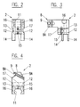
- the fastening element 2 has a head 8 which fits into the fastening profile and has two lateral grooves 8A, see FIG. 4, through which a thread 9 is arranged, in which a grub screw 10 rotates, see FIG. 1, around the fastening element in the profile 4.1. 4.4 to be able to attach.
- the fastening element On the side opposite the head 8, the fastening element has a polygonal recess 11, which serves to receive a correspondingly shaped, polygonal rod, see for example FIGS. 7-11.
- Fig. 2 shows the view of the fastener according to FIG. 4 from the front, in the drawing from below, and you can see in the middle of the fastener two millings 12 with a through hole 13, which is to secure a slide to be described below for fastening of certain facade elements.
- two feet 14, which also perform a fastening and retention function for certain facade elements Perpendicular to the longitudinal extension of the bore 13, in the middle between the two feet 14, there is a thread 15 which, in connection with the embodiment according to FIG. 7, serves to receive an adjusting screw.
- FIG. 3 shows a rounded recess 16 which, in connection with the embodiment of FIG. 12, serves to receive connecting pins. It can also be seen that a spring 18 is arranged in the bore 17, the function of which is described below.
- the two legs 26 are connected by a flange 28, which has a bulge 29 in the middle, to which a pin 30 is fastened, which engages in the bore 17 with the compression spring 18 and is acted upon by this compression spring to the slide against the Profile rail, or to press the other end 23 of the facade element.
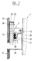
- FIG. 7 shows the use of the profile rail and the fastening element for fastening composite panels 31 with an aluminum frame.
- the aluminum frame has a hook-shaped part 32 at its lower end, which has an approximately U-shaped part 33 at its end, while the other, upper end 34 is approximately Z-shaped and whose outer end 35 is also bent in a U-shape .
- a rod 36 is used to fasten the facade element, the polygonal outer shape of which corresponds to the polygonal recess 11 in the fastening element, see FIG. 4, and which is slidable in this recess.
- the rod 36 has a tab 37 into which a screw 38, which fits into the bore 15, is inserted, see FIG. 2.
- An intermediate ring 39 is fastened to the screw 38, so that when the screw 38 is turned, the rod 36 can be moved up or down, as indicated by the dash-dotted lines of the rod.
- the screw 38 To hang a facade element, the screw 38 must be in the lower, i.e. dash-dotted position, and then the facade element can first be brought with its upper end 35 behind and to the fastener, whereupon the lower end is tilted, the small bent leg of the U-shaped end 33 gets behind the rod. Then the screw 38 is rotated and the rod is brought into the end position shown in FIG. 7, whereby the facade element is held and secured against falling out.
- the additional rail 40 is fastened to the fastening element 2 with the rod 36 without a lug, the latter being pushed through the polygonal recess 11.
- the symmetrically constructed additional rail consists of a central, rectangular tubular part 40M, the long side 41 facing the masonry is closed and the other long side 42 facing the facade element is open and elongated on both sides, so that the Total height of the additional rail corresponds to the length of the rod 36.
- the two transverse sides 43 have an angled part 44, the distance between the long side 41 on the wall side and the angled part 44 of the transverse sides corresponding to the diameter of the rod 36, so that the additional rail clings firmly to the rod.
- the dimensions of the rod 36 and the corresponding opening 11 in the fastening part are coordinated with one another in such a way that the rod cannot slide down even when loaded by the additional rail.
- the profiled sheet 45 is fastened to the additional rail by means of rivets 46. This type of fastening enables length compensation due to thermal expansion, since the additional rail is fixed on the fastening rod 36, but is not immovably fastened thereon. This is of great advantage in particular for long lengths of, for example, up to 6 m, both of the additional rail and of the profiled sheets.
- composite panels 47 with plastic fastening frames 48 are fastened to the additional rail 40, whereby arrow-shaped locking elements 49 made of a rubber-elastic material press barbs 50 in the fastening frame behind the angled legs 51 at the opening of the longitudinal wall 41 on the wall, and thus these composite panels to the Fasten the additional rail.
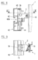
- FIGS. 12 and 13 shows a further type of fastening of other facade elements with the fastening element 2.
- the facade elements 52 have correspondingly shaped transverse walls 53 on both sides, on which the facade elements are suspended.
- its uppermost part is connected directly to the profile rail 1 or to the masonry via a rivet 54.
- the facade elements are suspended from horizontal bolts 55, see FIG. 13, these bolts being inserted in the rounded recess 16 of the fastening element 2.
- the transverse walls 53 are cut out so that they can be easily attached to the bolts in such a way that the facade elements are not rigid but are suspended are to enable length compensation due to temperature fluctuations.
- the material of the various fastening elements on the one hand and of the different and previously described facade elements on the other hand was not specifically enumerated, since it is not the focus of the essence of the invention.
- the facade elements are metallic elements, i.e. around galvanized sheet or aluminum sheet or the like, but the invention is not restricted to these materials.
- Both the profile rails and the additional rails and the fastening elements can preferably be produced from die-cast aluminum, but even there the invention is not restricted to this material.
- the fastening system consisting of a profiled rail and fastening element, enables the fastening of a large number of facade elements which, according to the prior art, would otherwise each require a special fastening system.
- this fastening system according to the invention enables rapid assembly of the elements and a length compensation that was not possible until then as a result of temperature fluctuations of the facade elements.
Landscapes
- Engineering & Computer Science (AREA)
- Architecture (AREA)
- Civil Engineering (AREA)
- Structural Engineering (AREA)
- Finishing Walls (AREA)
Applications Claiming Priority (2)
| Application Number | Priority Date | Filing Date | Title |
|---|---|---|---|
| CH1097/94 | 1994-04-13 | ||
| CH109794 | 1994-04-13 |
Publications (1)
| Publication Number | Publication Date |
|---|---|
| EP0677626A1 true EP0677626A1 (fr) | 1995-10-18 |
Family
ID=4202412
Family Applications (1)
| Application Number | Title | Priority Date | Filing Date |
|---|---|---|---|
| EP95810216A Withdrawn EP0677626A1 (fr) | 1994-04-13 | 1995-04-03 | Dispositif de fixation de murs-videaux à ventilation arrière |
Country Status (3)
| Country | Link |
|---|---|
| EP (1) | EP0677626A1 (fr) |
| FI (1) | FI951709A7 (fr) |
| NO (1) | NO305135B1 (fr) |
Cited By (1)
| Publication number | Priority date | Publication date | Assignee | Title |
|---|---|---|---|---|
| AT410457B (de) * | 1999-07-26 | 2003-05-26 | Wiesner Hager Baugruppe Gmbh | Vorrichtung zum befestigen von hinterlüfteten fassadenplatten |
Citations (7)
| Publication number | Priority date | Publication date | Assignee | Title |
|---|---|---|---|---|
| GB1125123A (en) * | 1965-09-01 | 1968-08-28 | Jules Scott Zibell | Improved building system for attaching panels to structural supports |
| LU68748A1 (fr) * | 1972-11-07 | 1974-01-18 | ||
| FR2458647A1 (fr) * | 1979-06-13 | 1981-01-02 | Technal International Sa | Dispositif de fixation de plaques de parement notamment de plaques de marbre |
| EP0227514A1 (fr) * | 1985-11-08 | 1987-07-01 | Aluminium Alcan De France | Système support d'éléments d'habillage de façade, en particulier de caissons en tôle pliée |
| DE8621152U1 (de) * | 1986-08-07 | 1987-12-03 | Christian Pohl GmbH, 5000 Köln | Aus einzelnen Konstruktionselementen bestehender Bausatz für Wand- oder Deckenbekleidungen an Bauwerken |
| DE9005874U1 (de) * | 1990-05-23 | 1990-07-26 | Wagner, Peter, Dipl.-Ing., 3303 Vechelde | Fassade |
| EP0605988A2 (fr) * | 1993-01-06 | 1994-07-13 | Hunter Douglas Industries B.V. | Un élément de support |
-
1995
- 1995-04-03 EP EP95810216A patent/EP0677626A1/fr not_active Withdrawn
- 1995-04-10 FI FI951709A patent/FI951709A7/fi unknown
- 1995-04-11 NO NO951414A patent/NO305135B1/no unknown
Patent Citations (7)
| Publication number | Priority date | Publication date | Assignee | Title |
|---|---|---|---|---|
| GB1125123A (en) * | 1965-09-01 | 1968-08-28 | Jules Scott Zibell | Improved building system for attaching panels to structural supports |
| LU68748A1 (fr) * | 1972-11-07 | 1974-01-18 | ||
| FR2458647A1 (fr) * | 1979-06-13 | 1981-01-02 | Technal International Sa | Dispositif de fixation de plaques de parement notamment de plaques de marbre |
| EP0227514A1 (fr) * | 1985-11-08 | 1987-07-01 | Aluminium Alcan De France | Système support d'éléments d'habillage de façade, en particulier de caissons en tôle pliée |
| DE8621152U1 (de) * | 1986-08-07 | 1987-12-03 | Christian Pohl GmbH, 5000 Köln | Aus einzelnen Konstruktionselementen bestehender Bausatz für Wand- oder Deckenbekleidungen an Bauwerken |
| DE9005874U1 (de) * | 1990-05-23 | 1990-07-26 | Wagner, Peter, Dipl.-Ing., 3303 Vechelde | Fassade |
| EP0605988A2 (fr) * | 1993-01-06 | 1994-07-13 | Hunter Douglas Industries B.V. | Un élément de support |
Cited By (1)
| Publication number | Priority date | Publication date | Assignee | Title |
|---|---|---|---|---|
| AT410457B (de) * | 1999-07-26 | 2003-05-26 | Wiesner Hager Baugruppe Gmbh | Vorrichtung zum befestigen von hinterlüfteten fassadenplatten |
Also Published As
| Publication number | Publication date |
|---|---|
| NO305135B1 (no) | 1999-04-06 |
| FI951709A7 (fi) | 1995-10-14 |
| NO951414L (no) | 1995-10-16 |
| NO951414D0 (no) | 1995-04-11 |
| FI951709A0 (fi) | 1995-04-10 |
Similar Documents
| Publication | Publication Date | Title |
|---|---|---|
| EP2009293B1 (fr) | Dispositif destiné à lier un rail de profilé avec un autre composant | |
| DE2618442C2 (de) | Stütze für ein Geländer oder dergleichen | |
| DE8715256U1 (de) | Montageschieneneinheit | |
| EP1804008A1 (fr) | Dispositif de fixation des objets, notamment des capteurs solaires ou photovoltaïques, sur une toiture en tôle | |
| DE2059829A1 (de) | Struktursystem fuer den Zusammenbau von vorgefertigten Konstruktionen | |
| DE3232106A1 (de) | Tragschiene oder -platte fuer eine vorgehaengte wand- oder deckenverkleidung | |
| DE1801913A1 (de) | Anordnung von Beschlagteilen in Profilrahmen von Fenstern,Tueren od.dgl. | |
| EP3241974B1 (fr) | Système pour un joint d'étanchéité, en particulier pour un joint de seuil ou pour un joint de sol s'abaissant automatiquement | |
| DE2407196B2 (de) | Treibstangenbeschlag für Fenster, Türen o.dgl., insbesondere mit Kunststoff-Flügelrahmen | |
| DE2451813A1 (de) | Zargenbefestigungseinrichtung | |
| DE1683548A1 (de) | Fixier-,Justier- und Verbindungssystem fuer Rahmen,Platten oder Scheiben | |
| DE3107725A1 (de) | Isolierende verbindungsvorrichtung fuer bauplatten, insbesondere glasscheiben tragende zweiteilige metallrahmen | |
| DE102011085188A1 (de) | Halteklemme und Montagesystem zum Befestigen eines oder mehrerer Flächenelemente an einem Gebäude | |
| DE102008055954B4 (de) | Klemmbefestigung von Profilen auf Stehfalz- oder Trapezblechen | |
| EP0882898A1 (fr) | Dispositif d'ancrage | |
| EP1353021B1 (fr) | Dispositif pour l'attachement amovible d'un rail profilé à une paroi | |
| EP2108774B1 (fr) | Charnière | |
| DE19851013C1 (de) | Einrichtung zur Befestigung eines Profils | |
| DE10248168B4 (de) | Abdichtung für Maueröffnungen | |
| DE9212546U1 (de) | Rohrgestell | |
| DE102017000924A1 (de) | Plattenhalter | |
| DE19916236B4 (de) | Gebäudefassade | |
| DE102005053650B3 (de) | Scharnierbeschlag | |
| EP2562340A1 (fr) | Armature | |
| DE102007004490A1 (de) | Fassaden- oder Wandverkleidungssystem |
Legal Events
| Date | Code | Title | Description |
|---|---|---|---|
| PUAI | Public reference made under article 153(3) epc to a published international application that has entered the european phase |
Free format text: ORIGINAL CODE: 0009012 |
|
| AK | Designated contracting states |
Kind code of ref document: A1 Designated state(s): AT BE CH DE DK ES FR GB IE IT LI LU NL PT SE |
|
| 17P | Request for examination filed |
Effective date: 19960415 |
|
| 17Q | First examination report despatched |
Effective date: 19980918 |
|
| GRAG | Despatch of communication of intention to grant |
Free format text: ORIGINAL CODE: EPIDOS AGRA |
|
| GRAG | Despatch of communication of intention to grant |
Free format text: ORIGINAL CODE: EPIDOS AGRA |
|
| GRAG | Despatch of communication of intention to grant |
Free format text: ORIGINAL CODE: EPIDOS AGRA |
|
| GRAH | Despatch of communication of intention to grant a patent |
Free format text: ORIGINAL CODE: EPIDOS IGRA |
|
| RTI1 | Title (correction) |
Free format text: A DEVICE FOR SECURING REAR VENTILATED SUSPENDED FACADES |
|
| GRAH | Despatch of communication of intention to grant a patent |
Free format text: ORIGINAL CODE: EPIDOS IGRA |
|
| STAA | Information on the status of an ep patent application or granted ep patent |
Free format text: STATUS: THE APPLICATION IS DEEMED TO BE WITHDRAWN |
|
| 18D | Application deemed to be withdrawn |
Effective date: 20001031 |