EP0677698A1 - Dispositif de verrouillage pour lampe - Google Patents
Dispositif de verrouillage pour lampe Download PDFInfo
- Publication number
- EP0677698A1 EP0677698A1 EP95105267A EP95105267A EP0677698A1 EP 0677698 A1 EP0677698 A1 EP 0677698A1 EP 95105267 A EP95105267 A EP 95105267A EP 95105267 A EP95105267 A EP 95105267A EP 0677698 A1 EP0677698 A1 EP 0677698A1
- Authority
- EP
- European Patent Office
- Prior art keywords
- lamp
- edge
- luminaire
- housing
- closures
- Prior art date
- Legal status (The legal status is an assumption and is not a legal conclusion. Google has not performed a legal analysis and makes no representation as to the accuracy of the status listed.)
- Granted
Links
Images



Classifications
-
- F—MECHANICAL ENGINEERING; LIGHTING; HEATING; WEAPONS; BLASTING
- F21—LIGHTING
- F21V—FUNCTIONAL FEATURES OR DETAILS OF LIGHTING DEVICES OR SYSTEMS THEREOF; STRUCTURAL COMBINATIONS OF LIGHTING DEVICES WITH OTHER ARTICLES, NOT OTHERWISE PROVIDED FOR
- F21V31/00—Gas-tight or water-tight arrangements
- F21V31/005—Sealing arrangements therefor
-
- F—MECHANICAL ENGINEERING; LIGHTING; HEATING; WEAPONS; BLASTING
- F21—LIGHTING
- F21V—FUNCTIONAL FEATURES OR DETAILS OF LIGHTING DEVICES OR SYSTEMS THEREOF; STRUCTURAL COMBINATIONS OF LIGHTING DEVICES WITH OTHER ARTICLES, NOT OTHERWISE PROVIDED FOR
- F21V17/00—Fastening of component parts of lighting devices, e.g. shades, globes, refractors, reflectors, filters, screens, grids or protective cages
- F21V17/10—Fastening of component parts of lighting devices, e.g. shades, globes, refractors, reflectors, filters, screens, grids or protective cages characterised by specific fastening means or way of fastening
- F21V17/16—Fastening of component parts of lighting devices, e.g. shades, globes, refractors, reflectors, filters, screens, grids or protective cages characterised by specific fastening means or way of fastening by deformation of parts; Snap action mounting
- F21V17/164—Fastening of component parts of lighting devices, e.g. shades, globes, refractors, reflectors, filters, screens, grids or protective cages characterised by specific fastening means or way of fastening by deformation of parts; Snap action mounting the parts being subjected to bending, e.g. snap joints
Definitions
- the invention relates to a luminaire with at least one elongated lamp arranged in a luminaire housing, a lamp luminaire spanning the lamp and closing, transparent or translucent luminaire trough with a peripheral edge, in particular claw rim, which is detachably connected to the luminaire housing via a plurality of closures.
- a lamp known on the market has an undercut of the lamp housing, which extends over the entire length of the side edge, which undercuts the edge of the lamp trough, which acts as a claw edge, i.e. outwardly bent edge is also overlaps over the entire length.
- a disadvantage of this lamp is considered that the lamp can be opened again only with difficulty, especially if it exceeds a certain length.
- lights are known in which several snap locks are articulated on the light housing, which can be hung on the edge of the tub, which must have a claw edge for this purpose, and can then be folded down into a closed position.
- a lamp with such closures can be opened more easily, these closures are complicated to manufacture on the one hand, on the other hand, the lamp housing must be provided with receptacles specially designed for these closures, into which the closures are hung or clipped.
- the substantially vertical edge of the lamp housing has one part of the closure, usually in the form of a molded hook, and the edge of the lamp trough has the other part of the closure, so that the two parts of the closures are inserted into one another by plugging the lamp trough onto the lamp housing can be locked together.
- the luminaire trough which generally consists of a very brittle material, for example polymethyl methacrylate, must be provided with the closure part and can therefore no longer be produced, for example, by simple thermoforming.
- the closure parts When attaching the luminaire trough to the luminaire housing or when loosening, the closure parts are subjected to bending loads, so that there is a risk that the closure part of the luminaire trough consisting of a brittle material will be damaged. If one of these locking parts is damaged, the luminaire tray can only be insufficiently attached to the luminaire housing; in particular, the dust and splash water tightness that may be present in a fully functional luminaire is then no longer ensured.
- the invention is therefore based on the object of providing a lamp with closures, no additional component being required for this, these being as simple as possible to use and the risk of damage to the lamp tub being small due to mechanical stresses on the closures being small.
- the lamp housing has a circumferential standing edge and a groove lying opposite it, and in that the closures are integrally formed on the circumferential standing edge and protrude into the groove receiving the edge of the lamp trough in such a way that when the lamp trough is inserted, they follow it overlap the outside curved edge.
- closures are integrated into the lamp housing, so that no additional components are required and the closures can be produced together with the lamp housing as an injection molded part.
- the closures are only provided on the lamp housing, so that the lamp tray has no special components that could be excessively stressed when closing and opening the lamp.
- the tub housing is made of a tough material, such as polycarbonate. Therefore, the closures can be deformed to a certain extent without the risk of damage.
- a handle can be provided on the closure, which protrudes beyond the standing edge. This means that both the locking point is marked for the installer and it is easier to operate.
- the closures are preferably provided evenly distributed over the circumference or over the side lengths of the lamp housing. As a result of this even distribution of the closures, the mechanical load on the luminaire trough is evenly distributed over its entire circumference and the edge of the luminaire trough is held evenly in the circumferential groove of the luminaire housing.
- a sealing tape is inserted into the groove of the lamp housing.
- the edge of the lamp trough is pressed against the sealing tape by the overlapping closures. Thanks to this seal, the luminaire can also be used as a damp room luminaire.
- At least two further receiving devices are integrally formed on the closures or on the standing edge on the same side length of the lamp housing, into which the edge of the lamp trough can be hung when the lamp is open.
- These receptacles can be integrated on a closure as well as molded onto the standing edge at another point, if this is desirable or necessary for reasons of stability.
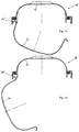
- the luminaire 10 consists of a luminaire housing 12, a transparent or translucent luminaire trough 14 which closes the luminaire housing and has a circumferential edge 16.
- the luminaire housing 12 has a circumferential standing edge 18, 18 'and a groove 20 lying deeper in relation to this, into which a sealing strip 22 is inserted.
- Closures 24, 24 ' are integrally formed on the standing edge 18, 18', which are formed from formations 26, 26 'of the standing edge 18, 18', locking hooks 28, 28 'formed thereon and grip tabs 30, 30'. Several of these closures 24, 24 'are evenly distributed on the two opposite side lengths of the lamp housing.
- Luminaires are provided on the inside of the luminaire housing along the groove 20, distributed over the circumference of centering webs 32, 32 '.
- the shape 26 of the closures 24 lying on one side length is bent in the direction of the arrow until the edge 16 is completely released.
- the sealing strip presses the edge of the lamp tray out of the groove 20, so that the locking lug 28 cannot overlap the edge 16 again.
- the closures 24 lying on the same long side, not shown in section, can thus be opened effortlessly one after the other.
- a tough plastic material polycarbonate
- the required deformation of the formation 26 shown is possible without damage
- Luminaire tray 14 can be removed from the closures 24 '.
- the reverse procedure can be used to close the lamp 10.
- the lamp trough 14 is inserted into the closures 24 'on one side length of the lamp housing 12, then the lamp trough is guided to the closures 24 on the opposite side by a rotary movement in these closures 24'.
- closing the formation 26 does not have to be bent as shown in Fig. 1b, but the edge 16 is pressed against the inclined plane 34 of the locking hook 28 and bends the formation 26 so far that the edge 16 can be inserted into the groove 20 .
- closures 24, 24 ' also allows simultaneous, vertical insertion of the lamp tray, in which both the closures 24 and the opposing closures 24' are pressed over the inclined plane 34, 34 'of the latching hooks 28, 28' and Edge 16 can be inserted into the groove 20.
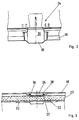
- FIG. 2 shows a broken side view of a closure 24 by way of illustration.
- the molded portions 26, 26 ' are integrally formed on the standing edge 18.
- the grip nose 30 protrudes in a trapezoidal shape beyond the standing edge 18 and thus additionally identifies the closure for the user and thus the point at which a latching hook 28 (FIG. 1) projects into the groove 20 (FIG. 1).
- Fig. 3 shows a broken plan view of a closure area in which the elongated shape of the centering webs 32 can be seen.
- the shape 26 also protrudes laterally beyond the standing edge 18 in order to create additional space for the locking lug 28 here with almost the same material thickness.
- the groove 20 also tapers, which on the one hand achieves an additional clamping effect for the sealing tape 22 and on the other hand creates space for an opening 36 in which a plunger core lies during the manufacture of the luminaire housing 12. This enables the closure 24 and its locking lug 28 to be shaped with simple tools and complicated slides, among other things. avoided.
- additional receptacle 40 is integrally formed on the closures 24 ', which essentially consists of an L-shaped hook 41 directed towards the center of the lamp housing, between the leg 42 of the hook and the shape 26 'of the closure 24' a slot is formed, into which the edge 16 of the lamp tray 14 can be inserted.
- the receiving devices 40 can also be molded onto areas of the standing edge 18 where there are no closures, since, as can be seen from FIG. 3, the standing edge at the closing points is only insignificantly thicker and therefore the position of the receiving device does not depend on the position of the closure is.
- This receiving device 40 is used to mount the lamp trough 14 in the open state of the lamp 10 during assembly or maintenance work on the lamp 10, for example when mounting on the ceiling.
- the edge 16 of the lamp trough 14 is inserted into the slot remaining between the L-shaped hook 41 and the formation 26 ', and then turned downwards.
- the edge 16 engages behind the leg 42 of the receiving device 40, and depending on the weight of the lamp trough 14 and the bending stiffness of the receiving device, the latter can also be slightly bent open.
- 5 and 6 show a broken side view of a closure for clarification with molded receiving device or a broken top view.
- Fig. 6 it can be seen that the hook 41 is formed on the outside of the lamp housing 12 via oblique webs 44, 44 ', which emanate from the formation 26 and a slot for the formation 26 is formed by the leg 42.
- this type of shaping creates an opening 46 in which a plunger core lies when the lamp housing 12 is manufactured. This makes it possible to shape the receiving device 40 and its leg 42, which faces towards the inside, with simple tools and complicated slides, among other things. avoided.
Landscapes
- Engineering & Computer Science (AREA)
- General Engineering & Computer Science (AREA)
- Arrangement Of Elements, Cooling, Sealing, Or The Like Of Lighting Devices (AREA)
- Vessels And Coating Films For Discharge Lamps (AREA)
- Arrangements Of Lighting Devices For Vehicle Interiors, Mounting And Supporting Thereof, Circuits Therefore (AREA)
Applications Claiming Priority (2)
| Application Number | Priority Date | Filing Date | Title |
|---|---|---|---|
| DE4413316 | 1994-04-16 | ||
| DE4413316A DE4413316C2 (de) | 1994-04-16 | 1994-04-16 | Leuchtenverschluß |
Publications (2)
| Publication Number | Publication Date |
|---|---|
| EP0677698A1 true EP0677698A1 (fr) | 1995-10-18 |
| EP0677698B1 EP0677698B1 (fr) | 1999-03-10 |
Family
ID=6515682
Family Applications (1)
| Application Number | Title | Priority Date | Filing Date |
|---|---|---|---|
| EP95105267A Expired - Lifetime EP0677698B1 (fr) | 1994-04-16 | 1995-04-07 | Lampe |
Country Status (4)
| Country | Link |
|---|---|
| EP (1) | EP0677698B1 (fr) |
| AT (1) | ATE177522T1 (fr) |
| DE (2) | DE4413316C2 (fr) |
| ES (1) | ES2130461T3 (fr) |
Cited By (8)
| Publication number | Priority date | Publication date | Assignee | Title |
|---|---|---|---|---|
| GB2322441A (en) * | 1997-02-20 | 1998-08-26 | Illuma Lighting Ltd | Luminaires |
| WO1999017054A1 (fr) * | 1997-09-26 | 1999-04-08 | Showers International Pty. Ltd. | Boitier de securite pour tubes d'eclairage |
| GB2335264A (en) * | 1998-03-10 | 1999-09-15 | Rewires | Container with snap-action lid suitable for an exterior light |
| EP0982536A3 (fr) * | 1998-08-28 | 2002-04-03 | CEAG Sicherheitstechnik GmbH | Ensemble d'éléments pour la formation de lampes |
| US8292475B2 (en) | 2009-09-01 | 2012-10-23 | D Alelio John R | Method for enhancing the frictional grip of a clip-on lampshade |
| GB2503732A (en) * | 2012-07-06 | 2014-01-08 | Thorpe F W Plc | Luminaire diffuser arrangement |
| CN108119872A (zh) * | 2018-01-17 | 2018-06-05 | 江苏普森帝照明有限公司 | 一种灯具锁固装置 |
| CN111043574A (zh) * | 2019-11-20 | 2020-04-21 | 宁波三防照明科技有限公司 | 一种灯座与灯罩的快速扣合装置 |
Families Citing this family (4)
| Publication number | Priority date | Publication date | Assignee | Title |
|---|---|---|---|---|
| DE19741240B4 (de) * | 1997-09-18 | 2004-04-15 | Fränkische Leuchten GmbH | Leuchtenteilgehäuse zur Herstellung eines Leuchtengehäuses |
| DE20019813U1 (de) | 2000-11-22 | 2001-02-22 | Reiss International GmbH, 88069 Tettnang | Leuchte |
| DE10134795B4 (de) * | 2001-07-11 | 2012-03-29 | Reiss Lighting Gmbh | Leuchte |
| DE102018001189A1 (de) * | 2018-02-16 | 2019-08-22 | Trilux Gmbh & Co. Kg | Leuchte, insbesondere Feuchtraumleute |
Citations (3)
| Publication number | Priority date | Publication date | Assignee | Title |
|---|---|---|---|---|
| CH477650A (de) * | 1966-12-16 | 1969-08-31 | Siemens Ag | Leuchte mit einem Leuchtengehäuse, dessen zwei Gehäuseteile scharnierartig verbunden sind |
| FR2071225A5 (fr) * | 1969-12-22 | 1971-09-17 | Eta | |
| EP0199230A2 (fr) * | 1985-04-16 | 1986-10-29 | ABB CEAG Licht- und Stromversorgungstechnik GmbH | Lampe, en particulier pour éclairage de secours |
Family Cites Families (5)
| Publication number | Priority date | Publication date | Assignee | Title |
|---|---|---|---|---|
| DE1919188U (de) * | 1965-02-26 | 1965-07-08 | Siemens Ag | Leuchte mit loesbaren und scharnierartigen verschlusselementen. |
| US3360644A (en) * | 1965-06-30 | 1967-12-26 | Lillebostad Ottar | Detachable watertight connection between a lighting fixture top part and plastic shade |
| DE8024546U1 (de) * | 1980-09-13 | 1981-05-27 | Philips Patentverwaltung Gmbh, 2000 Hamburg | Deckenleuchte mit einem aus elastischem kunststoff bestehenden zweiteiligen gehaeuse |
| DE8326661U1 (de) * | 1983-09-16 | 1985-02-28 | Robert Bosch Gmbh, 7000 Stuttgart | Scheinwerfer fuer insbesondere kraftfahrzeuge |
| DE8431426U1 (de) * | 1984-10-26 | 1985-02-28 | ITT Reiss International GmbH, 7992 Tettnang | Feuchtraumleuchte |
-
1994
- 1994-04-16 DE DE4413316A patent/DE4413316C2/de not_active Expired - Fee Related
-
1995
- 1995-04-07 AT AT95105267T patent/ATE177522T1/de not_active IP Right Cessation
- 1995-04-07 EP EP95105267A patent/EP0677698B1/fr not_active Expired - Lifetime
- 1995-04-07 DE DE59505236T patent/DE59505236D1/de not_active Expired - Fee Related
- 1995-04-07 ES ES95105267T patent/ES2130461T3/es not_active Expired - Lifetime
Patent Citations (3)
| Publication number | Priority date | Publication date | Assignee | Title |
|---|---|---|---|---|
| CH477650A (de) * | 1966-12-16 | 1969-08-31 | Siemens Ag | Leuchte mit einem Leuchtengehäuse, dessen zwei Gehäuseteile scharnierartig verbunden sind |
| FR2071225A5 (fr) * | 1969-12-22 | 1971-09-17 | Eta | |
| EP0199230A2 (fr) * | 1985-04-16 | 1986-10-29 | ABB CEAG Licht- und Stromversorgungstechnik GmbH | Lampe, en particulier pour éclairage de secours |
Cited By (11)
| Publication number | Priority date | Publication date | Assignee | Title |
|---|---|---|---|---|
| GB2322441A (en) * | 1997-02-20 | 1998-08-26 | Illuma Lighting Ltd | Luminaires |
| GB2322441B (en) * | 1997-02-20 | 2000-09-13 | Illuma Lighting Ltd | Luminaires |
| WO1999017054A1 (fr) * | 1997-09-26 | 1999-04-08 | Showers International Pty. Ltd. | Boitier de securite pour tubes d'eclairage |
| GB2335264A (en) * | 1998-03-10 | 1999-09-15 | Rewires | Container with snap-action lid suitable for an exterior light |
| GB2335264B (en) * | 1998-03-10 | 2002-04-17 | Rewires | Container with snap-action lid |
| EP0982536A3 (fr) * | 1998-08-28 | 2002-04-03 | CEAG Sicherheitstechnik GmbH | Ensemble d'éléments pour la formation de lampes |
| US8292475B2 (en) | 2009-09-01 | 2012-10-23 | D Alelio John R | Method for enhancing the frictional grip of a clip-on lampshade |
| GB2503732A (en) * | 2012-07-06 | 2014-01-08 | Thorpe F W Plc | Luminaire diffuser arrangement |
| CN108119872A (zh) * | 2018-01-17 | 2018-06-05 | 江苏普森帝照明有限公司 | 一种灯具锁固装置 |
| CN108119872B (zh) * | 2018-01-17 | 2024-05-14 | 江苏普森帝照明有限公司 | 一种灯具锁固装置 |
| CN111043574A (zh) * | 2019-11-20 | 2020-04-21 | 宁波三防照明科技有限公司 | 一种灯座与灯罩的快速扣合装置 |
Also Published As
| Publication number | Publication date |
|---|---|
| ATE177522T1 (de) | 1999-03-15 |
| EP0677698B1 (fr) | 1999-03-10 |
| ES2130461T3 (es) | 1999-07-01 |
| DE59505236D1 (de) | 1999-04-15 |
| DE4413316A1 (de) | 1995-10-19 |
| DE4413316C2 (de) | 1998-07-16 |
Similar Documents
| Publication | Publication Date | Title |
|---|---|---|
| EP1606867B1 (fr) | Dispositif de traversee de cable | |
| EP0677698B1 (fr) | Lampe | |
| EP0392136A2 (fr) | Armature lumineuse antidéflagrante | |
| EP0860321A2 (fr) | Dispositif de fixation de feu de véhicule | |
| DE10236500A1 (de) | Deckenleuchte mit einem länglichen Leuchtengehäuse | |
| DE3021850C2 (de) | Vorrichtung zum Haltern einer Abdeckwanne an einem Leuchtengehäuse | |
| DE69931568T2 (de) | Kippschalter | |
| DE69833174T2 (de) | Durchführungsvorrichtung, insbesondere für Gehäuse elektrischer Geräte | |
| DE2539299A1 (de) | Geraeteeinbaudose fuer installationskanaele | |
| DE3346749C2 (fr) | ||
| DE69635356T2 (de) | Elektrische Steckdose | |
| DE4432302C2 (de) | In ein Leuchtengehäuse einsetzbare Lampenbefestigungseinrichtung | |
| DE10351413C5 (de) | Leuchtengehäuse, insbesondere für eine Langfeldleuchte | |
| DE2529219C3 (de) | Langgestreckte Leuchte | |
| DE3132524C2 (de) | Gerätegehäuse, insbesondere für Elektrozaungeräte | |
| DE4316271C2 (de) | Beleuchtungsvorrichtung für Kleinstleuchtstofflampen | |
| DE4038055C1 (en) | Spreading claw fixture for flush fitting electrical appts.appts. - engages ribs and/or wall indentations facing each other on vertical sides of socket | |
| DE3145103C2 (de) | Elektrisches Installations-Schaltgerät mit aufsteckbarer Verkleidung | |
| DE10134795B4 (de) | Leuchte | |
| DE7801783U1 (de) | Fahrzeugleuchte, insbesondere kennzeichenleuchte | |
| DE3925633A1 (de) | Gehaeuse fuer instrumente | |
| EP0670243A2 (fr) | Unité d'éclairage pour véhicule | |
| CH679690A5 (fr) | ||
| EP0675583A1 (fr) | Matériel pour montage en surface d'un élément électrique tel qu'interrupteur, prise ou similaire | |
| DE1764535C3 (de) | Leuchte |
Legal Events
| Date | Code | Title | Description |
|---|---|---|---|
| PUAI | Public reference made under article 153(3) epc to a published international application that has entered the european phase |
Free format text: ORIGINAL CODE: 0009012 |
|
| AK | Designated contracting states |
Kind code of ref document: A1 Designated state(s): AT BE CH DE DK ES FR GB IT LI NL |
|
| 17P | Request for examination filed |
Effective date: 19951120 |
|
| 17Q | First examination report despatched |
Effective date: 19970507 |
|
| RAP1 | Party data changed (applicant data changed or rights of an application transferred) |
Owner name: REISS INTERNATIONAL GMBH |
|
| GRAG | Despatch of communication of intention to grant |
Free format text: ORIGINAL CODE: EPIDOS AGRA |
|
| GRAG | Despatch of communication of intention to grant |
Free format text: ORIGINAL CODE: EPIDOS AGRA |
|
| GRAH | Despatch of communication of intention to grant a patent |
Free format text: ORIGINAL CODE: EPIDOS IGRA |
|
| GRAH | Despatch of communication of intention to grant a patent |
Free format text: ORIGINAL CODE: EPIDOS IGRA |
|
| GRAA | (expected) grant |
Free format text: ORIGINAL CODE: 0009210 |
|
| AK | Designated contracting states |
Kind code of ref document: B1 Designated state(s): AT BE CH DE DK ES FR GB IT LI NL |
|
| PG25 | Lapsed in a contracting state [announced via postgrant information from national office to epo] |
Ref country code: NL Free format text: LAPSE BECAUSE OF FAILURE TO SUBMIT A TRANSLATION OF THE DESCRIPTION OR TO PAY THE FEE WITHIN THE PRESCRIBED TIME-LIMIT Effective date: 19990310 Ref country code: GB Free format text: LAPSE BECAUSE OF NON-PAYMENT OF DUE FEES Effective date: 19990310 |
|
| REF | Corresponds to: |
Ref document number: 177522 Country of ref document: AT Date of ref document: 19990315 Kind code of ref document: T |
|
| REG | Reference to a national code |
Ref country code: CH Ref legal event code: EP |
|
| PG25 | Lapsed in a contracting state [announced via postgrant information from national office to epo] |
Ref country code: AT Free format text: LAPSE BECAUSE OF NON-PAYMENT OF DUE FEES Effective date: 19990407 |
|
| REF | Corresponds to: |
Ref document number: 59505236 Country of ref document: DE Date of ref document: 19990415 |
|
| PG25 | Lapsed in a contracting state [announced via postgrant information from national office to epo] |
Ref country code: LI Free format text: LAPSE BECAUSE OF NON-PAYMENT OF DUE FEES Effective date: 19990430 Ref country code: CH Free format text: LAPSE BECAUSE OF NON-PAYMENT OF DUE FEES Effective date: 19990430 Ref country code: BE Free format text: LAPSE BECAUSE OF NON-PAYMENT OF DUE FEES Effective date: 19990430 |
|
| ITF | It: translation for a ep patent filed | ||
| PG25 | Lapsed in a contracting state [announced via postgrant information from national office to epo] |
Ref country code: DK Free format text: LAPSE BECAUSE OF FAILURE TO SUBMIT A TRANSLATION OF THE DESCRIPTION OR TO PAY THE FEE WITHIN THE PRESCRIBED TIME-LIMIT Effective date: 19990610 |
|
| REG | Reference to a national code |
Ref country code: ES Ref legal event code: FG2A Ref document number: 2130461 Country of ref document: ES Kind code of ref document: T3 |
|
| ET | Fr: translation filed | ||
| NLV1 | Nl: lapsed or annulled due to failure to fulfill the requirements of art. 29p and 29m of the patents act | ||
| GBV | Gb: ep patent (uk) treated as always having been void in accordance with gb section 77(7)/1977 [no translation filed] |
Effective date: 19990310 |
|
| BERE | Be: lapsed |
Owner name: REISS INTERNATIONAL G.M.B.H. Effective date: 19990430 |
|
| REG | Reference to a national code |
Ref country code: CH Ref legal event code: PL |
|
| PLBE | No opposition filed within time limit |
Free format text: ORIGINAL CODE: 0009261 |
|
| STAA | Information on the status of an ep patent application or granted ep patent |
Free format text: STATUS: NO OPPOSITION FILED WITHIN TIME LIMIT |
|
| 26N | No opposition filed | ||
| PGFP | Annual fee paid to national office [announced via postgrant information from national office to epo] |
Ref country code: FR Payment date: 20030417 Year of fee payment: 9 |
|
| PGFP | Annual fee paid to national office [announced via postgrant information from national office to epo] |
Ref country code: ES Payment date: 20030422 Year of fee payment: 9 |
|
| PGFP | Annual fee paid to national office [announced via postgrant information from national office to epo] |
Ref country code: DE Payment date: 20030624 Year of fee payment: 9 |
|
| PG25 | Lapsed in a contracting state [announced via postgrant information from national office to epo] |
Ref country code: ES Free format text: LAPSE BECAUSE OF NON-PAYMENT OF DUE FEES Effective date: 20040410 |
|
| PG25 | Lapsed in a contracting state [announced via postgrant information from national office to epo] |
Ref country code: DE Free format text: LAPSE BECAUSE OF NON-PAYMENT OF DUE FEES Effective date: 20041103 |
|
| PG25 | Lapsed in a contracting state [announced via postgrant information from national office to epo] |
Ref country code: FR Free format text: LAPSE BECAUSE OF NON-PAYMENT OF DUE FEES Effective date: 20041231 |
|
| REG | Reference to a national code |
Ref country code: FR Ref legal event code: ST |
|
| PG25 | Lapsed in a contracting state [announced via postgrant information from national office to epo] |
Ref country code: IT Free format text: LAPSE BECAUSE OF NON-PAYMENT OF DUE FEES Effective date: 20050407 |
|
| REG | Reference to a national code |
Ref country code: ES Ref legal event code: FD2A Effective date: 20040410 |