EP0677718A1 - Projectile destiné à agresser des cibles dures - Google Patents
Projectile destiné à agresser des cibles dures Download PDFInfo
- Publication number
- EP0677718A1 EP0677718A1 EP95400742A EP95400742A EP0677718A1 EP 0677718 A1 EP0677718 A1 EP 0677718A1 EP 95400742 A EP95400742 A EP 95400742A EP 95400742 A EP95400742 A EP 95400742A EP 0677718 A1 EP0677718 A1 EP 0677718A1
- Authority
- EP
- European Patent Office
- Prior art keywords
- charge
- projectile
- initiation
- impact
- explosive
- Prior art date
- Legal status (The legal status is an assumption and is not a legal conclusion. Google has not performed a legal analysis and makes no representation as to the accuracy of the status listed.)
- Granted
Links
- 239000002360 explosive Substances 0.000 claims abstract description 46
- 230000000977 initiatory effect Effects 0.000 claims abstract description 40
- 239000000463 material Substances 0.000 claims abstract description 17
- XAGFODPZIPBFFR-UHFFFAOYSA-N aluminium Chemical compound [Al] XAGFODPZIPBFFR-UHFFFAOYSA-N 0.000 claims abstract description 12
- 239000004567 concrete Substances 0.000 claims abstract description 9
- 239000004575 stone Substances 0.000 claims abstract description 8
- XTFIVUDBNACUBN-UHFFFAOYSA-N 1,3,5-trinitro-1,3,5-triazinane Chemical compound [O-][N+](=O)N1CN([N+]([O-])=O)CN([N+]([O-])=O)C1 XTFIVUDBNACUBN-UHFFFAOYSA-N 0.000 claims abstract description 7
- 229910052782 aluminium Inorganic materials 0.000 claims abstract description 6
- 239000011449 brick Substances 0.000 claims abstract description 6
- 230000004044 response Effects 0.000 claims abstract description 4
- 239000011248 coating agent Substances 0.000 claims description 18
- 238000000576 coating method Methods 0.000 claims description 18
- 230000000694 effects Effects 0.000 claims description 14
- 238000010304 firing Methods 0.000 claims description 7
- 239000000203 mixture Substances 0.000 claims description 3
- 239000000843 powder Substances 0.000 abstract description 2
- 239000004411 aluminium Substances 0.000 abstract 1
- 239000004020 conductor Substances 0.000 description 7
- 235000009854 Cucurbita moschata Nutrition 0.000 description 4
- 240000001980 Cucurbita pepo Species 0.000 description 4
- 235000009852 Cucurbita pepo Nutrition 0.000 description 4
- 230000004224 protection Effects 0.000 description 4
- 235000020354 squash Nutrition 0.000 description 4
- 239000002131 composite material Substances 0.000 description 3
- 229910052751 metal Inorganic materials 0.000 description 3
- 239000002184 metal Substances 0.000 description 3
- 239000000654 additive Substances 0.000 description 2
- 230000000996 additive effect Effects 0.000 description 2
- 238000001465 metallisation Methods 0.000 description 2
- 230000002093 peripheral effect Effects 0.000 description 2
- 230000037452 priming Effects 0.000 description 2
- 229910001369 Brass Inorganic materials 0.000 description 1
- 241000273930 Brevoortia tyrannus Species 0.000 description 1
- RYGMFSIKBFXOCR-UHFFFAOYSA-N Copper Chemical compound [Cu] RYGMFSIKBFXOCR-UHFFFAOYSA-N 0.000 description 1
- 238000004026 adhesive bonding Methods 0.000 description 1
- 230000015572 biosynthetic process Effects 0.000 description 1
- 239000010951 brass Substances 0.000 description 1
- 239000004566 building material Substances 0.000 description 1
- 239000003990 capacitor Substances 0.000 description 1
- 230000002301 combined effect Effects 0.000 description 1
- 230000006835 compression Effects 0.000 description 1
- 238000007906 compression Methods 0.000 description 1
- 229910052802 copper Inorganic materials 0.000 description 1
- 239000010949 copper Substances 0.000 description 1
- 238000010586 diagram Methods 0.000 description 1
- 239000011152 fibreglass Substances 0.000 description 1
- 238000013467 fragmentation Methods 0.000 description 1
- 238000006062 fragmentation reaction Methods 0.000 description 1
- 239000011810 insulating material Substances 0.000 description 1
- 229910001234 light alloy Inorganic materials 0.000 description 1
- 238000012423 maintenance Methods 0.000 description 1
- 238000000034 method Methods 0.000 description 1
- 238000005192 partition Methods 0.000 description 1
- 230000035515 penetration Effects 0.000 description 1
- 239000004033 plastic Substances 0.000 description 1
- 230000035939 shock Effects 0.000 description 1
- 230000006641 stabilisation Effects 0.000 description 1
- 238000011105 stabilization Methods 0.000 description 1
Images


Classifications
-
- F—MECHANICAL ENGINEERING; LIGHTING; HEATING; WEAPONS; BLASTING
- F42—AMMUNITION; BLASTING
- F42B—EXPLOSIVE CHARGES, e.g. FOR BLASTING, FIREWORKS, AMMUNITION
- F42B12/00—Projectiles, missiles or mines characterised by the warhead, the intended effect, or the material
- F42B12/02—Projectiles, missiles or mines characterised by the warhead, the intended effect, or the material characterised by the warhead or the intended effect
- F42B12/04—Projectiles, missiles or mines characterised by the warhead, the intended effect, or the material characterised by the warhead or the intended effect of armour-piercing type
- F42B12/10—Projectiles, missiles or mines characterised by the warhead, the intended effect, or the material characterised by the warhead or the intended effect of armour-piercing type with shaped or hollow charge
- F42B12/16—Projectiles, missiles or mines characterised by the warhead, the intended effect, or the material characterised by the warhead or the intended effect of armour-piercing type with shaped or hollow charge in combination with an additional projectile or charge, acting successively on the target
Definitions
- the field of the present invention is that of projectiles intended to attack hard structures of the type comprising for example structures of stone, brick, concrete or other building materials.
- Such targets are usually assigned to engineering teams who are responsible for placing explosives directly in contact with the structure.
- projectiles are known which are provided with means making it possible to distinguish targets according to their hardness.
- patent EP433254 describes a projectile comprising a double warhead contactor.
- a first contact is closed upon impact on a "soft" target, such as an aircraft or a light vehicle. This first contact causes the initiation of the charge after a certain delay, that is to say practically when the projectile is inside the target.
- a second contact is closed during impact on a "hard” target, ie a target that the projectile cannot pass through, this contact causes an immediate initiation of the explosive charge.
- Such a projectile is capable of distinguishing between a "soft” target such as a light vehicle or an aircraft and a “hard” target such as a tank, but it is ineffective against targets of the overprotected building or casemate type.
- the projectile proposed by the invention is capable of passing through peripheral protections such as sandbags to bring and initiate the explosive charge in contact with the hard structure itself.
- the subject of the invention is a projectile intended to attack hard targets such as stone, brick or concrete structures and comprising an explosive charge and means for initiating it, projectile characterized in that it comprises a penetrator , which deforms only on impact with a target of a given minimum mechanical resistance, and an internal impact switch disposed between the indenter and the charge, projectile comprising means ensuring the initiation of the charge in response when the internal contactor was crushed and after the explosive charge began to deform following impact on the target.
- the invention thus combines piercing means (the penetrator), which ensure the passage of the projectile through possible overprotections, and charge initiation means which determine an operation of the "squash head” type (initiation after crushing of the load) in contact with the structure.
- the explosive charge is a formed charge comprising a concave coating in contact with an explosive material and delimiting a cavity.
- Such a characteristic increases the anti-structure efficiency of the projectile and makes it possible to give it an anti-armored operating mode.
- the internal contactor is disposed in the cavity delimited by the coating, so that the contactor can only be closed after the load has started to deform following its impact on a target.
- the means ensuring the initiation of the load comprise a first delay actuated by the internal contactor.
- the explosive charge comprises at least one explosive material giving an enhanced blast effect during its initiation, for example an aluminum powder.
- the projectile comprises a ballistic warhead disposed in front of the penetrator and carrying an electrical contact actuated upon impact on a target.
- the projectile comprises a firing mode selector making it possible to choose between an initiation of the charge following the closing of the internal contactor and an initiation following the closing of the warhead contact.
- the overwriting of the warhead contact may cause initiation of the load by means of a second delay.
- a projectile 1 according to the invention comprises an explosive charge 2 placed inside a cylindrical envelope 3 made of light alloy, for example aluminum.
- the envelope 3 is closed at its rear part by a bottom 4 which carries stabilization fins 5 regularly distributed angularly.
- the fins are articulated on yokes 6 carried by the bottom 4 and are deployed when the projectile is fired from a recoilless launcher of known type and not shown.
- the explosive charge 2 is a formed charge comprising a concave coating 7 in contact with an explosive material.
- the coating delimits a cavity 8 which is here conical in shape.
- the explosive material will be chosen so as to generate, during its initiation, a reinforced blast effect, this in order to increase during the initiation the shock wave outside the concrete structures, which promotes their fragmentation.
- Such an explosive material also makes it possible to give an incendiary effect to the rear of targets of the armored or lightly armored vehicle type.
- an explosive comprising an finely divided reducing additive, such as a metallic powder, preferably an aluminum powder, will be chosen as the explosive.
- Hexal that is to say a mixture of hexogen and aluminum powder in the following proportions by mass: Hexogen 70% to 90%, Aluminum 30% to 10%.
- the explosive can be placed by compression in the casing 3 equipped with its coating or even be machined to its final dimensions and glued into the casing.
- the coating is made of a ductile material (for example copper), material capable of deforming so as to form a jet during the initiation of the explosive.
- a ductile material for example copper
- the coating is supported on a conical surface 9 arranged on an indenter 10.
- This support ensures the maintenance of the coating and the explosive charge during strong decelerations which occur on impact on sandbags.
- the indenter 10 is made of an impact-resistant material, for example aluminum.
- the profile of the penetrator is determined by a person skilled in the art so as to ensure crossing without deformation of the sandbags or other light protections. This profile is also defined so as not to withstand the impact on a hard structure such as concrete or stone.
- the indenter 10 carries at its rear part a shoulder 11 on which the casing 3 comes to bear.
- the envelope 3 is fixed to the penetrator 10 by gluing.
- Another fixing method could be adopted, for example radial pins or a screwing.
- the projectile 1 also includes a ballistic cap 12 made of light material, for example in fiberglass composite, and bonded to the penetrator 10.
- the cap is intended to give an aerodynamic profile to the projectile so as to reduce its loss of speed on its ballistic trajectory.
- the cover 12 comes to bear on the penetrator 10 at two shoulders, a rear shoulder 13 and a front shoulder 14.
- the cover 12 carries at its front part an electrical contact 15 which comprises in known manner a light metal cap 15a (for example made of brass) bonded to a bearing surface 16 of the cap and a metal layer 15b deposited on the front part of the cap.
- the contacts 15a and 15b are connected by conductors 17a and 17b to means 18 for initiating the explosive charge, means arranged in the bottom 4 and comprising in particular a primer 18a.
- the conductors 17a and 17b may for example be bonded to the external surface of the projectile 1.
- the projectile 1 finally comprises an internal contactor 19 which is disposed inside the cavity 8 delimited by the coating 7.
- the contactor comprises a support 20 made of insulating material (for example a plastic or composite material) and with a conical external profile which is glued to the covering 7.
- the support 20 carries a metallization 19b on a central part, as well as a light metal cap 19a bonded to a surface 21 of the support 20.
- the contacts 19a and 19b are connected to the priming means 18 by conductors 22a and 22b.
- the conductors must cross the load in a place such that they are not cut or destroyed before the contact 19 closes, they must therefore be behind the contactor in the direction of action of the projectile.
- the conductors 22 pass through the coating 7 at an axial hole 23 and also pass substantially axially through the explosive material of the charge 2.
- the establishment of the internal contactor 19 inside the cavity 8 delimited by the coating 7 has the effect of allowing it to be closed only when the load has started to deform following its impact on a target.
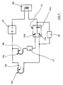
- FIG. 2 schematically shows the means for initiating the projectile according to the invention.
- a fire mode selector 24 which is preferably disposed outside the projectile and connected to the latter by conductors 25 (see FIG. 1). It will be mounted for example on the barrel of the weapon.
- the selector 24 makes it possible to choose between an "anti-structure” mode (in which the contacts 24a and 24b are connected) and an “anti-shielded” mode (in which the contacts 24a and 24c are connected).
- the "anti-structure" mode corresponds to a choice of the initiation of the explosive charge following the closing of the internal contactor 19.
- the "anti-armored" mode corresponds to a choice of the initiation of the explosive charge following the closure of the cover contact 15.
- the initiation means include an energy source 26 which may be constituted by a bootable battery or by one or more capacitors charged before firing.
- the electric primer 18a is connected on the one hand to the energy source 26 and on the other hand to the contact 24a of the firing mode selector.
- the metallizations 15b of the cap contact and 19b of the internal contactor are connected in parallel to the energy source 26.
- the conductive cap 15a of the cap contact is connected to the contact 24c of the firing mode selector 24.
- the conductive cap 19a of the internal contactor is connected to the contact 24b of the firing mode selector 24 by means of a first electronic delay 27 (which may possibly be omitted depending on the structure of the projectile as will be explained below. ).
- a second electronic delay 28 is arranged in parallel between the contacts 24a and 24c of the firing mode selector.
- the operation of the projectile is as follows.
- the shooter When the shooter wishes to destroy a structure (overprotected or not), he chooses the appropriate mode on the fire selector 24. When the projectile impacts on any external protections, the cap contact 15 closes which does not cause charge initiation but initiates delay 28.
- the ballistic cap 12 is destroyed by the first impact, but the penetrator 10 is sufficiently resistant and has a suitable profile to allow the crossing of overprotections (such as sandbags) without damage to the explosive charge.
- overprotections such as sandbags
- the coating 7 then comes into contact with the hard structure and its base is crushed in turn.
- the explosive charge deforms and the explosive placed at the base of the coating also crashes on the target.
- the internal contactor 15 is closed, which causes the initiation of the charge.
- the delay 27 can be omitted, since it is ensured that the load is crushed on the hard structure when the contactor 19 closes.
- the effect of the projectile according to the invention is therefore a combined effect which combines the formation of a jet by the undeformed part of the coating, and an overpressure effect due to the initiation of the explosive. crashed on the target ("Squash Head” effect).
- Simash Head effect
- Such a combination gives a particularly effective perforating effect on concrete, stone or brick structures.
- the delay 28 will be chosen so that it cannot cause the charge to be initiated before the contactor 19 is overwritten.
- the delay 28 has the function of ensuring self-destruction of the projectile in the event that it does not meet any structure hard likely to deform the indenter 10. We could for example choose a delay of the order of 5 to 20 milliseconds.
- This self-destruction also makes it possible to give the projectile an annoying effect against light targets such as road vehicles, light vehicles, aircraft or bunkers (ie light shelters formed by a simple stack of materials).
- the self-destruction mode also makes it possible, in the case where the penetrator does not meet a hard structure, to ensure an initiation of the projectile inside the overprotection which makes it possible to clear the latter with a view to a subsequent attack.
- the cap contact 15 closes, which causes an instantaneous initiation of the explosive charge at an optimal distance from the target, a distance defined in a known manner by the length of the cap. . This optimum distance allows the shaped charge jet to develop and have the best armor piercing performance.
- the projectile according to the invention therefore makes it possible, with a selector with two positions, to obtain three different operating modes: anti-armored, anti-structure, anti-light target.
- the projectile represented in FIG. 3 differs from that of FIG. 1 by the position given to the internal contactor 20.
- the latter is here glued to the interior of the internal cavity 29 of the indenter 10. Such an arrangement makes it easier to assemble by allowing the passage of the conductors 22a and 22b from the outside of the load 2.
- the internal contactor 20 can be given any axial position between the bottom of the internal cavity 29 of the indenter 10 and the bottom of the cavity 8 delimited by the coating 7, it will suffice to adjust the delay 27 accordingly.
- Such a projectile will have an anti-structure efficiency with a behavior of the type described above.
Landscapes
- Engineering & Computer Science (AREA)
- Chemical & Material Sciences (AREA)
- Combustion & Propulsion (AREA)
- General Engineering & Computer Science (AREA)
- Aiming, Guidance, Guns With A Light Source, Armor, Camouflage, And Targets (AREA)
Abstract
Description
- Le domaine de la présente invention est celui des projectiles destinés à agresser des structures dures du type comprenant par exemple des structures de pierre, brique, béton ou autres matériaux de construction.
- De telles cibles sont habituellement dévolues à des équipes du génie qui sont chargées de venir placer des explosifs directement au contact de la structure.
- Mais de telles opérations sont délicates à réaliser d'un point de vue tactique.
- On a cherché à définir des projectiles tirables à distance de sécurité et pouvant occasionner des dégâts notables à de telles cibles.
- Cependant ces-dernières sont le plus souvent protégées par une couche plus ou moins épaisse de sacs de sable qui provoque l'initiation des charges explosives habituelles à des distances de la structure de pierre ou de béton qui sont trop grandes pour que des dégâts importants lui soient occasionnés.
- On connaît par ailleurs des projectiles dotés de moyens permettant de distinguer les cibles suivant leur dureté.
- Ainsi le brevet EP433254 décrit un projectile comportant un double contacteur d'ogive. Un premier contact est fermé lors de l'impact sur une cible "molle", comme un aéronef ou un véhicule léger. Ce premier contact provoque l'initiation de la charge à l'issue d'un certain retard, c'est à dire pratiquement lorsque le projectile se trouve à l'intérieur de la cible.
- Un deuxième contact est fermé lors de l'impact sur une cible "dure", c'est à dire une cible que le projectile ne peut pas traverser, ce contact provoque une initiation immédiate de la charge explosive.
- Un tel projectile est capable de faire la distinction entre une cible "molle" comme un véhicule léger ou un aéronef et une cible "dure" telle un char, mais il est inefficace contre les cibles du type immeubles ou casemates surprotégés.
- En effet, la dureté de l'impact sur des surprotections comme des sacs de sable provoque l'initiation immédiate de la charge et à une distance trop importante de la structure de l'immeuble pour pouvoir lui occasionner un dommage.
- C'est un premier but de l'invention que de proposer un projectile de conception simple qui soit efficace contre les cibles dures telles les immeubles ou les casemates, même dotées de protections périphériques.
- A cet effet le projectile proposé par l'invention est capable de traverser les protections périphériques comme les sacs de sable pour venir amener et initier la charge explosive au contact même de la structure dure.
- C'est un autre but de l'invention que de proposer un tel projectile qui ait également une certaine efficacité contre les cibles blindées (comme les chars) et également une efficacité contre les cibles légères (comme les véhicules légers ou les aéronefs).
- Ainsi l'invention a pour objet un projectile destiné à agresser des cibles dures telles des structures de pierre, brique ou béton et comprenant une charge explosive et des moyens d'amorçage de celle-ci, projectile caractérisé en ce qu'il comporte un pénétrateur, qui ne se déforme qu'à l'impact avec une cible d'une résistance mécanique minimale donnée, et un contacteur d'impact interne disposé entre le pénétrateur et la charge, projectile comportant des moyens assurant l'initiation de la charge en réponse à l'écrasement du contacteur interne et après que la charge explosive ait commencé à se déformer consécutivement à l'impact sur la cible.
- L'invention combine ainsi des moyens perforants (le pénétrateur), qui assurent le passage du projectile au travers de surprotections éventuelles, et des moyens d'initiation de la charge qui déterminent un fonctionnement du type "squash head" (initiation après écrasement de la charge) au contact de la structure.
- Une telle combinaison donne au projectile une efficacité anti-structure supérieure à celle des projectiles connus.
- Selon une autre caractéristique, la charge explosive est une charge formée comprenant un revêtement concave au contact d'un matériau explosif et délimitant une cavité.
- Une telle caractéristique augmente l'efficacité anti-structure du projectile et permet de lui donner un mode de fonctionnement anti-blindé.
- Selon un mode de réalisation, le contacteur interne est disposé dans la cavité délimitée par le revêtement, de telle sorte que le contacteur ne puisse être fermé qu'après que la charge ait commencé à se déformer suite à son impact sur une cible.
- Selon un autre mode de réalisation, les moyens assurant l'initiation de la charge comprennent un premier retard actionné par le contacteur interne.
- Selon une variante d'exécution, la charge explosive comporte au moins un matériau explosif donnant un effet de souffle renforcé lors de son initiation, par exemple une poudre d'aluminium.
- On pourra par exemple choisir comme matériau explosif de la charge un mélange d'hexogène et de poudre d'aluminium dans les proportions en masse suivantes: Hexogène 70% à 90%, Aluminium 30% à 10%.
- Selon un autre mode de réalisation de l'invention, le projectile comporte une ogive balistique disposée en avant du pénétrateur et portant un contact électrique actionné lors de l'impact sur une cible.
- Avantageusement,le projectile comporte un sélecteur de mode de tir permettant de choisir entre une initiation de la charge consécutive à la fermeture du contacteur interne et une initiation suite à la fermeture du contact d'ogive.
- Dans ce cas, lorsque le sélecteur est positionné de façon à choisir le contact d'ogive, l'écrasement de ce dernier lors de l'impact sur une cible provoquera une initiation immédiate de la charge.
- Avantageusement, lorsque le sélecteur est positionné de façon à choisir le contacteur interne, l'écrasement du contact d'ogive pourra provoquer une initiation de la charge par l'intermédiaire d'un deuxième retard.
- L'invention sera mieux comprise à la lecture de la description qui va suivre de modes particuliers de réalisation, description faite en référence aux dessins annexés et dans lesquels:
- la figure 1 représente en coupe axiale un projectile selon un premier mode de réalisation de l'invention,
- la figure 2 est un schéma décrivant la structure des moyens d'initiation du projectile selon l'invention,
- la figure 3 représente le détail d'une variante de réalisation d'un projectile selon l'invention.
- En se reportant à la figure 1, un projectile 1 selon l'invention comprend une charge explosive 2 disposée à l'intérieur d'une enveloppe cylindrique 3 en alliage léger par exemple en aluminium.
- L'enveloppe 3 est fermée à sa partie arrière par un fond 4 qui porte des ailettes de stabilisation 5 régulièrement réparties angulairement. Les ailettes sont articulées sur des chapes 6 portées par le fond 4 et se déploient lors du tir du projectile à partir d'un lanceur sans recul de type connu et non représenté.
- La charge explosive 2 est une charge formée comprenant un revêtement concave 7 au contact d'un matériau explosif. Le revêtement délimite une cavité 8 qui est ici de forme conique.
- Le matériau explosif sera choisi de façon à engendrer lors de son initiation un effet de souffle renforcé, cela afin d'accroître lors de l'initiation l'onde de choc à l'extérieur des structures bétonnées ce qui favorise leur fragmentation. Un tel matériau explosif permet aussi de donner un effet incendiaire à l'arrière des cibles du type véhicules blindés ou légèrement blindés.
- On choisira par exemple comme explosif un explosif comportant un additif réducteur finement divisé, tel une poudre métallique de préférence une poudre d'aluminium.
- On pourra par exemple utiliser de l'Hexal, c'est à dire un mélange d'hexogène et de poudre d'aluminium dans les proportions en masse suivantes: Hexogène 70% à 90%, Aluminium 30% à 10%.
- L'explosif peut être mis en place par compression dans l'enveloppe 3 équipée de son revêtement ou encore être usiné à ses dimensions définitives et collé dans l'enveloppe.
- Il serait également possible d'utiliser d'autres types d'explosifs tels des explosifs composites et comportant un additif destiné à renforcer l'effet de souffle.
- Le revêtement est réalisé en un matériau ductile (par exemple en cuivre), matériau susceptible de se déformer de façon à former un jet lors de l'initiation de l'explosif.
- Le revêtement est en appui sur une portée conique 9 aménagée sur un pénétrateur 10.
- Cet appui permet d'assurer le maintien du revêtement et de la charge explosive lors des fortes décélérations qui interviennent à l'impact sur des sacs de sable.
- Le pénétrateur 10 est réalisée en un matériau résistant à l'impact, par exemple en aluminium.
- Il présente une forme externe profilée qui favorise la pénétration des surprotections légères (cloisons, sacs de sable).
- Le profil du pénétrateur est déterminé par l'homme du métier de façon à assurer une traversée sans déformation des sacs de sables ou autres protections légères. Ce profil est également défini de façon à ne pas résister à l'impact sur une structure dure telle que le béton ou la pierre.
- Le pénétrateur 10 porte à sa partie arrière un épaulement 11 sur lequel l'enveloppe 3 vient en appui. L'enveloppe 3 est fixée au pénétrateur 10 par collage. Un autre mode de fixation pourrait être adopté par exemple des goupilles radiales ou un vissage.
- La projectile 1 comporte aussi une coiffe balistique 12 réalisée en matériau léger, par exemple en composite de fibre de verre, et collée sur le pénétrateur 10. La coiffe est destinée à donner un profil aérodynamique au projectile de façon à réduire sa perte de vitesse sur sa trajectoire balistique.
- La coiffe 12 vient en appui sur le pénétrateur 10 au niveau de deux épaulements, un épaulement arrière 13 et un épaulement avant 14.
- La coiffe 12 porte à sa partie avant un contact électrique 15 qui comporte de façon connue une calotte métallique 15a légère (par exemple en laiton) collée sur une portée 16 de la coiffe et une couche métallique 15b déposée sur la partie avant de la coiffe. Les contacts 15a et 15b sont reliés par des conducteurs 17a et 17b à des moyens 18 d'amorçage de la charge explosive, moyens disposés dans le fond 4 et comportant notamment une amorce 18a.
- Les conducteurs 17a et 17b pourront par exemple être collés sur la surface externe du projectile 1.
- Le projectile 1 comporte enfin un contacteur interne 19 qui est disposé à l'intérieur de la cavité 8 délimitée par le revêtement 7.
- Le contacteur comporte un support 20 en matière isolante (par exemple une matière plastique ou composite) et à profil externe conique qui est collé sur le revêtement 7. Le support 20 porte une métallisation 19b sur une partie centrale, ainsi qu'une calotte métallique légère 19a collée sur une portée 21 du support 20.
- Les contacts 19a et 19b sont reliés aux moyens d'amorçage 18 par des conducteurs 22a et 22b. Les conducteurs doivent traverser la charge à un endroit tel qu'ils ne soient pas coupés ou détruits avant la fermeture du contact 19, ils doivent donc se trouver en arrière du contacteur dans le sens d'action du projectile.
- A cet effet, les conducteurs 22 traversent le revêtement 7 au niveau d'un trou axial 23 et traversent également sensiblement axialement le matériau explosif de la charge 2.
- La mise en place du contacteur interne 19 à l'intérieur de la cavité 8 délimitée par le revêtement 7 a pour effet de ne permettre sa fermeture que lorsque la charge a commencé à se déformer suite à son impact sur une cible.
- La figure 2 montre schématiquement les moyens d'initiation du projectile selon l'invention.
- Ces moyens comprennent un sélecteur de mode de tir 24 qui est de préférence disposé à l'extérieur du projectile et relié à celui-ci par des conducteurs 25 (voir figure 1). Il sera monté par exemple sur le tube de l'arme.
- Le sélecteur 24 permet de choisir entre un mode "anti structure" (dans lequel les contacts 24a et 24b sont reliés) et un mode "anti-blindé" (dans lequel les contacts 24a et 24c sont reliés).
- Le mode "anti-structure" correspond à un choix de l'initiation de la charge explosive consécutive à la fermeture du contacteur interne 19.
- Le mode "anti-blindé" correspond à un choix de l'initiation de la charge explosive consécutive à la fermeture du contact de coiffe 15.
- Les moyens d'initiation comprennent une source d'énergie 26 qui pourra être constituée par une pile amorçable ou encore par un ou plusieurs condensateurs chargés avant le tir. L'amorce électrique 18a est reliée d'une part à la source d'énergie 26 et d'autre part au contact 24a du sélecteur de mode de tir.
- Les métallisations 15b du contact de coiffe et 19b du contacteur interne sont reliées en parallèle à la source d'énergie 26.
- La calotte conductrice 15a du contact de coiffe est reliée au contact 24c du sélecteur de mode de tir 24.
- La calotte conductrice 19a du contacteur interne est reliée au contact 24b du sélecteur de mode de tir 24 par l'intermédiaire d'un premier retard électronique 27 (qui pourra éventuellement être omis en fonction de la structure du projectile comme cela sera précisé par la suite).
- Un deuxième retard électronique 28 est disposé en parallèle entre les contacts 24a et 24c du sélecteur de mode de tir.
- Le fonctionnement du projectile est le suivant.
- Lorsque le tireur souhaite détruire une structure (surprotégée ou non), il choisit le mode approprié sur le sélecteur de tir 24. Lors de l'impact du projectile sur les protections externes éventuelles, le contact de coiffe 15 se ferme ce qui ne provoque pas l'initiation de la charge mais initie le retard 28.
- La coiffe balistique 12 est détruite par le premier impact, mais le pénétrateur 10 est suffisamment résistant et a un profil adapté pour permettre la traversée des surprotections (tels les sacs de sable) sans dommage pour la charge explosive.
- Lorsque le pénétrateur 10 arrive en contact avec la structure dure en béton, pierre ou brique, il se détruit.
- Le revêtement 7 arrive alors en contact avec la structure dure et sa base se trouve écrasée à son tour. La charge explosive se déforme et l'explosif disposé au niveau de la base du revêtement s'écrase aussi sur la cible.
- Après déformation suffisante de la charge explosive, le contacteur interne 15 se trouve fermé, ce qui provoque l'initiation de la charge.
- Dans le cas du premier mode de réalisation du projectile décrit en référence à la figure 1, le retard 27 pourra être omis, car on est assuré que la charge se trouve écrasée sur la structure dure au moment ou se ferme le contacteur 19.
- Sur une cible type structure, l'effet du projectile selon l'invention est donc un effet combiné qui associe la formation d'un jet par la partie non déformée du revêtement, et un effet de surpression dû à l'initiation de l'explosif écrasé sur la cible (effet "Squash Head"). Une telle combinaison donne un effet perforant particulièrement efficace sur les structures de béton, pierres ou briques.
- L'effet "Squash Head" se trouve également renforcé par l'adoption d'un explosif à effet de souffle important comme l'Hexal.
- Le retard 28 sera choisi de telle sorte qu'il ne puisse provoquer l'initiation de la charge avant écrasement du contacteur 19. Le retard 28 a pour fonction d'assurer une auto destruction du projectile dans le cas où il ne rencontrerait pas de structure dure susceptible de déformer le pénétrateur 10. On pourra par exemple choisir un retard de l'ordre de 5 à 20 millisecondes.
- Cette autodestruction permet également de donner au projectile un effet vulnérant contre les cibles légères comme les véhicules routiers, les véhicules légers, les aéronefs ou les bunkers (c'est à dire les abris légers formés par un simple empilement de matériaux).
- Les cibles légères ne permettent pas de déformer le pénétrateur, et celui-ci donne un caractère perforant au projectile qui se trouve initiée à l'intérieur de la cible par le retard 28. L'efficacité du projectile est dans ce cas augmentée en raison du choix d'un explosif à effet de souffle comme l'Hexal qui donne un effet incendiaire supplémentaire.
- Le mode autodestruction permet également, dans le cas où le pénétrateur ne rencontre pas de structure dure, d'assurer une initiation du projectile à l'intérieur de la surprotection ce qui permet de déblayer cette dernière en vue d'une attaque ultérieure.
- Lorsque le tireur souhaite détruire un véhicule blindé il choisit le mode anti-blindé sur le sélecteur de tir 24.
- Lors de l'impact du projectile sur le véhicule, le contact de coiffe 15 se ferme, ce qui provoque une initiation instantanée de la charge explosive à une distance optimale de la cible, distance définie d'une façon connue par la longueur de la coiffe. Cette distance optimale permet au jet de charge creuse de se développer et d'avoir les meilleures performances de perforation de blindage.
- Le projectile selon l'invention permet donc avec un sélecteur à deux positions d'obtenir trois modes de fonctionnement différents: anti-blindé, anti-structure, anti-cible légère.
- Le projectile représentée à la figure 3 diffère de celui de la figure 1 par la position donnée au contacteur interne 20.
- Ce dernier est ici collé à l'intérieur de la cavité interne 29 du pénétrateur 10. Une telle disposition permet de faciliter le montage en autorisant le passage des conducteurs 22a et 22b par l'extérieur de la charge 2.
- Il est alors nécessaire de disposer un retard électronique 27 (voir figure 2) entre le contacteur interne 20 et les moyens d'amorçage, cela afin d'assurer que l'initiation en réponse à l'écrasement du contacteur 19 n'intervienne qu'après que la charge explosive ait commencé à se déformer suite à son impact sur la structure dure.
- On pourra donner au contacteur interne 20 toute position axiale entre le fond de la cavité interne 29 du pénétrateur 10 et le fond de la cavité 8 délimitée par le revêtement 7, il suffira d'ajuster le retard 27 en conséquence.
- D'autres variantes de l'invention sont envisageables.
- Ainsi il est possible de définir un projectile ne comportant pas de contact d'ogive mais uniquement un contact interne 30.
- Un tel projectile aura une efficacité anti-structure avec un comportement du type de celui décrit précédemment.
- Il aura également une efficacité anti-blindé mais avec un mode de fonctionement identique à celui du mode anti-structure c'est à dire par initiation de la charge, non pas à distance optimale, mais après écrasement de la charge (fonctionnement du type "Squash Head").
- Dans ce dernier cas, il est possible de ne pas prévoir de revêtement concave au contact du matériau explosif,
Claims (10)
Applications Claiming Priority (2)
| Application Number | Priority Date | Filing Date | Title |
|---|---|---|---|
| FR9404528A FR2718842B1 (fr) | 1994-04-15 | 1994-04-15 | Projectile destiné à agresser des cibles dures. |
| FR9404528 | 1994-04-15 |
Publications (2)
| Publication Number | Publication Date |
|---|---|
| EP0677718A1 true EP0677718A1 (fr) | 1995-10-18 |
| EP0677718B1 EP0677718B1 (fr) | 1998-11-18 |
Family
ID=9462154
Family Applications (1)
| Application Number | Title | Priority Date | Filing Date |
|---|---|---|---|
| EP95400742A Expired - Lifetime EP0677718B1 (fr) | 1994-04-15 | 1995-04-03 | Projectile destiné à agresser des cibles dures |
Country Status (7)
| Country | Link |
|---|---|
| US (1) | US5515786A (fr) |
| EP (1) | EP0677718B1 (fr) |
| DE (1) | DE69506024T2 (fr) |
| ES (1) | ES2124975T3 (fr) |
| FR (1) | FR2718842B1 (fr) |
| IL (1) | IL113317A (fr) |
| ZA (1) | ZA952971B (fr) |
Cited By (1)
| Publication number | Priority date | Publication date | Assignee | Title |
|---|---|---|---|---|
| EP0825412A3 (fr) * | 1996-08-19 | 2001-11-14 | Lockheed Martin Corporation | Projectile perforant à segments d'impacts multiples |
Families Citing this family (6)
| Publication number | Priority date | Publication date | Assignee | Title |
|---|---|---|---|---|
| FR2735567B1 (fr) * | 1995-06-13 | 1997-07-25 | Tda Armements Sas | Tete militaire, notamment a charge generatrice de noyau |
| FR2770637B1 (fr) | 1997-11-03 | 1999-12-03 | Giat Ind Sa | Projectile a charge formee et systeme d'arme tirant un tel projectile |
| US6186072B1 (en) | 1999-02-22 | 2001-02-13 | Sandia Corporation | Monolithic ballasted penetrator |
| RU2156952C1 (ru) * | 1999-08-02 | 2000-09-27 | Российский Федеральный Ядерный Центр - Всероссийский Научно-Исследовательский Институт Экспериментальной Физики | Кумулятивная боевая часть |
| DE10057673A1 (de) * | 2000-11-21 | 2002-05-23 | Rheinmetall W & M Gmbh | Gefechtskopf |
| EP1739385B1 (fr) * | 2005-07-01 | 2012-06-13 | Saab Ab | Munition avec précurseur cinétique |
Citations (5)
| Publication number | Priority date | Publication date | Assignee | Title |
|---|---|---|---|---|
| EP0154580A1 (fr) * | 1984-02-20 | 1985-09-11 | ETAT-FRANCAIS représenté par le DELEGUE GENERAL POUR L'ARMEMENT (DPAG) | Retard d'initiation pour tête militaire à charges formées montées en tandem |
| EP0217770A1 (fr) * | 1985-09-27 | 1987-04-08 | Nobel Kemi AB | Procédé de flegmatisation d'explosifs cristallins et d'autres substances cristallines explosives ainsi que procédé de fabrication d'explosifs liés avec une matière plastique et substances fabriquées suivant le procédé |
| DE3800976A1 (de) * | 1988-01-15 | 1989-07-27 | Bongers Hermann | Panzer-drallstopp-geschoss |
| EP0433254A1 (fr) * | 1989-12-14 | 1991-06-19 | Ab Bofors | Munition avec fusée percutante adaptive |
| DE4225704A1 (de) * | 1992-08-04 | 1994-02-10 | Diehl Gmbh & Co | Gefechtskopf mit einer Tandemladung |
Family Cites Families (10)
| Publication number | Priority date | Publication date | Assignee | Title |
|---|---|---|---|---|
| US2728296A (en) * | 1945-02-27 | 1955-12-27 | Leo T Meister | Instantaneous detonator for hollow charge projectiles |
| US3633510A (en) * | 1970-08-05 | 1972-01-11 | Us Navy | Dual mode fuze explosive train |
| US4463678A (en) * | 1980-04-01 | 1984-08-07 | The United States Of America As Represented By The Secretary Of The Navy | Hybrid shaped-charge/kinetic/energy penetrator |
| IL65880A (en) * | 1981-06-24 | 1986-02-28 | Oerlikon Buehrle Ag | Shattering and incendiary shell containing a projectile body |
| SE446483B (sv) * | 1985-01-31 | 1986-09-15 | Bofors Ab | Pansarsprenggranat, innefattande en rsv-laddning, med forsterkt spets for mekanisk penetration av aktivt pansar |
| SE457187B (sv) * | 1987-04-03 | 1988-12-05 | Bofors Ab | Pansarspraenggranat |
| DE3800975A1 (de) * | 1988-01-15 | 1989-07-27 | Bongers Hermann | Panzergeschoss mit additiver durchschlagswirkung |
| SE8901203D0 (sv) * | 1989-04-06 | 1989-04-06 | Bofors Ab | Ammunition |
| SE468529B (sv) * | 1989-04-06 | 1993-02-01 | Bofors Ab | Pansarspraenggranat |
| FR2664970B1 (fr) * | 1990-07-17 | 1992-09-25 | Manurhin Defense | Projectile a effet destructif explosant par impact. |
-
1994
- 1994-04-15 FR FR9404528A patent/FR2718842B1/fr not_active Expired - Fee Related
-
1995
- 1995-04-03 ES ES95400742T patent/ES2124975T3/es not_active Expired - Lifetime
- 1995-04-03 DE DE69506024T patent/DE69506024T2/de not_active Expired - Fee Related
- 1995-04-03 EP EP95400742A patent/EP0677718B1/fr not_active Expired - Lifetime
- 1995-04-06 US US08/417,893 patent/US5515786A/en not_active Expired - Fee Related
- 1995-04-11 ZA ZA952971A patent/ZA952971B/xx unknown
- 1995-04-11 IL IL11331795A patent/IL113317A/xx not_active IP Right Cessation
Patent Citations (5)
| Publication number | Priority date | Publication date | Assignee | Title |
|---|---|---|---|---|
| EP0154580A1 (fr) * | 1984-02-20 | 1985-09-11 | ETAT-FRANCAIS représenté par le DELEGUE GENERAL POUR L'ARMEMENT (DPAG) | Retard d'initiation pour tête militaire à charges formées montées en tandem |
| EP0217770A1 (fr) * | 1985-09-27 | 1987-04-08 | Nobel Kemi AB | Procédé de flegmatisation d'explosifs cristallins et d'autres substances cristallines explosives ainsi que procédé de fabrication d'explosifs liés avec une matière plastique et substances fabriquées suivant le procédé |
| DE3800976A1 (de) * | 1988-01-15 | 1989-07-27 | Bongers Hermann | Panzer-drallstopp-geschoss |
| EP0433254A1 (fr) * | 1989-12-14 | 1991-06-19 | Ab Bofors | Munition avec fusée percutante adaptive |
| DE4225704A1 (de) * | 1992-08-04 | 1994-02-10 | Diehl Gmbh & Co | Gefechtskopf mit einer Tandemladung |
Cited By (1)
| Publication number | Priority date | Publication date | Assignee | Title |
|---|---|---|---|---|
| EP0825412A3 (fr) * | 1996-08-19 | 2001-11-14 | Lockheed Martin Corporation | Projectile perforant à segments d'impacts multiples |
Also Published As
| Publication number | Publication date |
|---|---|
| FR2718842B1 (fr) | 1996-06-28 |
| ES2124975T3 (es) | 1999-02-16 |
| IL113317A (en) | 1997-11-20 |
| IL113317A0 (en) | 1995-04-11 |
| US5515786A (en) | 1996-05-14 |
| DE69506024T2 (de) | 1999-04-15 |
| ZA952971B (en) | 1996-10-31 |
| EP0677718B1 (fr) | 1998-11-18 |
| DE69506024D1 (de) | 1998-12-24 |
| FR2718842A1 (fr) | 1995-10-20 |
Similar Documents
| Publication | Publication Date | Title |
|---|---|---|
| FR2537264A1 (fr) | Projectile de perforation ou de rupture de blindage | |
| EP0106263A1 (fr) | Projectile explosif perforant encartouché | |
| EP0221218B1 (fr) | Tête militaire à charges formées montées en tandem | |
| FR2545923A1 (fr) | Projectile assurant le percage des blindages | |
| FR2567257A1 (fr) | Dispositif de freinage d'un sabot a l'interieur d'un tube de lancement, en particulier pour armes sans recul et armes a dispersion | |
| FR2478297A1 (fr) | Perfectionnements apportes aux tetes militaires, notamment antichars, agissant en survol d'un objectif ou d'un groupe d'objectifs | |
| EP0677718B1 (fr) | Projectile destiné à agresser des cibles dures | |
| EP0561085B1 (fr) | Procédé utilisant un dispositif explosif à charge creuse pour perforer un blindage protégé par un préblindage actif | |
| FR2520102A1 (fr) | Charge creuse, notamment pour missile | |
| EP0527218B1 (fr) | Projectile perforant et fragmentable | |
| FR2552869A1 (fr) | Tete militaire a charges creuses a sequence | |
| FR2540238A1 (fr) | Perfectionnements apportes aux charges creuses doubles | |
| BE555279A (fr) | ||
| FR2673462A1 (fr) | Projectile anti-blindage. | |
| EP1302741B1 (fr) | Munition explosive | |
| EP0943887B1 (fr) | Dispositif de conversion permettant d'obtenir un obus perforant anti structures bétonnées à partir d'un obus explosif et obus perforant obtenu avec un tel dispositif | |
| EP1099926B1 (fr) | Charge militaire duale, pour missile surface air, contre cibles conventionnelles et missiles balistiques tactiques | |
| EP1269105B1 (fr) | Charge pyrotechnique a fonctionnement dual | |
| EP0916921B1 (fr) | Munition de déminage | |
| EP0664433B1 (fr) | Projectile de perforation et munition équipée d'un tel dispositif | |
| FR2742539A1 (fr) | Charge explosive a usages multiples, notamment charge de deminage | |
| FR2727512A1 (fr) | Projectile anti-blindage | |
| FR2634878A1 (fr) | Projectile pour la lutte contre les blindes et en particulier contre les blindes equipes de blindage actif ou reactif | |
| FR2608266A1 (fr) | Perfectionnements apportes aux contacteurs d'impact ou aux ogives contacteurs pour projectiles | |
| FR2698163A1 (fr) | Projectile de perforation et munition équipée d'un tel projectile. |
Legal Events
| Date | Code | Title | Description |
|---|---|---|---|
| PUAI | Public reference made under article 153(3) epc to a published international application that has entered the european phase |
Free format text: ORIGINAL CODE: 0009012 |
|
| AK | Designated contracting states |
Kind code of ref document: A1 Designated state(s): CH DE ES GB GR IT LI SE |
|
| 17P | Request for examination filed |
Effective date: 19951222 |
|
| 17Q | First examination report despatched |
Effective date: 19970704 |
|
| GRAG | Despatch of communication of intention to grant |
Free format text: ORIGINAL CODE: EPIDOS AGRA |
|
| GRAG | Despatch of communication of intention to grant |
Free format text: ORIGINAL CODE: EPIDOS AGRA |
|
| GRAH | Despatch of communication of intention to grant a patent |
Free format text: ORIGINAL CODE: EPIDOS IGRA |
|
| GRAH | Despatch of communication of intention to grant a patent |
Free format text: ORIGINAL CODE: EPIDOS IGRA |
|
| GRAA | (expected) grant |
Free format text: ORIGINAL CODE: 0009210 |
|
| AK | Designated contracting states |
Kind code of ref document: B1 Designated state(s): CH DE ES GB GR IT LI SE |
|
| PG25 | Lapsed in a contracting state [announced via postgrant information from national office to epo] |
Ref country code: GR Free format text: LAPSE BECAUSE OF NON-PAYMENT OF DUE FEES Effective date: 19981118 |
|
| REG | Reference to a national code |
Ref country code: CH Ref legal event code: EP |
|
| GBT | Gb: translation of ep patent filed (gb section 77(6)(a)/1977) |
Effective date: 19981119 |
|
| REF | Corresponds to: |
Ref document number: 69506024 Country of ref document: DE Date of ref document: 19981224 |
|
| REG | Reference to a national code |
Ref country code: ES Ref legal event code: FG2A Ref document number: 2124975 Country of ref document: ES Kind code of ref document: T3 |
|
| PG25 | Lapsed in a contracting state [announced via postgrant information from national office to epo] |
Ref country code: LI Free format text: LAPSE BECAUSE OF NON-PAYMENT OF DUE FEES Effective date: 19990430 Ref country code: CH Free format text: LAPSE BECAUSE OF NON-PAYMENT OF DUE FEES Effective date: 19990430 |
|
| PLBE | No opposition filed within time limit |
Free format text: ORIGINAL CODE: 0009261 |
|
| STAA | Information on the status of an ep patent application or granted ep patent |
Free format text: STATUS: NO OPPOSITION FILED WITHIN TIME LIMIT |
|
| 26N | No opposition filed | ||
| REG | Reference to a national code |
Ref country code: CH Ref legal event code: PL |
|
| REG | Reference to a national code |
Ref country code: GB Ref legal event code: IF02 |
|
| PGFP | Annual fee paid to national office [announced via postgrant information from national office to epo] |
Ref country code: ES Payment date: 20020416 Year of fee payment: 8 |
|
| PG25 | Lapsed in a contracting state [announced via postgrant information from national office to epo] |
Ref country code: ES Free format text: LAPSE BECAUSE OF NON-PAYMENT OF DUE FEES Effective date: 20030404 |
|
| REG | Reference to a national code |
Ref country code: ES Ref legal event code: FD2A Effective date: 20030404 |
|
| PG25 | Lapsed in a contracting state [announced via postgrant information from national office to epo] |
Ref country code: IT Free format text: LAPSE BECAUSE OF NON-PAYMENT OF DUE FEES;WARNING: LAPSES OF ITALIAN PATENTS WITH EFFECTIVE DATE BEFORE 2007 MAY HAVE OCCURRED AT ANY TIME BEFORE 2007. THE CORRECT EFFECTIVE DATE MAY BE DIFFERENT FROM THE ONE RECORDED. Effective date: 20050403 |
|
| PGFP | Annual fee paid to national office [announced via postgrant information from national office to epo] |
Ref country code: SE Payment date: 20070327 Year of fee payment: 13 Ref country code: DE Payment date: 20070327 Year of fee payment: 13 |
|
| PGFP | Annual fee paid to national office [announced via postgrant information from national office to epo] |
Ref country code: GB Payment date: 20070328 Year of fee payment: 13 |
|
| EUG | Se: european patent has lapsed | ||
| GBPC | Gb: european patent ceased through non-payment of renewal fee |
Effective date: 20080403 |
|
| PG25 | Lapsed in a contracting state [announced via postgrant information from national office to epo] |
Ref country code: DE Free format text: LAPSE BECAUSE OF NON-PAYMENT OF DUE FEES Effective date: 20081101 |
|
| PG25 | Lapsed in a contracting state [announced via postgrant information from national office to epo] |
Ref country code: GB Free format text: LAPSE BECAUSE OF NON-PAYMENT OF DUE FEES Effective date: 20080403 |
|
| PG25 | Lapsed in a contracting state [announced via postgrant information from national office to epo] |
Ref country code: SE Free format text: LAPSE BECAUSE OF NON-PAYMENT OF DUE FEES Effective date: 20080404 |