EP0677757A1 - Prise adaptable pour précâblage banalisé, pour système de communication - Google Patents
Prise adaptable pour précâblage banalisé, pour système de communication Download PDFInfo
- Publication number
- EP0677757A1 EP0677757A1 EP95400786A EP95400786A EP0677757A1 EP 0677757 A1 EP0677757 A1 EP 0677757A1 EP 95400786 A EP95400786 A EP 95400786A EP 95400786 A EP95400786 A EP 95400786A EP 0677757 A1 EP0677757 A1 EP 0677757A1
- Authority
- EP
- European Patent Office
- Prior art keywords
- connector
- socket
- adapter
- socket according
- faceplate
- Prior art date
- Legal status (The legal status is an assumption and is not a legal conclusion. Google has not performed a legal analysis and makes no representation as to the accuracy of the status listed.)
- Withdrawn
Links
- 239000004020 conductor Substances 0.000 claims abstract description 8
- 230000001681 protective effect Effects 0.000 claims abstract description 4
- 230000003287 optical effect Effects 0.000 claims description 13
- 239000000835 fiber Substances 0.000 claims description 4
- 229910052751 metal Inorganic materials 0.000 claims description 3
- 239000002184 metal Substances 0.000 claims description 3
- 238000006073 displacement reaction Methods 0.000 claims description 2
- 238000009413 insulation Methods 0.000 claims description 2
- 239000013307 optical fiber Substances 0.000 abstract description 7
- 230000005693 optoelectronics Effects 0.000 abstract 2
- 230000006978 adaptation Effects 0.000 description 4
- 230000005540 biological transmission Effects 0.000 description 2
- 238000006243 chemical reaction Methods 0.000 description 2
- 238000010348 incorporation Methods 0.000 description 2
- JBRZTFJDHDCESZ-UHFFFAOYSA-N AsGa Chemical compound [As]#[Ga] JBRZTFJDHDCESZ-UHFFFAOYSA-N 0.000 description 1
- 229910001218 Gallium arsenide Inorganic materials 0.000 description 1
- 230000015572 biosynthetic process Effects 0.000 description 1
- -1 generally four pairs Substances 0.000 description 1
- 238000012423 maintenance Methods 0.000 description 1
- 230000008054 signal transmission Effects 0.000 description 1
Images

Classifications
-
- G—PHYSICS
- G02—OPTICS
- G02B—OPTICAL ELEMENTS, SYSTEMS OR APPARATUS
- G02B6/00—Light guides; Structural details of arrangements comprising light guides and other optical elements, e.g. couplings
- G02B6/24—Coupling light guides
- G02B6/36—Mechanical coupling means
- G02B6/38—Mechanical coupling means having fibre to fibre mating means
- G02B6/3807—Dismountable connectors, i.e. comprising plugs
- G02B6/381—Dismountable connectors, i.e. comprising plugs of the ferrule type, e.g. fibre ends embedded in ferrules, connecting a pair of fibres
- G02B6/3817—Dismountable connectors, i.e. comprising plugs of the ferrule type, e.g. fibre ends embedded in ferrules, connecting a pair of fibres containing optical and electrical conductors
-
- G—PHYSICS
- G02—OPTICS
- G02B—OPTICAL ELEMENTS, SYSTEMS OR APPARATUS
- G02B6/00—Light guides; Structural details of arrangements comprising light guides and other optical elements, e.g. couplings
- G02B6/24—Coupling light guides
- G02B6/42—Coupling light guides with opto-electronic elements
- G02B6/4201—Packages, e.g. shape, construction, internal or external details
- G02B6/4256—Details of housings
- G02B6/426—Details of housings mounting, engaging or coupling of the package to a board, a frame or a panel
-
- G—PHYSICS
- G02—OPTICS
- G02B—OPTICAL ELEMENTS, SYSTEMS OR APPARATUS
- G02B6/00—Light guides; Structural details of arrangements comprising light guides and other optical elements, e.g. couplings
- G02B6/24—Coupling light guides
- G02B6/42—Coupling light guides with opto-electronic elements
- G02B6/4201—Packages, e.g. shape, construction, internal or external details
- G02B6/4274—Electrical aspects
- G02B6/428—Electrical aspects containing printed circuit boards [PCB]
-
- G—PHYSICS
- G02—OPTICS
- G02B—OPTICAL ELEMENTS, SYSTEMS OR APPARATUS
- G02B6/00—Light guides; Structural details of arrangements comprising light guides and other optical elements, e.g. couplings
- G02B6/24—Coupling light guides
- G02B6/36—Mechanical coupling means
- G02B6/38—Mechanical coupling means having fibre to fibre mating means
- G02B6/3807—Dismountable connectors, i.e. comprising plugs
- G02B6/3895—Dismountable connectors, i.e. comprising plugs identification of connection, e.g. right plug to the right socket or full engagement of the mating parts
-
- H—ELECTRICITY
- H01—ELECTRIC ELEMENTS
- H01R—ELECTRICALLY-CONDUCTIVE CONNECTIONS; STRUCTURAL ASSOCIATIONS OF A PLURALITY OF MUTUALLY-INSULATED ELECTRICAL CONNECTING ELEMENTS; COUPLING DEVICES; CURRENT COLLECTORS
- H01R24/00—Two-part coupling devices, or either of their cooperating parts, characterised by their overall structure
- H01R24/60—Contacts spaced along planar side wall transverse to longitudinal axis of engagement
- H01R24/62—Sliding engagements with one side only, e.g. modular jack coupling devices
- H01R24/64—Sliding engagements with one side only, e.g. modular jack coupling devices for high frequency, e.g. RJ 45
-
- H—ELECTRICITY
- H01—ELECTRIC ELEMENTS
- H01R—ELECTRICALLY-CONDUCTIVE CONNECTIONS; STRUCTURAL ASSOCIATIONS OF A PLURALITY OF MUTUALLY-INSULATED ELECTRICAL CONNECTING ELEMENTS; COUPLING DEVICES; CURRENT COLLECTORS
- H01R31/00—Coupling parts supported only by co-operation with counterpart
- H01R31/06—Intermediate parts for linking two coupling parts, e.g. adapter
Definitions
- the present invention relates to a socket for generalized pre-wiring for a communication system (images, voice, data), and more particularly to a socket for transmitting signals optically.
- the subject of the present invention is a socket for generalized pre-wiring allowing the incorporation of optical ⁇ electronic conversion, with the possibility of adaptation to all communication protocols and networks such as Token Ring, Ethernet, TP-PMD, etc.
- Another object of the invention is the remote supply of a mixed electronic optical outlet by a mixed cable comprising pairs of conductors, generally four pairs, and optical fibers, generally two.
- the object of the present invention is also to allow the protocol to be changed without intervention on the prewiring and to allow direct connection to the available pairs.
- an adaptable socket for standard wiring, for communication system characterized in that it comprises the following modular elements: a faceplate, a connector and a card.
- printed circuit provided with contacts for receiving pairs of conductors, optionally a protective cover, opposite the faceplate.
- Such a socket is modular.
- the elements can remain removable, or be associated definitively, if desired.
- the connector which may be of the RJ45 type, may be provided with pins which bear resiliently against the card, the card being fixed, in particular by snap-fastening, on the faceplate, which thus allows the connector to be held in place.
- the invention makes it possible to fix an optical-electronic transducer on the card.
- the socket is then fitted with the fiber optic connector.
- the transducer is remotely powered by one of said pairs of conductors.
- the adapter In order to adapt the optical signals converted to the protocols of the networks, it is provided, in accordance with the present invention, to attach to the socket, an adapter plugged into the socket connector, the adapter itself having at least two connectors: for example, a connector for signals from pairs and at least one connector for signals from optical fibers.
- the adapter can be supplied from the socket by the means for fixing the adapter to the socket, means which can for example be two metal screws.
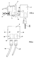
- the socket according to the invention essentially comprises a faceplate 1, a connector 2, a printed circuit board 3, provided with contacts 4, and, optionally a protective cover 5.
- the socket can be placed on supports such as a plinth, a rack, a cabinet, and depending on the case, the cover can be useful or not.
- the faceplate 1 allows attachment to the support, by means of latching notches or holes 11A, the interior of which can be furnished with a threaded metal socket.
- the front face of the faceplate has an opening 12, possibly closable by a sliding shutter, to receive the end plug 13 of a cable 14, and also advantageously includes a label holder 15.
- the rear face of the faceplate comprises means elastic snap 16 to fix the socket and possibly the various elements housed behind the front plate.
- a connector 2 is arranged behind the faceplate, opposite the opening 12, to cooperate with the plug 13 of the cable.
- This connector can for example be of the standard RJ45 type.
- An important feature of the present invention is the presence of a card 3 printed circuit board, which gives the socket numerous adaptation possibilities.
- the socket has contacts 4, on which are connected pairs 6 of communication conductors. According to a characteristic of the present invention, the contacts, which can advantageously be of the insulation displacement type, are mounted on the card 3, and the pins 21 for connecting the connector 2 can come into resilient abutment on contacts of the card, which can be the ends 41 of the contacts 4.
- the card 3 can be fixed by snap-fastening on the faceplate, and ensures the maintenance in position of the connector 2, which can also be fixed in a conventional manner.
- the cover 5 has been shown with a shape, delimiting an interior volume making it possible to receive an optical transducer 7, such as a gallium arsenide converter.
- This transducer transforms into optical signals the optical signals received by the optical cables 53.
- the transducer can be remotely supplied by one of the pairs 6. It is possible to provide a control light signal, for example an LED 17, validating the electrical supply.
- the cover is formed with an opening 51 for the outward passage of contacts 4, and one or more openings 52 for the passage each of a fiber optic cable 53.
- the cover can be fixed by snap-fastening or by means of screws passing through holes 11B aligned with holes 11A on the faceplate.
- the transducer 7 can be fixed on the card 3, which includes components for transmitting the electrical signals delivered by the transducer and for transmitting to the transducer the power received on certain contacts 4.
- the optical cable entries are placed on top. They could be in another place, for example on the back side.
- the optical and electronic inputs have been shown to be separate. It is possible to provide a single input, for a mixed cable, comprising for example four electronic pairs and two optical fibers.
- the connector 2, of the RJ45 type can have eight output pins, four of which correspond to two input pairs 6 (another pair is used for the 5V supply of the transducer, and another pair does not is not used). The other remaining pins of the connector 2 are used for the outputs of the electronic signals coming from the transducer 7 and corresponding to the optical signals.
- an electrical protocol adaptation box 8 hereinafter designated adapter is associated with the socket as described above.
- Such an assembly is shown in elevation in FIG. 3, and at the end from the right in FIG. 4.
- the adapter can be fixed to the socket by means of two screws 81, 82 screwed into the holes 11A of the faceplate 1 of the socket against which the faceplate is applied.
- the adapter is provided with a plug 83 which is intended to be inserted through the opening 12 of the faceplate, into the connector of the socket.
- the adapter can be supplied with 5V by the two screws 81, 82.
- the adapter advantageously includes an LED 84 for enabling the supply.
- a connector 91 for the transmission of electronic data signals for the direct connection of an item of equipment on a network carried by the pairs, receiving a cable two pairs 92, and at least one connector 93, receiving a two pair cable 94 for the indirect connection of equipment to the adapter via optical fibers.
- the network carried by the pairs only crosses the adapter, while the optoelectric signals are formatted to a protocol by the adapter.
- the socket is thus trivialized because it can support any application due to the adapter, provided and designed according to the protocol or specific need of the network.
Landscapes
- Physics & Mathematics (AREA)
- General Physics & Mathematics (AREA)
- Optics & Photonics (AREA)
- Optical Couplings Of Light Guides (AREA)
- Connector Housings Or Holding Contact Members (AREA)
Applications Claiming Priority (2)
| Application Number | Priority Date | Filing Date | Title |
|---|---|---|---|
| FR9404532A FR2718893B1 (fr) | 1994-04-15 | 1994-04-15 | Prise adaptable pour précâblage banalisé, pour système de communication. |
| FR9404532 | 1994-04-15 |
Publications (1)
| Publication Number | Publication Date |
|---|---|
| EP0677757A1 true EP0677757A1 (fr) | 1995-10-18 |
Family
ID=9462157
Family Applications (1)
| Application Number | Title | Priority Date | Filing Date |
|---|---|---|---|
| EP95400786A Withdrawn EP0677757A1 (fr) | 1994-04-15 | 1995-04-07 | Prise adaptable pour précâblage banalisé, pour système de communication |
Country Status (3)
| Country | Link |
|---|---|
| EP (1) | EP0677757A1 (ja) |
| JP (1) | JPH0886941A (ja) |
| FR (1) | FR2718893B1 (ja) |
Cited By (9)
| Publication number | Priority date | Publication date | Assignee | Title |
|---|---|---|---|---|
| DE29618489U1 (de) * | 1996-10-23 | 1997-08-21 | Oels, Wolf-Dieter, Dr.-Ing., 44229 Dortmund | Vorrichtung zur Umsetzung und/oder Übertragung von optischen und/oder elektrischen Signalen |
| FR2762100A1 (fr) * | 1997-04-15 | 1998-10-16 | Infra Sa | Prise opto-electrique et ensemble de connexion opto-electrique pour le precablage de batiment |
| WO1999042877A1 (de) * | 1998-02-17 | 1999-08-26 | Reichle + De Massari Ag Elektro-Ingenieure | Kontaktsteckeranordnung für lichtwellenleiter |
| WO2002013333A3 (en) * | 2000-08-10 | 2002-05-02 | Adc Telecommunications Inc | Upgradeable media wall converter and housing |
| WO2002061481A3 (en) * | 2000-10-31 | 2003-03-27 | Viasystems Group Inc | Fiber optic circuit board connector |
| EP1310813A1 (de) * | 2001-11-08 | 2003-05-14 | DaimlerChrysler AG | Stecker und Steckeraufnahme für ein optoelektronisches Steckersystem |
| WO2004010755A1 (en) * | 2002-07-18 | 2004-01-29 | Adc Telecommunication, Inc. | Media wall converter and housing |
| US7178994B2 (en) | 2000-10-31 | 2007-02-20 | Viasystems Group, Inc. | Fiber optic circuit connector |
| WO2010125548A1 (en) * | 2009-04-28 | 2010-11-04 | Firecomms Limited | A connector |
Families Citing this family (2)
| Publication number | Priority date | Publication date | Assignee | Title |
|---|---|---|---|---|
| SE517647C2 (sv) * | 2000-04-17 | 2002-07-02 | Transmode Systems Ab | Kontaktanordning och användning av densamma |
| JP5214308B2 (ja) * | 2008-04-11 | 2013-06-19 | Dxアンテナ株式会社 | 光受信機 |
Citations (6)
| Publication number | Priority date | Publication date | Assignee | Title |
|---|---|---|---|---|
| US4444451A (en) * | 1982-03-05 | 1984-04-24 | Amp Incorporated | Modular plug-dual modular jack adaptor |
| WO1988002190A1 (en) * | 1986-09-22 | 1988-03-24 | American Telephone & Telegraph Company | Connector assembly |
| EP0456298A1 (en) * | 1990-04-23 | 1991-11-13 | E.I. Du Pont De Nemours And Company | A device for electro-optical signal conversion |
| EP0484243A1 (fr) * | 1990-10-31 | 1992-05-06 | Jacques E. Nozick | Prise courants faibles pour précâblage de bâtiment |
| EP0498342A2 (de) * | 1991-02-08 | 1992-08-12 | Siemens Aktiengesellschaft | Anschlusseinrichtung unter Verwendung einer Steckdose |
| EP0538982A2 (en) * | 1991-10-24 | 1993-04-28 | Intel Corporation | Integral connector system for credit card size I/O card external connector |
-
1994
- 1994-04-15 FR FR9404532A patent/FR2718893B1/fr not_active Expired - Fee Related
-
1995
- 1995-04-07 EP EP95400786A patent/EP0677757A1/fr not_active Withdrawn
- 1995-04-13 JP JP7111042A patent/JPH0886941A/ja not_active Withdrawn
Patent Citations (6)
| Publication number | Priority date | Publication date | Assignee | Title |
|---|---|---|---|---|
| US4444451A (en) * | 1982-03-05 | 1984-04-24 | Amp Incorporated | Modular plug-dual modular jack adaptor |
| WO1988002190A1 (en) * | 1986-09-22 | 1988-03-24 | American Telephone & Telegraph Company | Connector assembly |
| EP0456298A1 (en) * | 1990-04-23 | 1991-11-13 | E.I. Du Pont De Nemours And Company | A device for electro-optical signal conversion |
| EP0484243A1 (fr) * | 1990-10-31 | 1992-05-06 | Jacques E. Nozick | Prise courants faibles pour précâblage de bâtiment |
| EP0498342A2 (de) * | 1991-02-08 | 1992-08-12 | Siemens Aktiengesellschaft | Anschlusseinrichtung unter Verwendung einer Steckdose |
| EP0538982A2 (en) * | 1991-10-24 | 1993-04-28 | Intel Corporation | Integral connector system for credit card size I/O card external connector |
Cited By (15)
| Publication number | Priority date | Publication date | Assignee | Title |
|---|---|---|---|---|
| DE29618489U1 (de) * | 1996-10-23 | 1997-08-21 | Oels, Wolf-Dieter, Dr.-Ing., 44229 Dortmund | Vorrichtung zur Umsetzung und/oder Übertragung von optischen und/oder elektrischen Signalen |
| FR2762100A1 (fr) * | 1997-04-15 | 1998-10-16 | Infra Sa | Prise opto-electrique et ensemble de connexion opto-electrique pour le precablage de batiment |
| WO1998047031A1 (fr) * | 1997-04-15 | 1998-10-22 | Infra + | Prise opto-electrique et ensemble de connexion opto-electrique pour le precablage de batiment |
| WO1999042877A1 (de) * | 1998-02-17 | 1999-08-26 | Reichle + De Massari Ag Elektro-Ingenieure | Kontaktsteckeranordnung für lichtwellenleiter |
| US6318904B1 (en) | 1998-02-17 | 2001-11-20 | Reichle & De-Massari Ag | Contact connector system for light waveguides |
| WO2002013333A3 (en) * | 2000-08-10 | 2002-05-02 | Adc Telecommunications Inc | Upgradeable media wall converter and housing |
| WO2002061481A3 (en) * | 2000-10-31 | 2003-03-27 | Viasystems Group Inc | Fiber optic circuit board connector |
| US6848840B2 (en) | 2000-10-31 | 2005-02-01 | Viasystems Group, Inc. | Fiber optic circuit board connector |
| US6976793B2 (en) | 2000-10-31 | 2005-12-20 | Viasystems Group, Inc. | Fiber optic circuit connector |
| AU2002248276B2 (en) * | 2000-10-31 | 2006-07-06 | Viasystems Group, Inc. | Fiber optic circuit board connector |
| US7178994B2 (en) | 2000-10-31 | 2007-02-20 | Viasystems Group, Inc. | Fiber optic circuit connector |
| EP1310813A1 (de) * | 2001-11-08 | 2003-05-14 | DaimlerChrysler AG | Stecker und Steckeraufnahme für ein optoelektronisches Steckersystem |
| WO2004010755A1 (en) * | 2002-07-18 | 2004-01-29 | Adc Telecommunication, Inc. | Media wall converter and housing |
| US6854895B2 (en) | 2002-07-18 | 2005-02-15 | Adc Telecommunications, Inc. | Media wall converter and housing |
| WO2010125548A1 (en) * | 2009-04-28 | 2010-11-04 | Firecomms Limited | A connector |
Also Published As
| Publication number | Publication date |
|---|---|
| FR2718893B1 (fr) | 1996-07-12 |
| FR2718893A1 (fr) | 1995-10-20 |
| JPH0886941A (ja) | 1996-04-02 |
Similar Documents
| Publication | Publication Date | Title |
|---|---|---|
| CA2251995C (fr) | Dispositif d'interface entre equipements d'une installation | |
| US7490996B2 (en) | Electro-optical plug and receptacle | |
| KR100448951B1 (ko) | 광 섬유 커넥터 모듈 | |
| US7970251B2 (en) | Outlet device | |
| US20040013369A1 (en) | Media wall converter and housing | |
| CN101449190A (zh) | 用于无线接入的光纤缆线和光纤缆线组件 | |
| FR2512612A1 (fr) | Systeme de distribution pour reseau de fibres local | |
| EP0677757A1 (fr) | Prise adaptable pour précâblage banalisé, pour système de communication | |
| US8229266B2 (en) | Optical signal distribution assembly with optical connector holder | |
| CN105453458A (zh) | 波分复用器模块 | |
| CN112005530A (zh) | 可热插拔的无线缆接触交换机壳体 | |
| NL1026832C2 (nl) | Inrichting voor het aansluiten van apparaten op lichtgeleidende vezels. | |
| CN102428396B (zh) | 分光器组件 | |
| US5176534A (en) | Low-current receptacle for prewiring a building | |
| CN116097145B (zh) | 光电模块、光电插接连接器以及光电子分配器 | |
| US6418195B1 (en) | Apparatus for communicating a diagnostic device with a telecommunications system through a remote network unit | |
| WO1998047031A1 (fr) | Prise opto-electrique et ensemble de connexion opto-electrique pour le precablage de batiment | |
| JP2004191883A (ja) | 光情報コンセント | |
| US7150656B1 (en) | Digital switching cross-connect module | |
| GB2299459A (en) | Modular electronic or optical assembly | |
| HK1165014B (en) | Splitter module | |
| FR2858059A1 (fr) | Module de raccordement pour chaine de securite | |
| FR2866157A1 (fr) | Interface passive de reseau, boitier individuel comprenant une telle interface passive et dispositif electronique comprenant une telle interface passive | |
| GB2494375A (en) | Breakout connection box |
Legal Events
| Date | Code | Title | Description |
|---|---|---|---|
| PUAI | Public reference made under article 153(3) epc to a published international application that has entered the european phase |
Free format text: ORIGINAL CODE: 0009012 |
|
| AK | Designated contracting states |
Kind code of ref document: A1 Designated state(s): DE ES FR GB IT |
|
| 17P | Request for examination filed |
Effective date: 19960329 |
|
| 17Q | First examination report despatched |
Effective date: 19990415 |
|
| STAA | Information on the status of an ep patent application or granted ep patent |
Free format text: STATUS: THE APPLICATION IS DEEMED TO BE WITHDRAWN |
|
| 18D | Application deemed to be withdrawn |
Effective date: 19991026 |