EP0677760A2 - Linsenkontrollvorrichtung - Google Patents
Linsenkontrollvorrichtung Download PDFInfo
- Publication number
- EP0677760A2 EP0677760A2 EP95302346A EP95302346A EP0677760A2 EP 0677760 A2 EP0677760 A2 EP 0677760A2 EP 95302346 A EP95302346 A EP 95302346A EP 95302346 A EP95302346 A EP 95302346A EP 0677760 A2 EP0677760 A2 EP 0677760A2
- Authority
- EP
- European Patent Office
- Prior art keywords
- lens
- area
- variator
- wide
- compensation
- Prior art date
- Legal status (The legal status is an assumption and is not a legal conclusion. Google has not performed a legal analysis and makes no representation as to the accuracy of the status listed.)
- Granted
Links
- 238000006243 chemical reaction Methods 0.000 claims abstract description 42
- 230000003287 optical effect Effects 0.000 claims abstract description 36
- 230000004044 response Effects 0.000 claims abstract description 17
- 230000008859 change Effects 0.000 claims description 11
- 238000006073 displacement reaction Methods 0.000 abstract description 3
- 238000012937 correction Methods 0.000 abstract description 2
- 238000012545 processing Methods 0.000 description 62
- 238000010586 diagram Methods 0.000 description 32
- 238000004364 calculation method Methods 0.000 description 30
- 238000000034 method Methods 0.000 description 24
- 230000008569 process Effects 0.000 description 11
- 238000011156 evaluation Methods 0.000 description 8
- 238000010276 construction Methods 0.000 description 7
- 230000006870 function Effects 0.000 description 6
- 230000007704 transition Effects 0.000 description 6
- 230000005540 biological transmission Effects 0.000 description 4
- 238000001514 detection method Methods 0.000 description 4
- 238000003384 imaging method Methods 0.000 description 4
- 238000004891 communication Methods 0.000 description 3
- 238000005259 measurement Methods 0.000 description 3
- 238000013461 design Methods 0.000 description 2
- 230000000694 effects Effects 0.000 description 2
- 230000002457 bidirectional effect Effects 0.000 description 1
- 230000002542 deteriorative effect Effects 0.000 description 1
- 239000000284 extract Substances 0.000 description 1
- 239000004973 liquid crystal related substance Substances 0.000 description 1
- 230000007246 mechanism Effects 0.000 description 1
Images










Classifications
-
- G—PHYSICS
- G02—OPTICS
- G02B—OPTICAL ELEMENTS, SYSTEMS OR APPARATUS
- G02B7/00—Mountings, adjusting means, or light-tight connections, for optical elements
- G02B7/02—Mountings, adjusting means, or light-tight connections, for optical elements for lenses
- G02B7/04—Mountings, adjusting means, or light-tight connections, for optical elements for lenses with mechanism for focusing or varying magnification
- G02B7/10—Mountings, adjusting means, or light-tight connections, for optical elements for lenses with mechanism for focusing or varying magnification by relative axial movement of several lenses, e.g. of varifocal objective lens
- G02B7/102—Mountings, adjusting means, or light-tight connections, for optical elements for lenses with mechanism for focusing or varying magnification by relative axial movement of several lenses, e.g. of varifocal objective lens controlled by a microcomputer
-
- G—PHYSICS
- G03—PHOTOGRAPHY; CINEMATOGRAPHY; ANALOGOUS TECHNIQUES USING WAVES OTHER THAN OPTICAL WAVES; ELECTROGRAPHY; HOLOGRAPHY
- G03B—APPARATUS OR ARRANGEMENTS FOR TAKING PHOTOGRAPHS OR FOR PROJECTING OR VIEWING THEM; APPARATUS OR ARRANGEMENTS EMPLOYING ANALOGOUS TECHNIQUES USING WAVES OTHER THAN OPTICAL WAVES; ACCESSORIES THEREFOR
- G03B17/00—Details of cameras or camera bodies; Accessories therefor
- G03B17/56—Accessories
- G03B17/565—Optical accessories, e.g. converters for close-up photography, tele-convertors, wide-angle convertors
-
- H—ELECTRICITY
- H04—ELECTRIC COMMUNICATION TECHNIQUE
- H04N—PICTORIAL COMMUNICATION, e.g. TELEVISION
- H04N23/00—Cameras or camera modules comprising electronic image sensors; Control thereof
- H04N23/50—Constructional details
- H04N23/55—Optical parts specially adapted for electronic image sensors; Mounting thereof
-
- H—ELECTRICITY
- H04—ELECTRIC COMMUNICATION TECHNIQUE
- H04N—PICTORIAL COMMUNICATION, e.g. TELEVISION
- H04N23/00—Cameras or camera modules comprising electronic image sensors; Control thereof
- H04N23/60—Control of cameras or camera modules
- H04N23/66—Remote control of cameras or camera parts, e.g. by remote control devices
- H04N23/663—Remote control of cameras or camera parts, e.g. by remote control devices for controlling interchangeable camera parts based on electronic image sensor signals
-
- H—ELECTRICITY
- H04—ELECTRIC COMMUNICATION TECHNIQUE
- H04N—PICTORIAL COMMUNICATION, e.g. TELEVISION
- H04N23/00—Cameras or camera modules comprising electronic image sensors; Control thereof
- H04N23/60—Control of cameras or camera modules
- H04N23/69—Control of means for changing angle of the field of view, e.g. optical zoom objectives or electronic zooming
-
- G—PHYSICS
- G02—OPTICS
- G02B—OPTICAL ELEMENTS, SYSTEMS OR APPARATUS
- G02B15/00—Optical objectives with means for varying the magnification
- G02B15/02—Optical objectives with means for varying the magnification by changing, adding, or subtracting a part of the objective, e.g. convertible objective
- G02B15/10—Optical objectives with means for varying the magnification by changing, adding, or subtracting a part of the objective, e.g. convertible objective by adding a part, e.g. close-up attachment
-
- H—ELECTRICITY
- H04—ELECTRIC COMMUNICATION TECHNIQUE
- H04N—PICTORIAL COMMUNICATION, e.g. TELEVISION
- H04N23/00—Cameras or camera modules comprising electronic image sensors; Control thereof
- H04N23/60—Control of cameras or camera modules
- H04N23/67—Focus control based on electronic image sensor signals
- H04N23/673—Focus control based on electronic image sensor signals based on contrast or high frequency components of image signals, e.g. hill climbing method
Definitions
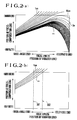
- the position of the focus-compensation lens 105 that results in an optical image on the imaging surface of the CCD 106, namely, the focused position of the focus-compensation lens 105 varies with the distance to the object as shown in Fig. 2(a).
- the focused position of the focus-compensation lens 105 varies with the focal length of the zoom lens unit 100, namely, the position of the variator lens 102.
- an optical image is obtained through the light which is focused by shifting the focus-compensation lens 105 according to the curve resulting from the focal length set and the object distance.
- the zoom lens unit suffers from a noticeably unfocused state until the variator lens 102 reaches the fixed position, and thereafter the zoom lens unit takes a substantially long time to reach a focused position from the arrival of the variator lens 102 at the fixed position.
- the variator lens 102 is forced to move closer to the wide-angle side when power is switched on with the wide-angle attachment lens 121 mounted onto the zoom lens unit 100.
- an unfocused image output and varied field of view result during the forced movement of the variator lens 102. If the mounting of the wide-angle attachment lens 121 goes unnoticed, these may be confusing to an operator.
- a lens control device or a camera comprises a zoom lens unit having a variator lens group and a compensation lens group which compensates for in a focused position a variation arising from power variation operation of the variator lens group, a conversion lens group which is mounted in an optical axis of the zoom lens unit in a detachable manner, and which shifts a focusable focal length area of the zoom lens unit to a second focal length area from a first focal length area while the conversion lens group is mounted, position detecting means for detecting a position of the compensation lens group on the basis of a predetermined reference position, and reference position shifting means for shifting the predetermined reference position to a reference position corresponding to the second focal length area when the conversion lens group is mounted on the zoom lens unit.
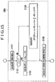
- Fig. 15 is a flow diagram showing the follow processing routine of Fig. 13.
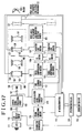
- An image pickup device 106 such as a CCD is arranged behind the zoom lens unit 100, namely, behind the focus-compensation lens 105.
- An imaging surface that bears an optical image of an object is provided on one side of the CCD 106 facing the focus-compensation lens 105.
- the AF evaluation signal generated by the AF evaluation value processing circuit 114 is sent to an AF control microcomputer (hereinafter referred to as AF microcomputer) 115.
- the AF microcomputer 115 has the general control over the lens driving.
- the AF microcomputer 115 receives a detection signal from a wide-angle attachment lens mounting detecting switch 123. In response to the detection signal and the AF evaluation signal, the AF microcomputer 115 generates the control signal for shifting the variator lens 102, the control signal for shifting the focus-compensation lens 105, and a command signal instructing a change of distance measurement frame.
- the zoom processing routine is followed by a driving direction and speed selecting routine (step S206).
- driving direction and speed are selected from driving direction and speed of the variator lens 102 and driving direction and speed of the focus-compensation lens 105, determined in steps S203 and S204.
- Each of the variator lens and the focus-compensation lens has its own range of travel terminated with both mechanical ends. Provided in the vicinity of each mechanical end is an electrical end or software end.
- 9(a) and 9(b) are tables, each listing representative values representing the relationship between the focal length (the position of the variator lens) of the zoom lens unit and the position of the focus-compensation lens with no wide-angle attachment lens mounted and the same relationship but with the wide-angle attachment lens mounted in Fig.5.
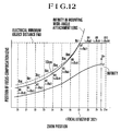
- the degree of unfocusing is minimized by allowing the focus-compensation lens to follow the 10 cm cam locus f2 with no wide-angle attachment lens mounted, which is most closely positioned to the locus of infinity object distance with the wide-angle attachment lens mounted, in the course of movement of the variator lens into within the focusable focal length area.
- a9-px is the driving distance of the focus-compensation lens 105.
- ⁇ Z the position difference between two neighboring positions of zx to z9 of the variator lens 102
- Zsp the speed (zoom speed) of the variator lens 102.
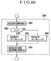
- the focus following speed (the speed of the focus-compensation lens) Fsp is determined by Equation (4).
- Fsp ⁇ F * Zsp /
- a9 and z9 are corresponding values in the wide-angle side on the tables nearest to the current position.
- the driving operation of the focus-compensation lens 105 performed on the basis of the focus driving direction and the focus driving speed is discussed in detail.
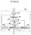
- the zoom area variable v is initialized by resetting it to "0".
- the zoom positions Z(v) at boundaries between zoom areas are calculated (step S702).
- the zoom positions Z(v) correspond to z0, z1, z2,... in Fig. 12.
- Z(v) (Telephoto end zoom position - Wide-angle end zoom position) * v/s + Wide-angle end zoom position
- step S602 reveals that the current position of the variator lens lies in the telephoto side of 302
- a target position to be followed is set to data A(h,v-1) in the zoom area, v-1, which is shifted to the wide-angle side by one zoom area from the current position of the variator lens, and a difference quantity ⁇ F between A(h,v-1) and the current position Px of the focus-compensation lens is then calculated (step S603).
- the following equation (6) determines the difference ⁇ F.
- step S901 When the wide-angle attachment lens is not mounted (step S901), the preparation end flag fg is set to "0" (step S907), and calculation routine for cam locus parameters, ⁇ , ⁇ , and ⁇ is executed (step S909).
- the calculation routine for cam locus parameters, ⁇ , ⁇ , and ⁇ is further discussed in detail later.
- step S1002 object distance n is initialized to "0" (step S1002).
- step S1003 When the boundary flag is "1" in step S1003, the object distance n, focused position of the focus-compensation lens 105 A(n,v), A(n+1,v) relative to the variator lens 102 are read, and A(n,v) and A(n+1,v) are stored as ax and bx (step S1007).
- the current position of the variator lens 102 is to the telephoto side of the position 302 in Fig. 2(b) (corresponding to Z7 in Fig.16).
- the difference ⁇ F is determined from the above Equation (6) (step S1103).
- A(h,v-1) is used to as the target position to be followed.
- Px represents the current position of the focus-compensation lens 105.
- the forced zoom operation into the focusable focal length area is performed without creating unfocused state regardless of the object distance that was used immediately before the mounting of the wide-angle attachment lens. Also, the forced zoom operation is performed while keeping an object in focus even if the slope of the locus of object distance greatly varies with object distance as a result of mounting the wide-angle attachment lens 121.
- the variator lens group is forced to move to a predetermined position within a second focal length area when the conversion lens group is mounted.
- the focused position of the focus-compensation lens group relative to the variator lens group, varying with the forced shifting of the variator lens group, is calculated.
- the focus-compensation lens group is then so shifted so that it follows the calculated focused position.
- the forced zoom operation is thus performed while keeping an object in focus with the conversion lens group such as the wide-angle attachment lens mounted. Furthermore, an improved automatic focus adjustment response results.
- a position counter to detect an instantaneous position of the variator lens 102 and a position counter to detect an instantaneous position of the focus-compensation lens 105. If the counts of the position counters suffer from a deviation or an error, retrieval of the locus data stored in the AF microcomputer also suffers from an error, wherein the locus data are a combination of coordinates consisting of the position of the variator lens 102 and the position of the focus-compensation lens 105. Such an incorrect data retrieval leads to an incorrect follow operation for keeping the focused state. A power variation operation thus creates an unfocused state.
- the focal length exceeds a limit 301, the curves representing the relationship, in terms of object distance as parameters, between the focal length and the position of the focus-compensation lens 105 diverge out of the focusable focal length area. If the focal length is kept to within the limit 301, namely, the focal length is set to any value closer to the wide-angle side, focus adjustment by means of the focus-compensation lens 105 remains workable. If the focal length exceeds the limit 301, however, namely, the focal length is set to any value closer to the telephoto side, focus adjustment by means of the focus-compensation lens 105 is impossible.
- the variator lens 102 is moved until the focal length is set to be closer to the wide-angle side, and is fixed there. Therefore, the variator lens 102 is fixed at such a predetermined position, and zooming operation is disabled when the wide-angle attachment lens 121 is mounted.
- the variator lens 102 is forced to move closer to the wide-angle side when power is switched on with the wide-angle attachment lens 121 mounted onto the zoom lens unit 100.
- an unfocused image output and varied field of view result during the forced movement of the variator lens 102. If the mounting of the wide-angle attachment lens 121 goes unnoticed, these may be confusing to an operator.
- the focus-compensation lens 105 contains a photosensor 130 for detecting whether the focus-compensation lens 105 is situated at its reference position or not.
- the optical path of the photosensor 130 is opened or closed by a position detecting switch 129.
- the position detectingr switch 129 is attached onto the lens casing.
- the position detecting switch 129 is mounted with its boundary, between block and transmission of light, coming to the middle of the range of travel of the focus-compensation lens 105.
- the movement of the photosensor 130 relative to the position detecting switch 129 allows the output light to be blocked or transmitted.
- the signal responsive to the output light transitions from H to L level. The point of this signal transition is identified as the reference position.
- a determination is made of whether the focus-compensation lens 105 is positioned at the reference position or not.
- the photosensor 128 comprises an emitter element 401 for emitting light and a photosensor element 402 which faces the emitter element 401.
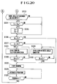
- a determination is made of whether power is switched on or not (step S1301). When power is not switched on, a wait state is kept. When power is switched on, a count Cz at a zoom lens position counter is cleared (step S1302), and a determination is made of whether the output signal of the photosensor 128 is at an H level or not (step S1303). For example, when the boundary between block and transmission of light is at the middle of the range of travel of the variator lens 102, the output signal level of the photosensor 128 identifies whether the boundary is on the telephoto side or on the wide-angle side relative to the current variator lens position. In Fig.
- the count Cz is once stored as C0 into a memory (step S1310).
- the count Cz indicates, immediately after power on, the value of stepping pulses of the variator lens motor 118 between the position of the variator lens 102 prior to the reset operation and the position detecting switch 127, and this value represents the distance between the position of the variator lens 102 prior to power on and the position of the position detecting switch 127.
- step S1314 a determination is made of whether C0 is within the focusable focal length area with the wide-angle attachment lens mounted, based on the determination of whether the absolute lens position C0 stored in the memory is greater than Cwa or not (step S1314).
- Cwa corresponds to the focal length, the position 301 of the variator lens 102 in Fig. 2(b).
- step S1314 When C0 is greater than Cwa at step S1314, return position C0 with the wide-angle attachment lens 102 mounted is positioned to the telephoto side relative to Cwa. Thus, no focused position is found by returning the variator lens 102 back to C0.
- the return position C0 is once stored as C2 (this C2 is to be used in the following fifth embodiment), and C0 is set to a position C1 to the wide-angle side relative to Cwa (step S1315).
- C1 is acceptable as long as it is to the wide-angle side relative to Cwa.
- the position C1 is preferably situated at the zoom position at the wide-angle end where the performance of the wide-angle attachment lens 121 is fully exploited.
- the variator lens 102 is moved to the wide-angle side based on the determination that the return direction is to the wide-angle side (step S1320).
- step S1325 a determination is made of whether power is interrupted or not (step S1325).
- the program returns to step S1301.
- step S1325 the ordinary operation is continued.
- FIGs. 21 and 22 are flow diagrams showing the reset operation at the manual mode startup in the camera according to the fifth embodiment of the present invention with the wide-angle attachment lens mounted.
- the circuit configuration of the camera in the fifth embodiment remains unchanged from that in Fig. 17.
- This embodiment differs from the previous embodiments in the process algorithm of the AF microcomputer 115.
- the reset operation of the focus-compensation lens position counter is controlled by the AF microcomputer 115.
- step S1504 When the output signal level of the photosensor 130 is at an L level (step S1504), the focus-compensation lens 105 is moved toward the infinity side to acquire the boundary point (step S1508).
- the count Cf is decremented by -1 in synchronism with the stepping pulse of the focus-compensation lens motor 120 (step S1510).
- step S1510 a determination is made of whether the output signal level of the photosensor 130 is at an H level or not.
- the process starts over with step S1508.
- step S1520 a determination is made of whether the return position Cf0 is equal to or smaller than Cf (step S1520).
- the return position Cf0 is equal to or greater than Cf
- the movement of the focus-compensation lens 105 is stopped (step S1523) based on the determination that the focus-compensation lens 105 has already arrived at the return position Cf0.
- the return position Cf0 is greater than Cf
- the process starts over with step S1519.
- the focus-compensation lens 105 is moved to the infinity side based on the determination that the return direction of the focus-compensation lens 105 is to the infinity side (step S1521).
- step S1514 In succession to the stop of movement of the focus-compensation lens 105, the ordinary operation of the camera takes place (step S1514). In the ordinary operation, a photographed image is output in the ordinary photographing activity.
- step S1525 a determination is made of whether power is interrupted or not (step S1525). When power is interrupted, the program returns to step S1501. When power is not interrupted, the ordinary operation is continued.
- initialization of the position detecting means is performed by shifting the compensation lens group to the reference position.
- the error in position sensing by the position detecting means is controlled.
Landscapes
- Engineering & Computer Science (AREA)
- Multimedia (AREA)
- Signal Processing (AREA)
- Physics & Mathematics (AREA)
- General Physics & Mathematics (AREA)
- General Engineering & Computer Science (AREA)
- Optics & Photonics (AREA)
- Lens Barrels (AREA)
- Structure And Mechanism Of Cameras (AREA)
Applications Claiming Priority (6)
| Application Number | Priority Date | Filing Date | Title |
|---|---|---|---|
| JP98029/94 | 1994-04-12 | ||
| JP9802994A JPH07281072A (ja) | 1994-04-12 | 1994-04-12 | カメラ |
| JP9802894 | 1994-04-12 | ||
| JP9802994 | 1994-04-12 | ||
| JP09802894A JP3466700B2 (ja) | 1994-04-12 | 1994-04-12 | カメラ |
| JP98028/94 | 1994-04-12 |
Publications (3)
| Publication Number | Publication Date |
|---|---|
| EP0677760A2 true EP0677760A2 (de) | 1995-10-18 |
| EP0677760A3 EP0677760A3 (de) | 1996-01-17 |
| EP0677760B1 EP0677760B1 (de) | 2000-10-11 |
Family
ID=26439202
Family Applications (1)
| Application Number | Title | Priority Date | Filing Date |
|---|---|---|---|
| EP95302346A Expired - Lifetime EP0677760B1 (de) | 1994-04-12 | 1995-04-10 | Linsenkontrollvorrichtung |
Country Status (6)
| Country | Link |
|---|---|
| US (1) | US6744468B2 (de) |
| EP (1) | EP0677760B1 (de) |
| KR (1) | KR0173159B1 (de) |
| CN (1) | CN1114126C (de) |
| DE (1) | DE69519050T2 (de) |
| SG (2) | SG102527A1 (de) |
Cited By (2)
| Publication number | Priority date | Publication date | Assignee | Title |
|---|---|---|---|---|
| EP1638318A3 (de) * | 1995-08-29 | 2007-10-03 | Canon Kabushiki Kaisha | Videokamera mit auswechselbarer Linsenvorrichtung |
| US7616876B2 (en) * | 2003-10-14 | 2009-11-10 | Canon Kabushiki Kaisha | Imaging device |
Families Citing this family (17)
| Publication number | Priority date | Publication date | Assignee | Title |
|---|---|---|---|---|
| US6989865B1 (en) * | 1997-12-19 | 2006-01-24 | Canon Kabushiki Kaisha | Optical equipment and it control method, and computer-readable storage medium |
| JP3530906B2 (ja) * | 2001-03-30 | 2004-05-24 | ミノルタ株式会社 | 結像位置検出プログラムおよびカメラ |
| KR20040062247A (ko) * | 2003-01-02 | 2004-07-07 | 엘지전자 주식회사 | 홍채 인식 카메라의 구조 및 그 사용 방법 |
| JP4478419B2 (ja) * | 2003-09-02 | 2010-06-09 | キヤノン株式会社 | レンズ制御装置、光学機器およびレンズ制御方法 |
| JP4551708B2 (ja) * | 2004-07-21 | 2010-09-29 | キヤノン株式会社 | 撮像装置 |
| JP2008058399A (ja) * | 2006-08-29 | 2008-03-13 | Canon Inc | 焦点調節装置、撮像装置、および制御方法 |
| KR100880672B1 (ko) * | 2007-07-18 | 2009-02-02 | 자화전자 주식회사 | 자동초점 기능을 구비한 카메라 시스템 및 그 제어방법 |
| JP5574729B2 (ja) * | 2010-02-03 | 2014-08-20 | キヤノン株式会社 | レンズ制御装置、その制御方法及びプログラム |
| JP5590903B2 (ja) * | 2010-02-05 | 2014-09-17 | キヤノン株式会社 | 撮像レンズ、撮像装置、及び撮像装置の制御方法 |
| JP5750694B2 (ja) * | 2011-03-25 | 2015-07-22 | オリンパス株式会社 | 交換レンズ |
| KR101293245B1 (ko) * | 2012-02-21 | 2013-08-09 | (주)비에이치비씨 | 광학 줌 카메라의 줌 트래킹 자동 초점 제어기 및 그 제어 방법 |
| JP6003199B2 (ja) * | 2012-05-08 | 2016-10-05 | ソニー株式会社 | レンズ交換式カメラシステムおよびレンズデータ取得プログラム |
| JP2016006480A (ja) * | 2014-05-27 | 2016-01-14 | パナソニックIpマネジメント株式会社 | 撮像装置 |
| EP3955057B1 (de) * | 2017-05-31 | 2023-05-10 | Canon Kabushiki Kaisha | Bildgebungsvorrichtung, zwischenzubehör und steuerungsverfahren dafür |
| CN113777738A (zh) * | 2020-06-08 | 2021-12-10 | 华为技术有限公司 | 变焦镜组、镜头组件、摄像装置、电子设备及变焦方法 |
| CN113900211B (zh) * | 2020-06-18 | 2023-05-05 | 华为技术有限公司 | 自动聚焦组件、摄像装置、电子设备和自动聚焦方法 |
| CN115079369B (zh) * | 2022-05-25 | 2023-12-26 | 北京都视科技有限公司 | 镜头模组的光学对焦方法、装置、存储介质以及镜头模组 |
Family Cites Families (17)
| Publication number | Priority date | Publication date | Assignee | Title |
|---|---|---|---|---|
| JPH0654366B2 (ja) * | 1985-05-20 | 1994-07-20 | ウエスト電気株式会社 | ズ−ミング方法およびズ−ミング装置 |
| US4994842A (en) * | 1987-02-06 | 1991-02-19 | Minolta Camera Kabushiki Kaisha | Camera having a converter-attachable zoom lens |
| JP2776482B2 (ja) * | 1988-08-23 | 1998-07-16 | 株式会社リコー | レンズ制御装置 |
| US5144491A (en) | 1989-04-24 | 1992-09-01 | Canon Kabushiki Kaisha | Apparatus with lens control device |
| US5122880A (en) * | 1989-05-29 | 1992-06-16 | Canon Kabushiki Kaisha | Electronic still camera with lessened power consumption |
| JP2728943B2 (ja) | 1989-07-08 | 1998-03-18 | キヤノン株式会社 | レンズ制御装置 |
| JPH0348212A (ja) | 1989-07-17 | 1991-03-01 | Fuji Photo Film Co Ltd | ズームレンズ装置 |
| US5323200A (en) * | 1991-05-22 | 1994-06-21 | Canon Kabushiki Kaisha | Optical apparatus having lens control device |
| US5638217A (en) * | 1991-08-20 | 1997-06-10 | Canon Kabushiki Kaisha | Lens control device |
| JPH05145817A (ja) * | 1991-11-21 | 1993-06-11 | Canon Inc | ビデオカメラ |
| JPH05145819A (ja) * | 1991-11-21 | 1993-06-11 | Canon Inc | ビデオカメラ |
| US5296970A (en) | 1992-03-30 | 1994-03-22 | Fuji Photo Optical Co., Ltd | Zoom lens system |
| DE69326106T2 (de) * | 1992-06-29 | 2000-01-05 | Canon K.K., Tokio/Tokyo | Objektivkontrollgerät |
| US5790902A (en) * | 1993-09-02 | 1998-08-04 | Canon Kabushiki Kaisha | Zoom lens |
| KR950023062A (ko) * | 1993-12-21 | 1995-07-28 | 이헌조 | 비디오 카메라의 플랜지백 조정방법 |
| US5786853A (en) * | 1994-04-12 | 1998-07-28 | Canon Kabushiki Kaisha | Lens control device |
| JP3610167B2 (ja) * | 1996-07-30 | 2005-01-12 | キヤノン株式会社 | レンズ制御方法及び装置 |
-
1995
- 1995-04-10 SG SG9800306A patent/SG102527A1/en unknown
- 1995-04-10 EP EP95302346A patent/EP0677760B1/de not_active Expired - Lifetime
- 1995-04-10 DE DE69519050T patent/DE69519050T2/de not_active Expired - Lifetime
- 1995-04-10 SG SG9800302A patent/SG102526A1/en unknown
- 1995-04-12 KR KR1019950008462A patent/KR0173159B1/ko not_active Expired - Fee Related
- 1995-04-12 CN CN95104340A patent/CN1114126C/zh not_active Expired - Fee Related
-
1998
- 1998-01-13 US US09/006,567 patent/US6744468B2/en not_active Expired - Fee Related
Cited By (2)
| Publication number | Priority date | Publication date | Assignee | Title |
|---|---|---|---|---|
| EP1638318A3 (de) * | 1995-08-29 | 2007-10-03 | Canon Kabushiki Kaisha | Videokamera mit auswechselbarer Linsenvorrichtung |
| US7616876B2 (en) * | 2003-10-14 | 2009-11-10 | Canon Kabushiki Kaisha | Imaging device |
Also Published As
| Publication number | Publication date |
|---|---|
| KR950029833A (ko) | 1995-11-24 |
| DE69519050T2 (de) | 2001-10-25 |
| EP0677760A3 (de) | 1996-01-17 |
| SG102527A1 (en) | 2004-03-26 |
| SG102526A1 (en) | 2004-03-26 |
| US6744468B2 (en) | 2004-06-01 |
| KR0173159B1 (ko) | 1999-05-01 |
| DE69519050D1 (de) | 2000-11-16 |
| EP0677760B1 (de) | 2000-10-11 |
| CN1116726A (zh) | 1996-02-14 |
| US20020135693A1 (en) | 2002-09-26 |
| CN1114126C (zh) | 2003-07-09 |
Similar Documents
| Publication | Publication Date | Title |
|---|---|---|
| EP0677760B1 (de) | Linsenkontrollvorrichtung | |
| EP0677761B1 (de) | Linsenkontrollvorrichtung | |
| US7907189B2 (en) | Imaging apparatus having a lens device for a zooming control operation and the method of using the same | |
| US8045045B2 (en) | Image pickup apparatus, control method for the same, and program for implementing the control method | |
| US8665358B2 (en) | Apparatus for processing an image having detachable lens and a ring for setting photographing parameter values | |
| EP2339827A2 (de) | Autofokussystem | |
| EP1542455A2 (de) | Bildaufnahmevorrichtung, -system und Objektivorrichtung | |
| EP1065549B1 (de) | Optisches Gerät, Antriebseinheit zum Verstellen eines optischen Elements und photographisches System | |
| US6184932B1 (en) | Lens control apparatus | |
| JP3610176B2 (ja) | 撮像装置、その制御方法、及びレンズ制御装置 | |
| US5315340A (en) | Video camera apparatus | |
| US20050249489A1 (en) | Image pickup apparatus and power supply control method therefor | |
| JPH1164956A (ja) | レンズ装置、撮像装置及びコンピュータ読み取り可能な記録媒体 | |
| CN110719384B (zh) | 焦点调节设备、摄像设备、焦点调节方法及存储介质 | |
| US20050083428A1 (en) | Image pickup apparatus | |
| JPH11125860A (ja) | 交換レンズシステム及びカメラ及びレンズユニット及び制御方式 | |
| JPH1039192A (ja) | 撮像方法及び装置並びに記憶媒体 | |
| JPH10325918A (ja) | ズームレンズ装置 | |
| KR101417803B1 (ko) | 디지털 영상 처리장치 | |
| JPH10191140A (ja) | 撮像装置 | |
| JPH04213972A (ja) | フオ─カス調整装置 | |
| JP2004274515A (ja) | 撮像装置 | |
| JPH11252436A (ja) | 電子カメラ | |
| JPH04196685A (ja) | ビデオカメラの表示装置 | |
| JPH1138306A (ja) | 駆動装置及び光学機器 |
Legal Events
| Date | Code | Title | Description |
|---|---|---|---|
| PUAI | Public reference made under article 153(3) epc to a published international application that has entered the european phase |
Free format text: ORIGINAL CODE: 0009012 |
|
| AK | Designated contracting states |
Kind code of ref document: A2 Designated state(s): DE ES FR GB NL |
|
| PUAL | Search report despatched |
Free format text: ORIGINAL CODE: 0009013 |
|
| AK | Designated contracting states |
Kind code of ref document: A3 Designated state(s): DE ES FR GB NL |
|
| 17P | Request for examination filed |
Effective date: 19960530 |
|
| 17Q | First examination report despatched |
Effective date: 19981014 |
|
| GRAG | Despatch of communication of intention to grant |
Free format text: ORIGINAL CODE: EPIDOS AGRA |
|
| GRAG | Despatch of communication of intention to grant |
Free format text: ORIGINAL CODE: EPIDOS AGRA |
|
| GRAH | Despatch of communication of intention to grant a patent |
Free format text: ORIGINAL CODE: EPIDOS IGRA |
|
| GRAH | Despatch of communication of intention to grant a patent |
Free format text: ORIGINAL CODE: EPIDOS IGRA |
|
| GRAA | (expected) grant |
Free format text: ORIGINAL CODE: 0009210 |
|
| AK | Designated contracting states |
Kind code of ref document: B1 Designated state(s): DE ES FR GB NL |
|
| PG25 | Lapsed in a contracting state [announced via postgrant information from national office to epo] |
Ref country code: NL Free format text: LAPSE BECAUSE OF FAILURE TO SUBMIT A TRANSLATION OF THE DESCRIPTION OR TO PAY THE FEE WITHIN THE PRESCRIBED TIME-LIMIT Effective date: 20001011 Ref country code: ES Free format text: THE PATENT HAS BEEN ANNULLED BY A DECISION OF A NATIONAL AUTHORITY Effective date: 20001011 |
|
| REF | Corresponds to: |
Ref document number: 69519050 Country of ref document: DE Date of ref document: 20001116 |
|
| ET | Fr: translation filed | ||
| NLV1 | Nl: lapsed or annulled due to failure to fulfill the requirements of art. 29p and 29m of the patents act | ||
| PLBE | No opposition filed within time limit |
Free format text: ORIGINAL CODE: 0009261 |
|
| STAA | Information on the status of an ep patent application or granted ep patent |
Free format text: STATUS: NO OPPOSITION FILED WITHIN TIME LIMIT |
|
| 26N | No opposition filed | ||
| REG | Reference to a national code |
Ref country code: GB Ref legal event code: IF02 |
|
| PGFP | Annual fee paid to national office [announced via postgrant information from national office to epo] |
Ref country code: DE Payment date: 20130430 Year of fee payment: 19 Ref country code: GB Payment date: 20130418 Year of fee payment: 19 |
|
| PGFP | Annual fee paid to national office [announced via postgrant information from national office to epo] |
Ref country code: FR Payment date: 20130517 Year of fee payment: 19 |
|
| REG | Reference to a national code |
Ref country code: DE Ref legal event code: R119 Ref document number: 69519050 Country of ref document: DE |
|
| GBPC | Gb: european patent ceased through non-payment of renewal fee |
Effective date: 20140410 |
|
| REG | Reference to a national code |
Ref country code: FR Ref legal event code: ST Effective date: 20141231 |
|
| REG | Reference to a national code |
Ref country code: DE Ref legal event code: R119 Ref document number: 69519050 Country of ref document: DE Effective date: 20141101 |
|
| PG25 | Lapsed in a contracting state [announced via postgrant information from national office to epo] |
Ref country code: GB Free format text: LAPSE BECAUSE OF NON-PAYMENT OF DUE FEES Effective date: 20140410 Ref country code: DE Free format text: LAPSE BECAUSE OF NON-PAYMENT OF DUE FEES Effective date: 20141101 |
|
| PG25 | Lapsed in a contracting state [announced via postgrant information from national office to epo] |
Ref country code: FR Free format text: LAPSE BECAUSE OF NON-PAYMENT OF DUE FEES Effective date: 20140430 |