EP0677760B1 - Dispositif à contrôle de lentille - Google Patents
Dispositif à contrôle de lentille Download PDFInfo
- Publication number
- EP0677760B1 EP0677760B1 EP95302346A EP95302346A EP0677760B1 EP 0677760 B1 EP0677760 B1 EP 0677760B1 EP 95302346 A EP95302346 A EP 95302346A EP 95302346 A EP95302346 A EP 95302346A EP 0677760 B1 EP0677760 B1 EP 0677760B1
- Authority
- EP
- European Patent Office
- Prior art keywords
- lens
- wide
- focus
- region
- locus
- Prior art date
- Legal status (The legal status is an assumption and is not a legal conclusion. Google has not performed a legal analysis and makes no representation as to the accuracy of the status listed.)
- Expired - Lifetime
Links
- 230000003287 optical effect Effects 0.000 claims description 31
- 230000004044 response Effects 0.000 claims description 15
- 230000008859 change Effects 0.000 claims description 8
- 238000012545 processing Methods 0.000 description 62
- 238000010586 diagram Methods 0.000 description 32
- 238000004364 calculation method Methods 0.000 description 30
- 238000000034 method Methods 0.000 description 24
- 238000006243 chemical reaction Methods 0.000 description 22
- 230000008569 process Effects 0.000 description 11
- 238000011156 evaluation Methods 0.000 description 8
- 238000010276 construction Methods 0.000 description 7
- 230000006870 function Effects 0.000 description 6
- 230000007704 transition Effects 0.000 description 6
- 230000005540 biological transmission Effects 0.000 description 4
- 238000001514 detection method Methods 0.000 description 4
- 238000003384 imaging method Methods 0.000 description 4
- 238000004891 communication Methods 0.000 description 3
- 238000005259 measurement Methods 0.000 description 3
- 238000013461 design Methods 0.000 description 2
- 238000006073 displacement reaction Methods 0.000 description 2
- 230000000694 effects Effects 0.000 description 2
- 230000002457 bidirectional effect Effects 0.000 description 1
- 230000002542 deteriorative effect Effects 0.000 description 1
- 239000000284 extract Substances 0.000 description 1
- 239000004973 liquid crystal related substance Substances 0.000 description 1
- 230000007246 mechanism Effects 0.000 description 1
Images


Classifications
-
- G—PHYSICS
- G02—OPTICS
- G02B—OPTICAL ELEMENTS, SYSTEMS OR APPARATUS
- G02B7/00—Mountings, adjusting means, or light-tight connections, for optical elements
- G02B7/02—Mountings, adjusting means, or light-tight connections, for optical elements for lenses
- G02B7/04—Mountings, adjusting means, or light-tight connections, for optical elements for lenses with mechanism for focusing or varying magnification
- G02B7/10—Mountings, adjusting means, or light-tight connections, for optical elements for lenses with mechanism for focusing or varying magnification by relative axial movement of several lenses, e.g. of varifocal objective lens
- G02B7/102—Mountings, adjusting means, or light-tight connections, for optical elements for lenses with mechanism for focusing or varying magnification by relative axial movement of several lenses, e.g. of varifocal objective lens controlled by a microcomputer
-
- H—ELECTRICITY
- H04—ELECTRIC COMMUNICATION TECHNIQUE
- H04N—PICTORIAL COMMUNICATION, e.g. TELEVISION
- H04N23/00—Cameras or camera modules comprising electronic image sensors; Control thereof
- H04N23/60—Control of cameras or camera modules
- H04N23/66—Remote control of cameras or camera parts, e.g. by remote control devices
- H04N23/663—Remote control of cameras or camera parts, e.g. by remote control devices for controlling interchangeable camera parts based on electronic image sensor signals
-
- G—PHYSICS
- G03—PHOTOGRAPHY; CINEMATOGRAPHY; ANALOGOUS TECHNIQUES USING WAVES OTHER THAN OPTICAL WAVES; ELECTROGRAPHY; HOLOGRAPHY
- G03B—APPARATUS OR ARRANGEMENTS FOR TAKING PHOTOGRAPHS OR FOR PROJECTING OR VIEWING THEM; APPARATUS OR ARRANGEMENTS EMPLOYING ANALOGOUS TECHNIQUES USING WAVES OTHER THAN OPTICAL WAVES; ACCESSORIES THEREFOR
- G03B17/00—Details of cameras or camera bodies; Accessories therefor
- G03B17/56—Accessories
- G03B17/565—Optical accessories, e.g. converters for close-up photography, tele-convertors, wide-angle convertors
-
- H—ELECTRICITY
- H04—ELECTRIC COMMUNICATION TECHNIQUE
- H04N—PICTORIAL COMMUNICATION, e.g. TELEVISION
- H04N23/00—Cameras or camera modules comprising electronic image sensors; Control thereof
- H04N23/50—Constructional details
- H04N23/55—Optical parts specially adapted for electronic image sensors; Mounting thereof
-
- H—ELECTRICITY
- H04—ELECTRIC COMMUNICATION TECHNIQUE
- H04N—PICTORIAL COMMUNICATION, e.g. TELEVISION
- H04N23/00—Cameras or camera modules comprising electronic image sensors; Control thereof
- H04N23/60—Control of cameras or camera modules
- H04N23/69—Control of means for changing angle of the field of view, e.g. optical zoom objectives or electronic zooming
-
- G—PHYSICS
- G02—OPTICS
- G02B—OPTICAL ELEMENTS, SYSTEMS OR APPARATUS
- G02B15/00—Optical objectives with means for varying the magnification
- G02B15/02—Optical objectives with means for varying the magnification by changing, adding, or subtracting a part of the objective, e.g. convertible objective
- G02B15/10—Optical objectives with means for varying the magnification by changing, adding, or subtracting a part of the objective, e.g. convertible objective by adding a part, e.g. close-up attachment
-
- H—ELECTRICITY
- H04—ELECTRIC COMMUNICATION TECHNIQUE
- H04N—PICTORIAL COMMUNICATION, e.g. TELEVISION
- H04N23/00—Cameras or camera modules comprising electronic image sensors; Control thereof
- H04N23/60—Control of cameras or camera modules
- H04N23/67—Focus control based on electronic image sensor signals
- H04N23/673—Focus control based on electronic image sensor signals based on contrast or high frequency components of image signals, e.g. hill climbing method
Definitions
- An iris 103 is disposed behind the variator lens 102 to adjust light quantity. Disposed further behind the iris 103 is a third lens group 104 that is attached onto the lens casing. The third lens group 104 also shares the same optical axis with the variator lens 102.
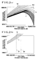
- the position of the focus-compensation lens 105 that results in an optical image on the imaging surface of the CCD 106, namely, the focused position of the focus-compensation lens 105 varies with the distance to the object as shown in Fig. 2(a).
- the focused position of the focus-compensation lens 105 varies with the focal length of the zoom lens unit 100, namely, the position of the variator lens 102.
- an optical image is obtained through the light which is focused by shifting the focus-compensation lens 105 according to the curve resulting from the focal length set and the object distance.
- Fig. 4 interpolation applied to the variator lens 102 in its one direction is discussed.
- the position of the variator lens 102 is arbitrarily set, and representative (cam) locus (the positions of the focus-compensation lens relative to the variator lens) is a plot of the positions of the variator lens 102, z0, z1, z2, ..., zn and a0, a1, a2, ..., an, and b0, b1, b2, ..., bn relative to the object distance.
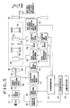
- Fig. 5 is a block diagram showing the lens control device according to a first embodiment of the present invention.
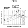
- Fig. 12 shows the locus of the position of a focus-compensation lens with the wide-angle attachment lens mounted, wherein the slope of the locus differs from that of the locus obtained with no wide-angle attachment lens mounted.
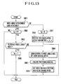
- Fig. 13 is a flow diagram showing the preparatory processing routine in the camera according to a third embodiment of the present invention with the wide-angle attachment lens mounted.
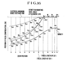
- Fig. 16 shows the locus of the position of the focus-compensation lens with the wide-angle attachment lens mounted, wherein the slope of the locus differs from that of the locus obtained with no wide-angle attachment lens mounted.
- Fig. 17 is a block diagram showing the camera according to a fourth embodiment of the present invention.
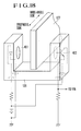
- Fig. 18 is a perspective view showing the arrangement of a position detecting switch and a photosensor used in the camera of Fig. 17.
- Fig. 22 is a flow diagram showing the reset operation at the manual mode startup in the camera according to the fifth embodiment of the present invention with the wide-angle attachment lens mounted.
- Fig. 23 is a flow diagram showing the calculation method of a return position of the focus-compensation lens with the wide-angle attachment lens mounted.
- Fig. 5 is the block diagram showing the construction of a video camera into which the lens control device of the present invention is implemented.
- the camera in this embodiment is provided with a zoom lens unit 100 that is capable of adjusting its focal length within a first focal length area and power within a range from 1x to 12x.
- the zoom lens unit 100 comprises a first lens group 101.
- a second lens group (hereinafter referred to as "a variator lens") 102 which shares the same optical axis with the first lens group 101.
- the iris control circuit 112 generates a control signal that controls openness of the iris 103 in accordance with the level of input video signal.
- the control signal from the iris control circuit 112 is fed to an IG driver 113.
- the IG driver 113 drives its IG meter 113a. With the IG meter 113a driven, openness of the iris 103 is controlled so that the level of video signal remains constant. Light quantity is thus adjusted.
- the focus-compensation lens driver 119 drives the focus-compensation motor 120 to move the focus-compensation lens 105 along its optical axis.
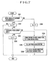
- the initial setting is performed at the start of the processing (step S201).
- the RAM and the variety of ports at the AF microcomputer 115 are initialized.
- a communication routine follows (step S202).
- the focal length information such as the operational information of the zoom switch unit 125 and the position of the variator lens, the direction in which the variator lens is driven under the zoom control of the AF microcomputer 115, namely the zoom driving direction, and information indicative of the operative zoom driving area which is changed according to the presence or absence of the wide-angle attachment lens 121 on the zoom lens unit 100.
- the system controller 124 controls the character generator 126 in order to present each necessary pieces of information on LCD 111.
- the AF processing routine takes place (step S204).
- several operations such as integrating operation, peak detection, difference calculus are performed to the AF evaluation signals such as high frequency components, and automatic focus adjustment is performed based on variations in the AF evaluation signals.
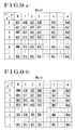
- the follow processing routine is the process to follow the movement of the variator lens 102 according to the representative cam locus tables stored in the AF microcomputer 115 such as the ones shown in Figs. 9(a) and 9(b).
- the representative cam locus table lists data representing the relationship between the focal length (the position of the variator lens) and the position of the focus-compensation lens with no wide-angle attachment lens mounted. Listed in this table are representative values representing the above relationship.
- the other table in Fig. 9(b) lists data representing the relationship between the focal length (the position of the variator lens) and the position of the focus-compensation lens with the wide-angle attachment lens mounted.
- n Listed in this table are representative values representing the above relationship.
- the leftmost column v lists the position of the variator lens 102, and the topmost row n lists object distance.
- the degree of unfocusing is minimized by allowing the focus-compensation lens to follow the 10 cm cam locus f2 with no wide-angle attachment lens mounted, which is most closely positioned to the locus of infinity object distance with the wide-angle attachment lens mounted, in the course of movement of the variator lens into within the focusable focal length area.
- the driving operation of the focus-compensation lens 105 performed on the basis of the focus driving direction and the focus driving speed is discussed in detail.
- the construction of the camera in this embodiment remains unchanged from that of the camera in the first embodiment.
- the locus with the wide-angle attachment lens mounted as shown in Fig. 2(b) is stored as tabled data in the AF microcomputer 115 and is used to avoid an unfocused state.
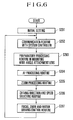
- zoom area v is calculated to locate the zoom area v within which the position Zx of the variator lens 102 falls (step S601).
- Fig. 11 shows the detail of step S601.
- the slope of a locus with the wide-angle attachment lens 121 mounted may be different with object distance (such as loci as shown in Fig. 16). If the locus of the infinity object distance is followed in such a case with the wide-angle attachment lens mounted, the focus-compensation lens 105 may shift off its real focused position depending on the object photographed. Thus, an unfocused state results, deteriorating image quality.
- the zoom area calculation is performed to identify the zoom area v in which the variator lens 102 currently lies (step S1001). The content of this processing remains substantially unchanged from that illustrated in Fig. 11.
- the forced zoom operation into the focusable focal length area is performed without creating unfocused state regardless of the object distance that was used immediately before the mounting of the wide-angle attachment lens. Also, the forced zoom operation is performed while keeping an object in focus even if the slope of the locus of object distance greatly varies with object distance as a result of mounting the wide-angle attachment lens 121.
- the focused position of the focus-compensation lens 105 varies with the object distance as shown in Fig. 2(b). With the object distance kept constant, the focused position of the focus-compensation lens 105 varies with focal length, namely with the position of the variator lens 102. As can be seen from Fig. 2(b), however, the curve representing the relationship, in terms of object distance as parameter, between the focal length and the position of the focus-compensation lens 105 is different from the curve representing the relationship, in terms of object distance as parameter, between the focal length and the position of the focus-compensation lens 105 with no wide-angle attachment lens 121 mounted. In Fig.
- the variator lens 102 When the wide-angle attachment lens 121 is mounted with the zoom lens unit 100 positioned on the telephoto side, the variator lens 102 is forced to move closer to the wide-angle side. In the course of this movement, an unfocused state takes place.
- the object of this embodiment is to provide a camera, which avoids an operator's confusion attributed to the fact that the mounting of a conversion lens group such as a wide-angle attachment lens goes unnoticed, and which offers an improved image quality and improved automatic focus adjustment performance.
- this embodiment comprises a zoom lens unit having a variator lens group and a focus-compensation lens group which compensates for in a focused position a variation arising from power variation operation of the variator lens group, a conversion lens group mounted onto the zoom lens unit in a detachable manner, for shifting a focusable focal length area of the zoom lens unit to a second focal length area from a first focal length area while the conversion lens group is mounted, position detecting means for detecting a position of the focus-compensation lens group on the basis of a predetermined reference position, and reference position shifting means for shifting the predetermined reference position to a reference position corresponding to the second focal length area when the conversion lens group is mounted on the zoom lens unit.
- the variator lens 102 contains a photosensor 128 for detecting whether the variator lens 102 is situated at its reference position or not.
- the optical path of the photosensor 128 is opened or closed by a position detecting switch 127.
- the position detecting switch 127 is attached onto the lens casing.
- the position detecting switch 127 is mounted with its boundary, between block and transmission of light, coming to the middle of the range of travel of the variator lens 102.
- the movement of the photosensor 128 relative to the position detecting switch 127 allows the output light to be blocked or transmitted.
- the signal responsive to the output light transitions from H (high) to L (low) level.
- the point of this signal transition is identified as the reference position.
- a determination is made of whether the variator lens 102 is positioned at the reference position or not.
- the focus-compensation lens 105 contains a photosensor 130 for detecting whether the focus-compensation lens 105 is situated at its reference position or not.
- the optical path of the photosensor 130 is opened or closed by a position detecting switch 129.
- the position detectingr switch 129 is attached onto the lens casing.
- the position detecting switch 129 is mounted with its boundary, between block and transmission of light, coming to the middle of the range of travel of the focus-compensation lens 105.
- the movement of the photosensor 130 relative to the position detecting switch 129 allows the output light to be blocked or transmitted.
- the signal responsive to the output light transitions from H to L level. The point of this signal transition is identified as the reference position.
- a determination is made of whether the focus-compensation lens 105 is positioned at the reference position or not.
- the outputs of the photosensors 128, 130 are read into the AF microcomputer 115.
- Each of the positions of the variator lens 102 and the focus-compensation lens 105 is detected by counting the driving pulse for the respective driving stepping motor by means of the respective counter in the AF microcomputer 115.
- the mounting of the wide-angle attachment lens 121 is detected by the wide-angle attachment lens mounting detecting switch 123, and its output is sent to the AF microcomputer 115.
- the position of the position detecting switch 129 that transitions the output of the photosensor 130 in level is used to reset the position counter of the focus-compensation lens 105.
- each lens counter is executed by the AF microcomputer 115.
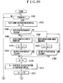
- a determination is made of whether power is switched on or not (step S1301). When power is not switched on, a wait state is kept. When power is switched on, a count Cz at a zoom lens position counter is cleared (step S1302), and a determination is made of whether the output signal of the photosensor 128 is at an H level or not (step S1303). For example, when the boundary between block and transmission of light is at the middle of the range of travel of the variator lens 102, the output signal level of the photosensor 128 identifies whether the boundary is on the telephoto side or on the wide-angle side relative to the current variator lens position. In Fig.
- the variator lens 102 is on the telephoto side relative to the boundary. By moving the variator lens 102 toward the wide-angle side, the output signal level of the photosensor 128 is transitioned from an L level to an H level.
- the operation is the opposite of what has been described above.
- step S1306 a determination is made of whether the output signal level of the photosensor 128 is at an L level or not. When the output signal level of the photosensor 128 is at an H level, the process starts over with step S1304.
- step S1303 When the output signal level of the photosensor 128 is at an L level (step S1303), the variator lens 102 is moved toward the wide-angle side to acquire the boundary point (step S1307).
- the count Cz is decremented by -1 in synchronism with the stepping pulse of the variator lens motor 118 (step S1308).
- the count Cz is once stored as C0 into a memory (step S1310).
- the count Cz indicates, immediately after power on, the value of stepping pulses of the variator lens motor 118 between the position of the variator lens 102 prior to the reset operation and the position detecting switch 127, and this value represents the distance between the position of the variator lens 102 prior to power on and the position of the position detecting switch 127.
- a predetermined numerical value representing the position of the position detecting switch 127 is entered into the zoom lens position counter, and reset operation ends (step S1311).
- the predetermined numerical value for example, may be a pulse count of the stepping pulse of the variator lens motor 118, into which the position of the position detecting switch 127 measured relative to the original point determined from optical design viewpoint within the range of travel of the variator lens 102 is converted.
- step S1312 In succession to the reset operation in step S1311, the already stored C0 is subtracted from the newly determined Cz, and the result replaces C0 in the memory (step S1312).
- C0 is a value corresponding to the position of the variator lens 102 relative to the position of the position detecting switch 127 that is measured relative to the original point (or C0 is a value obtained by subtracting the distance between the position of the position detecting switch 127 and the position of the variator lens 102 from the position of the position detecting switch 127).
- the variator lens 102 must be moved until the count Cz becomes C0.
- C0 stored into the memory at step S1310 is a negative value. If C0 is processed at step S1312, the result is greater than the count Cz obtained at step S1312. This means that the position of the variator lens 102 is originally to the telephoto side, and no problem is thus presented. In this manner, the initial position of the variator lens 102 is determined.
- step S1314 a determination is made of whether C0 is within the focusable focal length area with the wide-angle attachment lens mounted, based on the determination of whether the absolute lens position C0 stored in the memory is greater than Cwa or not (step S1314).
- Cwa corresponds to the focal length, the position 301 of the variator lens 102 in Fig. 2(b).
- step S1316 After resetting C0 again at step S1315, when the wide-angle attachment lens 121 is not mounted or when C0 is not greater than Cwa, a determination is made of whether the return position C0 is equal to a reset value Cz or not (step S1316). When the return position C0 is equal to the reset value Cz, the variator lens 102 is already at the return position, and thus movement of the variator lens 102 is stopped (step S1322).
- step S1317 a determination is made of whether the return position C0 is greater than the reset value Cz.
- step S1318 the variator lens 102 is moved to the telephoto side based on the determination that the return direction is to the telephoto side.
- the return position C0 is equal to or smaller than Cz
- the movement of the variator lens 102 is stopped (step S1322) based on the determination that the variator lens 102 has already reached the return position C0.
- the return position C0 is greater than Cz
- the process starts over with step S1318 based on the determination that the variator lens 102 has yet to reach the return position C0.
- the variator lens 102 is moved to the wide-angle side based on the determination that the return direction is to the wide-angle side (step S1320).
- step S1324 In succession to the stop of movement of the variator lens 102, the ordinary operation of the camera takes place (step S1324). Now that the entire lens reset operation is complete, a photographed image is output in the ordinary photographing activity.
- the fourth embodiment of the present invention thus controls the unfocused image that could be created due to the forced zoom operation when power is switched on with the wide-angle attachment lens mounted.
- the embodiment also avoids an operator's confusion attributed to the fact that the mounting of the wide-angle attachment lens goes unnoticed, and offers an improved image quality and improved automatic focus adjustment performance.
- the reset operation of the zoom lens position counter has been described.
- the same reset operation can be applied to a focus lens position counter.
- the automatic focus adjustment mode follows the reset operation. Therefor, there is no need for the focus-compensation lens 105 to revert back to its initial position after resetting the focus lens position counter.
- the return operation of the variator lens 102 follows the flow diagrams in Figs. 19 and 20, its focused state will be achieved even if the variator lens 102 is at any position.
- an unfocused state takes place if the focus-compensation lens 105 is not moved back to its initial position.
- the focus-compensation lens 105 is on the infinity side relative to the boundary. By moving the focus-compensation lens 105 toward the minimum side, the output signal level of the photosensor 130 is transitioned from an L level to an H level.
- the output signal level of the photosensor 130 is initially at an H level, the operation is the opposite of what has been described above.
- step S1510 a determination is made of whether the output signal level of the photosensor 130 is at an H level or not.
- the process starts over with step S1508.
- step S1517 a determination is made of whether the return position Cf0 is equal to the value Cf or not (step S1517).
- the focus-compensation lens 105 has already arrived at the return position, and the movement of the focus-compensation lens 105 is stopped (step S1523).
- step S1520 a determination is made of whether the return position Cf0 is equal to or smaller than Cf (step S1520).
- the return position Cf0 is equal to or greater than Cf
- the movement of the focus-compensation lens 105 is stopped (step S1523) based on the determination that the focus-compensation lens 105 has already arrived at the return position Cf0.
- the return position Cf0 is greater than Cf
- the process starts over with step S1519.
- step S1522 a determination is made of whether the return position Cf0 is equal to or greater than Cf (step S1522).
- the return position Cf0 is equal to or greater than Cf
- the movement of the focus-compensation lens 105 is stopped based on the determination that the focus-compensation lens 105 has already arrived at the return position Cf0 (step S1523).
- the return position Cf0 is smaller than Cf, the process starts over with step S1521.
- step S1525 a determination is made of whether power is interrupted or not (step S1525). When power is interrupted, the program returns to step S1501. When power is not interrupted, the ordinary operation is continued.
- the position C2 of the variator lens 102 prior to power on is stored as zp (step S1701).
- the zoom area calculation is performed to determine the zoom area v in the tabled data in which the position zx of the variator lens 102 lies (step S1702).
- C(v) (Telephoto end zoom position - Wide-angle end zoom position) * v/s + Wide-angle end zoom position
- the division operation by the value s is to equally divide the overall range of travel of the variator lens by the zoom area number s in Fig. 9(a).
- step S2103 a determination is made of whether the position zp of the variator lens 102 equals the position C(v) (step S2103).
- a boundary flag is raised to "1" based on the determination that the position zp of the variator lens 102 lies on the boundary of the area v (step S2107). This completes step S1702.
- step S2104 a determination is made of whether the position zp of the variator lens 102 is smaller than the position C(v) (step S2104).
- the boundary flag is set to "0" (step S2106) based on the determination that the position zp of the variator lens 102 is somewhere between C(v-1) and C(v). This completes step S1702.
- the boundary flag is "1," the object distance n, focused position of the focus-compensation lens 105 A(n,v), A(n+1,v) relative to the variator lens 102 are read, and A(n,v) and A(n+1,v) are stored as ax and bx (step S1708).
- step S1709 When Cf0 is not greater than ax (step S1709), Cf0 is at the super-infinity position. "0" is stored as locus parameter ⁇ , the difference, bx-ax, is stored as locus parameter ⁇ , and the object distance n is stored as locus parameter ⁇ (steps S1713, S1715 and S1716).
- Locus parameters, ⁇ , ⁇ , and ⁇ representing where the position of the variator lens 102 and the position of the focus-compensation lens 105 are on the locus are sequentially updated and stored and then used as the object distance information immediately before the mounting of the wide-angle attachment lens.
- the boundary flag is set to "0,” C0 is considered to be not on the boundary of the zoom area.
- the boundary flag is set to "1," C0 is considered to be on the boundary of the zoom area.
- initialization of the position detecting means is performed by shifting the compensation lens group to the reference position.
- the error in position sensing by the position detecting means is controlled.
Landscapes
- Engineering & Computer Science (AREA)
- Multimedia (AREA)
- Signal Processing (AREA)
- Physics & Mathematics (AREA)
- General Physics & Mathematics (AREA)
- General Engineering & Computer Science (AREA)
- Optics & Photonics (AREA)
- Lens Barrels (AREA)
- Structure And Mechanism Of Cameras (AREA)
Claims (13)
- Dispositif à lentilles pour commander un système de lentilles, le dispositif comprenant :une première lentille (101) mobile pour faire varier la puissance du système de lentilles ;une seconde lentille (105) pour compenser les variations de la position focale qui sont dues au mouvement de la première lentille ;et un moyen (122) à l'aide duquel une troisième lentille (121) peut être montée de façon amovible sur l'axe optique des première et seconde lentilles, et caractérisé par :un moyen de commande (124) pour modifier la plage de mouvement de la première lentille d'une première région vers une seconde région en réponse au montage d'une troisième lentille, et pour confiner la plage de mouvement de la seconde lentille de façon que la seconde lentille soit capable de compenser la variation de la position focale qui est due au mouvement de la première lentille dans la seconde région en fonction du mouvement de la première lentille de la première région vers la seconde région.
- Dispositif selon la revendication 1, dans lequel ledit moyen de commande a une mémoire qui stocke des informations concernant le lieu de la seconde lentille pour maintenir l'état focalisé du système de lentilles pendant le mouvement de la première lentille à l'intérieur de sa première région de déplacement, et est adapté à commander la seconde lentille sur la base du lieu de déplacement de la première lentille à l'intérieur de la première région de déplacement lorsque la première lentille est déplacée de la première région vers la seconde région.
- Dispositif selon la revendication 2, dans lequel ledit moyen de commande est, en réponse à des informations stockées dans ladite mémoire, adapté à commander la seconde lentille sur la base d'une version corrigée dudit lieu à l'intérieur de la première plage de déplacement lorsque la première lentille est déplacée de la première région vers la seconde région.
- Dispositif selon la revendication 3, dans lequel ledit moyen de commande comprend une première mémoire pour stocker des informations concernant le lieu de la seconde lentille afin de maintenir le système de lentilles dans son état focalisé pendant le mouvement de la première lentille à l'intérieur de ladite première région et une seconde mémoire pour stocker des informations concernant le lieu de la seconde lentille afin de maintenir le système de lentilles à l'état focalisé pendant le mouvement de la première lentille à l'intérieur de ladite seconde région, et commande la position de la seconde lentille en fonction des informations stockées dans l'une ou l'autre de la première mémoire et de la seconde mémoire selon la position de la première lentille.
- Dispositif selon la revendication 4, dans lequel ledit moyen de commande est adapté à commander la seconde lentille sur la base de l'un des lieux de la première lentille à l'intérieur de la première région, ce lieu étant le plus proche de la seconde région, lorsque la plage de déplacement de la première lentille est décalée de la première zone vers la seconde zone.
- Dispositif selon l'une quelconque des revendications précédentes, dans lequel ledit moyen de commande est adapté à détecter une distance d'objet correspondant à la position de la seconde lentille immédiatement avant le montage de la troisième lentille, et lorsque la troisième lentille est montée, pour lire le lieu correspondant à la distance d'objet déterminée par rapport au lieu de la seconde lentille à l'intérieur de la seconde région stockée dans la mémoire lorsque la première lentille est déplacée vers la seconde région, et pour commander la seconde lentille sur la base du lieu lu.
- Dispositif selon l'une quelconque des revendications précédentes, dans lequel ladite seconde région est définie comme étant du côté à grand angle par rapport à la première région.
- Dispositif selon la revendication 7, dans lequel ledit moyen de montage est adapté au montage d'une lentille à grand angle, et les moyens de commande sont conçus pour décaler vers le côté à grand angle la plage de déplacement de la première lentille qui peut être focalisée par la seconde lentille.
- Dispositif selon l'une quelconque des revendications précédentes, dans lequel lesdits moyens de commande sont adaptés à commander à la fois la direction d'entraínement et la vitesse d'entraínement de la seconde lentille pendant que la première lentille est déplacée de la première région vers la seconde région en utilisant des informations de commande concernant la seconde lentille pendant la phase lors de laquelle la plage de déplacement de la première lentille est décalée de la première région vers la seconde région.
- Appareil de prise de vues, comprenant :un dispositif de commande de lentilles selon l'une quelconque des revendications précédentes et comprenant :des moyens de prise de vues (111) pour convertir une image optique incidente qui est introduite à travers les première et seconde lentilles en un signal vidéo, et un écran (110) pour afficher un signal vidéo fourni en sortie par lesdits moyens de prise de vues, lesdits moyens de commande étant adaptés à désactiver l'affichage du signal vidéo sur les moyens d'affichage pendant que la plage de déplacement de la première lentille est décalée de la première région vers la seconde région.
- Appareil selon la revendication 10, comportant en outre des moyens de détection de position pour détecter la position de la première lentille, lesdits moyens de commande étant adaptés à modifier une position de référence utilisée pour initialiser les moyens de détection de position en fonction de la position détectée de la première lentille.
- Appareil selon la revendication 11, dans lequel une position de référence est fixée dans chacune des première et seconde régions.
- Appareil selon la revendication 12, dans lequel les moyens de commande sont adaptés à modifier la position de référence utilisée pour initialiser les moyens de détection de position en fonction de la position de la première lentille lors de la mise sous tension.
Applications Claiming Priority (6)
| Application Number | Priority Date | Filing Date | Title |
|---|---|---|---|
| JP98029/94 | 1994-04-12 | ||
| JP9802994A JPH07281072A (ja) | 1994-04-12 | 1994-04-12 | カメラ |
| JP9802894 | 1994-04-12 | ||
| JP9802994 | 1994-04-12 | ||
| JP09802894A JP3466700B2 (ja) | 1994-04-12 | 1994-04-12 | カメラ |
| JP98028/94 | 1994-04-12 |
Publications (3)
| Publication Number | Publication Date |
|---|---|
| EP0677760A2 EP0677760A2 (fr) | 1995-10-18 |
| EP0677760A3 EP0677760A3 (fr) | 1996-01-17 |
| EP0677760B1 true EP0677760B1 (fr) | 2000-10-11 |
Family
ID=26439202
Family Applications (1)
| Application Number | Title | Priority Date | Filing Date |
|---|---|---|---|
| EP95302346A Expired - Lifetime EP0677760B1 (fr) | 1994-04-12 | 1995-04-10 | Dispositif à contrôle de lentille |
Country Status (6)
| Country | Link |
|---|---|
| US (1) | US6744468B2 (fr) |
| EP (1) | EP0677760B1 (fr) |
| KR (1) | KR0173159B1 (fr) |
| CN (1) | CN1114126C (fr) |
| DE (1) | DE69519050T2 (fr) |
| SG (2) | SG102527A1 (fr) |
Families Citing this family (19)
| Publication number | Priority date | Publication date | Assignee | Title |
|---|---|---|---|---|
| US6683652B1 (en) * | 1995-08-29 | 2004-01-27 | Canon Kabushiki Kaisha | Interchangeable lens video camera system having improved focusing |
| US6989865B1 (en) * | 1997-12-19 | 2006-01-24 | Canon Kabushiki Kaisha | Optical equipment and it control method, and computer-readable storage medium |
| JP3530906B2 (ja) * | 2001-03-30 | 2004-05-24 | ミノルタ株式会社 | 結像位置検出プログラムおよびカメラ |
| KR20040062247A (ko) * | 2003-01-02 | 2004-07-07 | 엘지전자 주식회사 | 홍채 인식 카메라의 구조 및 그 사용 방법 |
| JP4478419B2 (ja) * | 2003-09-02 | 2010-06-09 | キヤノン株式会社 | レンズ制御装置、光学機器およびレンズ制御方法 |
| US7415200B2 (en) * | 2003-10-14 | 2008-08-19 | Canon Kabushiki Kaisha | Imaging device |
| JP4551708B2 (ja) * | 2004-07-21 | 2010-09-29 | キヤノン株式会社 | 撮像装置 |
| JP2008058399A (ja) * | 2006-08-29 | 2008-03-13 | Canon Inc | 焦点調節装置、撮像装置、および制御方法 |
| KR100880672B1 (ko) * | 2007-07-18 | 2009-02-02 | 자화전자 주식회사 | 자동초점 기능을 구비한 카메라 시스템 및 그 제어방법 |
| JP5574729B2 (ja) * | 2010-02-03 | 2014-08-20 | キヤノン株式会社 | レンズ制御装置、その制御方法及びプログラム |
| JP5590903B2 (ja) * | 2010-02-05 | 2014-09-17 | キヤノン株式会社 | 撮像レンズ、撮像装置、及び撮像装置の制御方法 |
| JP5750694B2 (ja) * | 2011-03-25 | 2015-07-22 | オリンパス株式会社 | 交換レンズ |
| KR101293245B1 (ko) * | 2012-02-21 | 2013-08-09 | (주)비에이치비씨 | 광학 줌 카메라의 줌 트래킹 자동 초점 제어기 및 그 제어 방법 |
| JP6003199B2 (ja) * | 2012-05-08 | 2016-10-05 | ソニー株式会社 | レンズ交換式カメラシステムおよびレンズデータ取得プログラム |
| JP2016006480A (ja) * | 2014-05-27 | 2016-01-14 | パナソニックIpマネジメント株式会社 | 撮像装置 |
| EP3955057B1 (fr) * | 2017-05-31 | 2023-05-10 | Canon Kabushiki Kaisha | Appareil d'imagerie, accessoire intermédiaire et procédés de commande associés |
| CN113777738A (zh) * | 2020-06-08 | 2021-12-10 | 华为技术有限公司 | 变焦镜组、镜头组件、摄像装置、电子设备及变焦方法 |
| CN113900211B (zh) * | 2020-06-18 | 2023-05-05 | 华为技术有限公司 | 自动聚焦组件、摄像装置、电子设备和自动聚焦方法 |
| CN115079369B (zh) * | 2022-05-25 | 2023-12-26 | 北京都视科技有限公司 | 镜头模组的光学对焦方法、装置、存储介质以及镜头模组 |
Family Cites Families (17)
| Publication number | Priority date | Publication date | Assignee | Title |
|---|---|---|---|---|
| JPH0654366B2 (ja) * | 1985-05-20 | 1994-07-20 | ウエスト電気株式会社 | ズ−ミング方法およびズ−ミング装置 |
| US4994842A (en) * | 1987-02-06 | 1991-02-19 | Minolta Camera Kabushiki Kaisha | Camera having a converter-attachable zoom lens |
| JP2776482B2 (ja) * | 1988-08-23 | 1998-07-16 | 株式会社リコー | レンズ制御装置 |
| US5144491A (en) | 1989-04-24 | 1992-09-01 | Canon Kabushiki Kaisha | Apparatus with lens control device |
| US5122880A (en) * | 1989-05-29 | 1992-06-16 | Canon Kabushiki Kaisha | Electronic still camera with lessened power consumption |
| JP2728943B2 (ja) | 1989-07-08 | 1998-03-18 | キヤノン株式会社 | レンズ制御装置 |
| JPH0348212A (ja) | 1989-07-17 | 1991-03-01 | Fuji Photo Film Co Ltd | ズームレンズ装置 |
| US5323200A (en) * | 1991-05-22 | 1994-06-21 | Canon Kabushiki Kaisha | Optical apparatus having lens control device |
| US5638217A (en) * | 1991-08-20 | 1997-06-10 | Canon Kabushiki Kaisha | Lens control device |
| JPH05145817A (ja) * | 1991-11-21 | 1993-06-11 | Canon Inc | ビデオカメラ |
| JPH05145819A (ja) * | 1991-11-21 | 1993-06-11 | Canon Inc | ビデオカメラ |
| US5296970A (en) | 1992-03-30 | 1994-03-22 | Fuji Photo Optical Co., Ltd | Zoom lens system |
| DE69326106T2 (de) * | 1992-06-29 | 2000-01-05 | Canon K.K., Tokio/Tokyo | Objektivkontrollgerät |
| US5790902A (en) * | 1993-09-02 | 1998-08-04 | Canon Kabushiki Kaisha | Zoom lens |
| KR950023062A (ko) * | 1993-12-21 | 1995-07-28 | 이헌조 | 비디오 카메라의 플랜지백 조정방법 |
| US5786853A (en) * | 1994-04-12 | 1998-07-28 | Canon Kabushiki Kaisha | Lens control device |
| JP3610167B2 (ja) * | 1996-07-30 | 2005-01-12 | キヤノン株式会社 | レンズ制御方法及び装置 |
-
1995
- 1995-04-10 SG SG9800306A patent/SG102527A1/en unknown
- 1995-04-10 EP EP95302346A patent/EP0677760B1/fr not_active Expired - Lifetime
- 1995-04-10 DE DE69519050T patent/DE69519050T2/de not_active Expired - Lifetime
- 1995-04-10 SG SG9800302A patent/SG102526A1/en unknown
- 1995-04-12 KR KR1019950008462A patent/KR0173159B1/ko not_active Expired - Fee Related
- 1995-04-12 CN CN95104340A patent/CN1114126C/zh not_active Expired - Fee Related
-
1998
- 1998-01-13 US US09/006,567 patent/US6744468B2/en not_active Expired - Fee Related
Also Published As
| Publication number | Publication date |
|---|---|
| KR950029833A (ko) | 1995-11-24 |
| DE69519050T2 (de) | 2001-10-25 |
| EP0677760A3 (fr) | 1996-01-17 |
| SG102527A1 (en) | 2004-03-26 |
| EP0677760A2 (fr) | 1995-10-18 |
| SG102526A1 (en) | 2004-03-26 |
| US6744468B2 (en) | 2004-06-01 |
| KR0173159B1 (ko) | 1999-05-01 |
| DE69519050D1 (de) | 2000-11-16 |
| CN1116726A (zh) | 1996-02-14 |
| US20020135693A1 (en) | 2002-09-26 |
| CN1114126C (zh) | 2003-07-09 |
Similar Documents
| Publication | Publication Date | Title |
|---|---|---|
| EP0677760B1 (fr) | Dispositif à contrôle de lentille | |
| EP0677761B1 (fr) | Dispositif à contrôle de lentille | |
| KR101753367B1 (ko) | 영상 처리 장치 | |
| EP2339827A2 (fr) | Système autofocus | |
| US7349013B2 (en) | Imaging apparatus having a lens device for a zooming control operation and the method of using the same | |
| EP1065549B1 (fr) | Dispositif optique, unité d'entraînement pour le déplacement d'un élément optique et système de photographie | |
| US6184932B1 (en) | Lens control apparatus | |
| JP3610176B2 (ja) | 撮像装置、その制御方法、及びレンズ制御装置 | |
| EP1598687B1 (fr) | Dispositif de commande d'entrainement pour dispositif à lentille | |
| US20040179129A1 (en) | Image pickup apparatus, control method for the same, and program for implementing the control method | |
| US5315340A (en) | Video camera apparatus | |
| JPH1164956A (ja) | レンズ装置、撮像装置及びコンピュータ読み取り可能な記録媒体 | |
| US20050083428A1 (en) | Image pickup apparatus | |
| EP3598222A1 (fr) | Appareil de réglage de mise au point, appareil de capture d'image, procédé de réglage de mise au point, support d'informations et programme | |
| EP0989747B1 (fr) | Appareil d'objectif de télévision adapté pour un studio virtuel | |
| JPH1039192A (ja) | 撮像方法及び装置並びに記憶媒体 | |
| JPH10325918A (ja) | ズームレンズ装置 | |
| KR100237199B1 (ko) | 3차원 영상 기록/재생 장치 | |
| KR101417803B1 (ko) | 디지털 영상 처리장치 | |
| JPH04213972A (ja) | フオ─カス調整装置 | |
| JP2004274515A (ja) | 撮像装置 | |
| JPH11252436A (ja) | 電子カメラ | |
| JPH04196685A (ja) | ビデオカメラの表示装置 | |
| JPH07281072A (ja) | カメラ | |
| JPH0421277A (ja) | 焦点調節装置 |
Legal Events
| Date | Code | Title | Description |
|---|---|---|---|
| PUAI | Public reference made under article 153(3) epc to a published international application that has entered the european phase |
Free format text: ORIGINAL CODE: 0009012 |
|
| AK | Designated contracting states |
Kind code of ref document: A2 Designated state(s): DE ES FR GB NL |
|
| PUAL | Search report despatched |
Free format text: ORIGINAL CODE: 0009013 |
|
| AK | Designated contracting states |
Kind code of ref document: A3 Designated state(s): DE ES FR GB NL |
|
| 17P | Request for examination filed |
Effective date: 19960530 |
|
| 17Q | First examination report despatched |
Effective date: 19981014 |
|
| GRAG | Despatch of communication of intention to grant |
Free format text: ORIGINAL CODE: EPIDOS AGRA |
|
| GRAG | Despatch of communication of intention to grant |
Free format text: ORIGINAL CODE: EPIDOS AGRA |
|
| GRAH | Despatch of communication of intention to grant a patent |
Free format text: ORIGINAL CODE: EPIDOS IGRA |
|
| GRAH | Despatch of communication of intention to grant a patent |
Free format text: ORIGINAL CODE: EPIDOS IGRA |
|
| GRAA | (expected) grant |
Free format text: ORIGINAL CODE: 0009210 |
|
| AK | Designated contracting states |
Kind code of ref document: B1 Designated state(s): DE ES FR GB NL |
|
| PG25 | Lapsed in a contracting state [announced via postgrant information from national office to epo] |
Ref country code: NL Free format text: LAPSE BECAUSE OF FAILURE TO SUBMIT A TRANSLATION OF THE DESCRIPTION OR TO PAY THE FEE WITHIN THE PRESCRIBED TIME-LIMIT Effective date: 20001011 Ref country code: ES Free format text: THE PATENT HAS BEEN ANNULLED BY A DECISION OF A NATIONAL AUTHORITY Effective date: 20001011 |
|
| REF | Corresponds to: |
Ref document number: 69519050 Country of ref document: DE Date of ref document: 20001116 |
|
| ET | Fr: translation filed | ||
| NLV1 | Nl: lapsed or annulled due to failure to fulfill the requirements of art. 29p and 29m of the patents act | ||
| PLBE | No opposition filed within time limit |
Free format text: ORIGINAL CODE: 0009261 |
|
| STAA | Information on the status of an ep patent application or granted ep patent |
Free format text: STATUS: NO OPPOSITION FILED WITHIN TIME LIMIT |
|
| 26N | No opposition filed | ||
| REG | Reference to a national code |
Ref country code: GB Ref legal event code: IF02 |
|
| PGFP | Annual fee paid to national office [announced via postgrant information from national office to epo] |
Ref country code: DE Payment date: 20130430 Year of fee payment: 19 Ref country code: GB Payment date: 20130418 Year of fee payment: 19 |
|
| PGFP | Annual fee paid to national office [announced via postgrant information from national office to epo] |
Ref country code: FR Payment date: 20130517 Year of fee payment: 19 |
|
| REG | Reference to a national code |
Ref country code: DE Ref legal event code: R119 Ref document number: 69519050 Country of ref document: DE |
|
| GBPC | Gb: european patent ceased through non-payment of renewal fee |
Effective date: 20140410 |
|
| REG | Reference to a national code |
Ref country code: FR Ref legal event code: ST Effective date: 20141231 |
|
| REG | Reference to a national code |
Ref country code: DE Ref legal event code: R119 Ref document number: 69519050 Country of ref document: DE Effective date: 20141101 |
|
| PG25 | Lapsed in a contracting state [announced via postgrant information from national office to epo] |
Ref country code: GB Free format text: LAPSE BECAUSE OF NON-PAYMENT OF DUE FEES Effective date: 20140410 Ref country code: DE Free format text: LAPSE BECAUSE OF NON-PAYMENT OF DUE FEES Effective date: 20141101 |
|
| PG25 | Lapsed in a contracting state [announced via postgrant information from national office to epo] |
Ref country code: FR Free format text: LAPSE BECAUSE OF NON-PAYMENT OF DUE FEES Effective date: 20140430 |