EP0677954A2 - Procédé pour constituer un paquet de données d'une sous-image comportant des données d'une sous-image superdosé sur une image principale, milieu d'enregistrement pour enregistrer le paquet de données de la sous-image et dispositif de traitement d'image - Google Patents
Procédé pour constituer un paquet de données d'une sous-image comportant des données d'une sous-image superdosé sur une image principale, milieu d'enregistrement pour enregistrer le paquet de données de la sous-image et dispositif de traitement d'image Download PDFInfo
- Publication number
- EP0677954A2 EP0677954A2 EP95302498A EP95302498A EP0677954A2 EP 0677954 A2 EP0677954 A2 EP 0677954A2 EP 95302498 A EP95302498 A EP 95302498A EP 95302498 A EP95302498 A EP 95302498A EP 0677954 A2 EP0677954 A2 EP 0677954A2
- Authority
- EP
- European Patent Office
- Prior art keywords
- sub image
- data
- display
- sub
- assigning
- Prior art date
- Legal status (The legal status is an assumption and is not a legal conclusion. Google has not performed a legal analysis and makes no representation as to the accuracy of the status listed.)
- Granted
Links
- 238000000034 method Methods 0.000 title claims description 55
- 230000002123 temporal effect Effects 0.000 abstract description 13
- 238000010586 diagram Methods 0.000 description 30
- 238000010276 construction Methods 0.000 description 6
- 230000005540 biological transmission Effects 0.000 description 5
- 239000003086 colorant Substances 0.000 description 5
- 230000006870 function Effects 0.000 description 3
- 238000007792 addition Methods 0.000 description 2
- 230000003287 optical effect Effects 0.000 description 1
Images









Classifications
-
- G—PHYSICS
- G11—INFORMATION STORAGE
- G11B—INFORMATION STORAGE BASED ON RELATIVE MOVEMENT BETWEEN RECORD CARRIER AND TRANSDUCER
- G11B5/00—Recording by magnetisation or demagnetisation of a record carrier; Reproducing by magnetic means; Record carriers therefor
- G11B5/62—Record carriers characterised by the selection of the material
-
- H—ELECTRICITY
- H04—ELECTRIC COMMUNICATION TECHNIQUE
- H04N—PICTORIAL COMMUNICATION, e.g. TELEVISION
- H04N21/00—Selective content distribution, e.g. interactive television or video on demand [VOD]
- H04N21/40—Client devices specifically adapted for the reception of or interaction with content, e.g. set-top-box [STB]; Operations thereof
- H04N21/41—Structure of client; Structure of client peripherals
- H04N21/426—Internal components of the client ; Characteristics thereof
- H04N21/42653—Internal components of the client ; Characteristics thereof for processing graphics
-
- H—ELECTRICITY
- H04—ELECTRIC COMMUNICATION TECHNIQUE
- H04N—PICTORIAL COMMUNICATION, e.g. TELEVISION
- H04N5/00—Details of television systems
- H04N5/222—Studio circuitry; Studio devices; Studio equipment
- H04N5/262—Studio circuits, e.g. for mixing, switching-over, change of character of image, other special effects ; Cameras specially adapted for the electronic generation of special effects
- H04N5/272—Means for inserting a foreground image in a background image, i.e. inlay, outlay
-
- H—ELECTRICITY
- H04—ELECTRIC COMMUNICATION TECHNIQUE
- H04N—PICTORIAL COMMUNICATION, e.g. TELEVISION
- H04N5/00—Details of television systems
- H04N5/44—Receiver circuitry for the reception of television signals according to analogue transmission standards
- H04N5/445—Receiver circuitry for the reception of television signals according to analogue transmission standards for displaying additional information
- H04N5/44504—Circuit details of the additional information generator, e.g. details of the character or graphics signal generator, overlay mixing circuits
-
- H—ELECTRICITY
- H04—ELECTRIC COMMUNICATION TECHNIQUE
- H04N—PICTORIAL COMMUNICATION, e.g. TELEVISION
- H04N9/00—Details of colour television systems
- H04N9/64—Circuits for processing colour signals
- H04N9/641—Multi-purpose receivers, e.g. for auxiliary information
-
- H—ELECTRICITY
- H04—ELECTRIC COMMUNICATION TECHNIQUE
- H04N—PICTORIAL COMMUNICATION, e.g. TELEVISION
- H04N5/00—Details of television systems
- H04N5/44—Receiver circuitry for the reception of television signals according to analogue transmission standards
- H04N5/445—Receiver circuitry for the reception of television signals according to analogue transmission standards for displaying additional information
- H04N5/45—Picture in picture, e.g. displaying simultaneously another television channel in a region of the screen
-
- H—ELECTRICITY
- H04—ELECTRIC COMMUNICATION TECHNIQUE
- H04N—PICTORIAL COMMUNICATION, e.g. TELEVISION
- H04N5/00—Details of television systems
- H04N5/76—Television signal recording
- H04N5/91—Television signal processing therefor
- H04N5/92—Transformation of the television signal for recording, e.g. modulation, frequency changing; Inverse transformation for playback
- H04N5/9201—Transformation of the television signal for recording, e.g. modulation, frequency changing; Inverse transformation for playback involving the multiplexing of an additional signal and the video signal
- H04N5/9206—Transformation of the television signal for recording, e.g. modulation, frequency changing; Inverse transformation for playback involving the multiplexing of an additional signal and the video signal the additional signal being a character code signal
- H04N5/9208—Transformation of the television signal for recording, e.g. modulation, frequency changing; Inverse transformation for playback involving the multiplexing of an additional signal and the video signal the additional signal being a character code signal involving the use of subcodes
Definitions
- the present invention relates to an image process apparatus for superimposing a sub image such as a text on a main image such as a TV image, a method for forming a sub image data packet, and a recording medium thereof.
- the sub image display systems can be roughly categorized as character code system and bit map data system.
- character data for example characters and patterns
- a character generator 81 as character code assigned to characters.
- the character code is transmitted to a sub image display portion 83.
- the character code is temporarily stored in a sub image frame buffer 84 and then required characters are displayed.
- dedicated hardware such as the character generator 81 is required. Since data to be transmitted to a display portion is only character code, the amount of data to be transmitted and display time for display process can be reduced.
- bit map data system since bit map data of sub images are directly transmitted to the display portion, the dedicated hardware that generate sub images corresponding to the character code is not required.
- the shapes of sub images that can be displayed are not limited, the applications for displaying sub images are wide.
- bit map data system has losses of data transmission time and display process time.
- each pixel should have sub image color data, sub image contour color data necessary for superimposing a sub image on a main image, and superimpose mixing ration of the main image and sub image.
- the data rate of data to be transmitted to the display portion becomes huge.
- bit map data system since pixel data with the same amount of data for one screen of a main image should be transmitted to the display portion, display spatial loss takes place.
- the data for one screen is referred to as a frame.
- bit map data system is superior to the character code system in effectiveness of sub images.
- bit map data system has display spatial loss and temporal loss.
- An object of the present invention is to provide a sub image data packet forming method, a recording medium, and an image process apparatus that can remarkably reduce display spatial loss and display temporal loss and accomplish sub images that have wide applicabilities.
- the present invention is a method or a recording medium for forming a sub image data packet including data of a sub image superimposed on a main image, the sub image data packet comprising a sub image data portion for storing sub image data for displaying sub image information, a header portion for storing sub image header data for assigning at least a display position, a display size, and a display color of the sub image data, and a control data portion for storing control data for changing the display position, the display size, and the display color of the sub image data assigned by the sub image header data, pixel by pixel.
- the sub image data packet is composed of the sub image data portion, the header portion, and the control data portion.
- the display position, the display size, and the display color of the sub image data portion can be changed for each display unit of the main image.
- losses in the data transmission, the display control, and so forth can be reduced.
- the header portion includes information that represents whether data is present in the sub image data portion and the control data portion. Corresponding to the information, the data structure in the sub image data packet can be changed.
- the data of the control data portion included in the sub image data packet is used as control data for the sub image data portion that is displayed when data is absent in the sub image data portion of the sub image data packet.
- it is not necessary to transmit the same data. Consequently, display spatial loss and display temporal loss can be reduced.
- the display position, the display size, and the display color are not controlled for data in the sub image data portion of the sub image data packet, but displayed corresponding to predetermined default values when data is absent in the control data portion of the sub image data packet.
- the size of the structure of one packet can be reduced. Consequently, temporal loss of data transmission can be reduced.
- the sub image data packet is in a display clear mode and data of the sub image data portion is cleared when data is absent in the sub image data portion and the control data portion. Thus, it is not necessary to newly transmit sub image data portion. Consequently, display spatial loss and display temporal loss can be reduced.
- the header portion includes at least sub image display position/size assigning data for assigning a display position and a display size of the sub image superimposed on the main image corresponding to the type of the main image, display color assigning data for assigning a display color of the sub image, compensating execution assigning data for assigning emphasis of contour of the sub image and so forth, sub image contrast assigning data for assigning a mixing ratio of the sub image and the main image, and sub image display start timing assigning data for assigning from what display unit of the main image the display of the sub image is started.
- the sub image can be superimposed on the main image in various manners.
- the type of data of the sub image data portion includes information that represents data corresponding to field/frame of the main image. Thus, corresponding to the value of the information, the sub image data portion can be recorded.
- a data format of the control data portion is assigned by a change start line number, the number of continuous lines, and the number of pixel change points on each line of a region of the sub image, a pixel number at which a change starts on each change line, a color of the sub image display data after an assigned pixel, a color of a contoured pixel, and a mixing ratio between the main image and the sub image being assigned repeatedly for the number of change lines assigned.
- the data amount of the sub image data packet can be remarkably reduced.
- the end of continuation of the change line is determined by assigning predetermined code to a line number, the number of continuous lines, and the number of pixel change points. Thus, with the packet, the end of the continuation of change lines can be detected.
- the display position, the display size, and the display color are assigned corresponding to the header portion by the control data portion for each display unit of the main image.
- the sub image can be more variously superimposed on the main image than the related art reference.
- Fig. 1 is a schematic diagram showing a construction of a sub image output process system according to the embodiment of the present invention and a structure of image information such as sub image data packet reproduced from an optical disc or the like by the system.
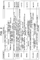
- Fig. 2 is a table showing data structure of a sub image header in the sub image data packet.
- the sub image output process system 1 comprises two sub image display control portions and a display output portion 4.
- the sub image display control portions are a display region control portion 2 and a display timing control portion 3.
- a sub image data packet 5 is composed of three types of data that are a sub image header 6, sub image display data 7, and sub image control data 8.
- the sub image header 6 is control information for assigning the display region on the main image frame and the display manner of the sub image display data 7.
- the data arrangement and data amount of each data in the sub image data packet 5 are not basically limited.
- the sub image header 6 is composed of various control information and so forth that are for example a sub image channel forming mode that is sub image forming information (parameter SPCSTR), a mixing ratio of an sub image and a main image that is a sub image contrast (parameter SPCONT), a sub image display start timing (parameter SPCDST), a sub image display end timing (parameter SPCDEN), a sub image display start position (X, Y), display size such as display width and display height (parameter SPCSIZE), sub image color information (parameter SPCINFO), sub image contour compensating information (parameter SPADJINFO), and sub image control data start address (parameter SPCDADR).
- a sub image channel forming mode that is sub image forming information (parameter SPCSTR), a mixing ratio of an sub image and a main image that is a sub image contrast (parameter SPCONT), a sub image display start timing (parameter SPCDST), a sub image display end timing (parameter SPCDEN), a sub image display start position (X,
- the sub image output process system 1 When the sub image output process system 1 reads the sub image data packet 5, it separates three types of data that are for example the sub image header 6, the sub image display data 7, and the sub image control data 8 from the sub image data packet 5 corresponding to each control information.
- the sub image header 6 is supplied to the display region control portion 2 that controls the display region.
- the sub image control data 8 is supplied to the display timing control portion 3.
- the sub image display data 7 is controlled by the display control portions 2 and 3 and supplied to the display output portion 4.
- the display region control portion 2 controls the display position on the main image frame and the display manner of the sub image display data 7 corresponding to the received sub image header 6.
- the display timing control portion 3 performs a temporal display control such as color change of a sub image and a change of mixing ratio of a main image and a sub image in the condition that the display time interval of one main image frame is one control unit corresponding to the sub image control data 8.
- the display output portion 4 is controlled by the two display control portions 2 and 3 and the sub image display data 7 is displayed and output from the system.
- the sub image output process system 1 displays the next sub image screen corresponding to each data of the data packet on the present sub image screen, unless the display region of the sub image is changed or part of the sub image display data 7 is changed, the same sub image screen that is displayed on for example a plurality of main image frames is displayed corresponding to the first sub image data packet 5.
- the sub image output process system 1 satisfactorily operates with display data amount for one frame. Consequently, the data amount necessary for images that change can be remarkably reduced.
- the sub image header 6 shown in Fig. 2 includes the sub image channel forming mode (parameter SPCSTR) that represents whether or not the sub image display data 7 and the sub image control data 8 are present in the sub image data packet 5.
- the sub image channel forming mode has four sub modes that are "100”, “101", “110”, and "111".
- the sub image output process system 1 reads the sub image data packet 5. When the sub image output process system 1 reads the value of the parameter SPCSTR from the sub image header 6 and determines whether or not to perform the display control for the sub image.
- the sub image channel is composed of the sub image header 6, the sub image display data 7, and the sub image control data 8. Since this mode is normal mode in which all data is present, the description thereof is omitted.
- the sub image channel is composed of the sub image header 6 and the sub image display data 7.
- the sub image control data 8 is absent in the sub image data packet 5.
- the sub image output process system 1 read the sub image header 6 and determines that the sub image control data 8 is absent corresponding to the sub image forming information of the sub image header 6. Thus, the sub image output process system 1 does not perform the display control operation.
- the sub image channel is composed of the sub image header 6 and the sub image control data 8.
- the sub image display data 7 is absent.
- the sub image output process system 1 reads the sub image header 6 corresponding to the sub image forming information of the sub image header 6 and determines that the sub image display data 7 is absent. Thus, the sub image output process system 1 does not change the display image. In this case, the sub image output process system 1 continues to display the image corresponding to predetermined default values of the display position, display size, and display color information of the sub image. When and where the state of the display image changes, new color information is assigned. In this case, in addition to the sub image display data, color information that is newly assigned is formed as a packet of frame control data. Since the position of the frame control data can be assigned, pixel by pixel, the sub image color control can be performed with the same accuracy as the conventional bit map data system.
- the sub image channel is composed of only the sub image header 6.
- the sub image screen is cleared.
- the sub image display data 7 and the sub image control data 8 are absent.
- the sub image output process system 1 reads the sub image header 6 corresponding to the sub image forming information of the sub image header 6 and determines that the sub image display data 7 and the sub image control data 8 are absent. Thus, the sub image output process system 1 clears the sub image screen corresponding to information of other sub image data.
- the sub image display position/display size is control information that represents the display position and display region of the sub image display data on the frame.
- the display position and display region on the frame are represented by the sub image display position/display size data as a bit structure such as [b79 X coordinate b64], [b63 Y coordinate b48], [b47 Reserved b32], [b31 Display width b16], and [b15 Display height b0].
- dot characters as in "ABX” are displayed on the display frame 10.
- Fig. 7 represents "1" of the sub image data.
- O represents "0" of the sub image data.
- X represents X coordinate that is the display start position in horizontal direction (dot by dot).
- Y represents Y coordinate that is the display start position in vertical direction (line by line).
- W represents display width that is the width of the display region in horizontal region (dot by dot).
- H represents display height that is the width of the display region in vertical direction (line by line).
- the parameter SPCINFO of the sub image color information designates a color of a portion of which the sub image data is "1".
- the parameter SPCINFO of the sub image color information is not direct color data, but a selection address that assigns one of colors on the color palette 11 (palette address) as shown in Fig. 8.
- the selected color corresponding to the selection address (palette address) and the display data are ANDed by a gate 12 and output as the sub image display color.
- the sub image color information data is represented as a bit structure such as [b7 Not used b4] and [b3 Sub image color b0].
- the sub image contour compensating information represents "1" of the sub image data.
- ⁇ represents "0" of the sub image data.
- the sub image contour compensating information also assigns a color of a portion of which the sub image display data is "1".
- the system display portion scans up to a dot unit X of a display region, if there is a region of which the sub image data is "1" in a region of a dot width A in horizontal and vertical direction (this region is denoted by O in Fig. 9B), as long as the sub image data at the dot position X is not "1", the dot position X is contoured.
- this operation is performed along dot positions of the entire display region, any portion of the display region can be contoured.
- the region of the contour compensation can be represented by the sub image contour compensating information data as a bit structure such as [b7 Execution flag b6], [b5 Contour compensating width b4], and [b3 Contour compensating color b0].
- the execution flag selects whether or not to contour a portion of which the sub image data is "1".
- the contour compensating width represents the width of the contour to be compensated, dot by dot.
- the contour compensating color represents a display color of the contour compensating portion.
- the parameter (SPADJINFO) is not direct color data, but a selection address that assigns one of predetermined colors.
- the basic conception of the sub image contour compensating information is the same as that of the sub image color information.
- the parameter (SPCONT) of the sub image contrast represents the mixing ratio of a main image and a sub image.
- the main image and the sub image are mixed by logically adding the main image component and sub image contrast corresponding to the sub image contrast. This addition can be represented by the following equation.
- this equation is satisfied only when the sub image data is "1".
- the output of the display image is equal to the main image component.
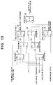
- Fig. 10 shows a logical system (mixing process system) that performs the mixing operation.
- the logical system comprises selectors 20 and 21, dividing devices 22 and 23, a subtracting device 24, multiplying devices 25 and 26, and an adding device 27.
- the mixing ratio in the case that the sub image data is “1” is substantially different from the mixing ratio in the case that the sub image data is "0".
- the sub image data is "1” the sub image contrast is used as a substantial mixing ratio.
- the sub image data is "0”, "00H” is used as a substantial mixing ratio.
- the sub image can be faded in and out.
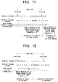
- the parameters (SPCDST and SPCDEN) for the sub image display start timing/display end (clear) timing control the display intervals of sub images.
- the parameter (SPCDST) for the sub image display start timing control starts the display of the sub image display data at a frame number represented by a frame counter.
- the display count of the sub image counts from frame "3" at an I picture output frame and continues counting (incrementing) up to frame "30" that is two frames before the next I picture.
- the sub image that is displayed at the frame number of the frame count is continuously displayed until the next sub image display start point takes place or the sub image is cleared by the sub image clear timing data.
- the sub image display timing data starts with frame “6" and ends with frame "4", the first sub image is displayed while the display frame count counts from frame “6" to frame "4".
- the sub image display data is cleared at the assigned frame number of the frame count corresponding to the sub image clear timing data.
- the sub image display data is cleared at the frame "28".
- Fig. 13 shows the relation between a display data order and display positions thereof.
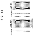
- Fig. 14 is a schematic diagram showing an example of the relation between sub image display data and a display image in frame mode A (non-interlace mode).
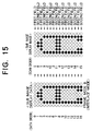
- Fig. 15 is a schematic diagram showing an example of the relation between sub image display data and a display image in frame mode B (interlace mode).
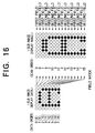
- Fig. 16 is a schematic diagram showing an example of the relation between sub image display data and a display image in field mode.
- sub image display data is displayed from left to right of display pixels and from top to down of display lines of the display region.
- the display method and record method of the sub image display data can be categorized as frame mode (shown in Figs. 14 and 16) and field mode (shown in Fig. 16).
- the record mode of the sub image display data is also recorded.
- the reproducing system displays data, it detects the record mode and controls the display mode.
- the data order of the sub image display data accords with the scan order of the display image.
- the frame mode B interlace mode
- the data order of the sub image display data does not accord with the scan order of the display image
- the data amount of the sub image display data accords with the data amount of the display image.
- the data amount in the field mode is half the data amount in the frame mode.
- sub image control data 30 is composed of a sub image control data header 31 and frame control data 32.
- display frame control data start addresses (CDADRF 1 to 30) 33 are present corresponding to frames of the main image 1.
- the frame display control data 34 are present corresponding to display frames.
- the display frame control data start addresses (CDADRF 1 to 30) 33 represent relative positions from the beginning of the sub image control data header 31 of frame control data.
- the display frame control data start addresses (CDADRF 1 to 30) 33 control the sub image display, frame by frame.
- the sub image reproducing system generates the start address of the frame control data corresponding to the display frame control data start address 33 of a frame number to be controlled. With the start address, the sub image reproducing system accesses the frame control data.
- the display frame control data start address 33 represents the start position of each frame control data that is the number of relative bytes from the sub image control data header.
- CDADRF 1 represents the start position of the control data of frame 1.
- CDADRF 2 represents the start position of the control data of frame 2. And so on.
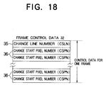
- Fig. 18 shows a structure of frame control data.
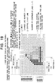
- Fig. 19 shows an example of a sub image display pattern.
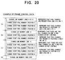
- Fig. 20 shows an example of frame control data.
- the frame control data 32 for one frame is composed of a change line number 35 and change start pixel numbers 36.
- the change line number 35 represents from what line of a display frame the contour corresponding color, the sub image color, and the contrast are controlled, how many times they are changed on the line, and how many lines they are changed.
- the change line number 35 is represented as a bit structure such as [b31 Reserved b28], [b27 Change line number b16], [b15 Number of pixel change points b12], and [b11 Number of continuous lines b0].
- the change start pixel number 36 represents a pixel position at which the contour compensating color, the sub image color, and the contrast are changed and a contour compensating color, a sub pixel color, and a contrast that have been changed.
- the change start pixel numbers continue for the number of change points corresponding to the change line number.
- the change start pixel number is represented as a bit structure such as [b31 Reserved b28], [b27 Change pixel number b16], [b15 Sub image color after change b12], [b11 Contour compensating color after change b8], and [b7 Contrast ratio after change b0].
- the sub image display pattern is represented by a combination of the change line number 35 and the change start pixel numbers 36.
- the number of pixel change points, position, sub image color, contour compensating color, and contrast ratio on line “12" are different from those on line "14". Thus, for each line, a change line number and a change start pixel number should be formed.
- the number of change continuous lines of each of change line numbers "12" and “14" is "0" because there are no continuous lines.
- a change line number 35 that is defined by a predetermined pattern and that follows the last change start pixel number 36 is formed so that a change start pixel number 36 on a continuous line represents the end of the data structure.
- the predetermined pattern of the end code is for example a bit structure "FFFF0000H" (hexadecimal notation).
- the change line number 35 is represented in binary notation as follows (see Fig. 21). "00000000000011000010101011111111”.
- Fig. 22 shows changes of sub image colors, contour compensating colors, and contrast ratios.
- the pixel change points are present at positions C, B, and A in line direction.
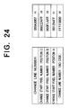
- the pixel change start point at position C is represented corresponding to the example of bit structure. Since position C is present at dot 12 from the left edge of the line, the change pixel number is "12".
- the sub image color, the contour compensating color, and the contrast ratio that are present on the right of position C are "2H", "AH", and "FFH", respectively.
- the change start pixel number at position C is represented in binary notation as follows (see Fig. 23). "00000000000001000011000000000111”.
- Position B is present at dot 15 and only the sub image color changes from “2H” to “1H".
- the change start pixel number at position B can be represented in hexadecimal notation as follows.
- C2 is changed to "F1”.
- Position A is present at dot 18 and the sub image color and contour compensating color change to "5H” and "4H", respectively.
- the change start pixel number at position A can be represented in hexadecimal notation as follows.
- Fig. 25 is a block diagram showing the sub image process system.
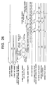
- Fig. 26 is a timing chart of a process for the frame control data.
- the sub image process system comprises a change line number data register 50, a line counter 51, comparators 52 and 53, a change start pixel data read cycle control portion 54, a change start pixel number data register 55, a change pixel number register 56, a dot counter 57, a register read control portion 58, a sub image color register 59, a contour compensating color register 60, and a contrast ratio register 61.
- the change line number data register 50 holds a change line number corresponding to frame control data.
- the line counter 51 counts a line number.
- the comparator 52 compares a change line number with a line count value. When they match, the comparator 52 outputs a match signal.
- the change start pixel data read cycle control portion 54 receives the number of pixel change points, the match signal (received from the comparator 52), a horizontal (H) blanking signal, and so forth and controls the holding timing of the change start pixel number data.
- the change start pixel number data register 55 holds position data at the control timing of the change start pixel data read cycle control portion 54.
- the change pixel number register 56 holds a change pixel number.
- the comparator 53 compares the count value of the dot counter 57 with the value of the change pixel number register. When they match, the comparator 53 outputs a match signal to the register read control portion 58.
- the register read control portion 58 control the data hold timing of each of the sub image color register 59, the contour compensating color register 60, and the contrast ratio register 61 corresponding to the match signal received from the comparator 53.
- the frame control data is processed as follows.
- the comparator 52 when the line count number counted by the line counter 51 of the display portion matches the change line number in the change line number data of the frame control data, the comparator 52 outputs the match signal to the change start pixel data read cycle control portion 54.
- the change start pixel data read cycle control portion 54 starts the read cycle.
- the change start pixel data read cycle control portion 54 stores change start pixel numbers necessary for changing pixels on a line to a process portion (namely, each change start pixel number data register 55) in the first horizontal (H) blanking interval. Alternatively, the change start pixel data read cycle control portion 54 stores the change start pixel numbers to each change start pixel number data register 55 until change line number data that represents end code takes place.
- the horizonal dot counter 57 is incremented by "1" for the line.
- the register read control portion 58 holds a sub image color, a contour compensating color, and a contrast ratio that have been changed in the process portion (namely, the sub image color register 59, the contour compensating color register 60, and the contrast ratio register 61).
- the data held in the sub image color register 59, the contour compensating color register 60, and the contrast ratio register 61 are used as sub image display control data until next pixel change point takes place.
- the sub image process system performs the above-described operation whenever it scans each line, when the number of continuous lines in the change line number is other than "0", after the count line number matches the change line number of the change line number data, while the lines corresponding to the number of continuous lines are being scanned, the same change start pixel number data is read and the same sub image display control is repeated.
- the sub image data packet system since data that assigning a display region of a sub image is provided and other than the display region is not displayed, display spatial loss of which all data for one frame is transmitted to the display portion can be remarkably reduced.
- display spatial loss of which all data for one frame is transmitted to the display portion can be remarkably reduced.
- only information of shapes of sub images to be displayed are sub image display data.
- color information data, contour color data, and contrast data (these data are referred to as color information) that are required for each pixel can be reduced.
- the sub image display data is bit map data, the shapes of sub images can be freely displayed.
- Default values are assigned for the color information of sub images.
- new color information is assigned.
- the color information that is reassigned is formed as a packet of frame control data independent from sub image display data.
- the position of the frame control data can be assigned, pixel by pixel.
- the sub image color can be controlled with the same accuracy as the conventional bit map data system. Since most color information of a normal sub image does not change, pixel by pixel, the color information is not assigned, pixel by pixel. Thus, the color information data (frame control data) can be remarkably reduced.
- the sub image display data is continuously output from the display portion in a plurality of frame intervals unless the shape of the sub image changes. In these intervals, the color of the sub image is controlled by frame control data in the same sub image packet. Thus, it is not necessary to continuously supply the complete bit map data even if color information partly changes. Thus, display temporal loss of the sub image data can be remarkably reduced.
- the display position, the display size, and the display color of the sub image data can change for each display unit of the main image.
- losses in data transmission and display control can be reduced.
- the sub image can be freely displayed by the bit map data system.
- information that assigns a display region of the sub image is provided so that data other than the region is not transmitted and displayed.
- the assigned display region only information of shapes of sub images to be displayed is treated as display data.
- the display color, the contour compensating color, and the sub image contrast that are required for each pixel are formed in a header portion.
- the amount of data to be transmitted can be reduced. Since the display data portion is bit map data, the shapes of sub images can be freely displayed.
- Default values are assigned for the color information of sub images.
- new color information is assigned.
- the color information that is reassigned is formed as a packet of frame control data independent from sub image display data.
- the position of the frame control data can be assigned, pixel by pixel.
- the sub image color can be controlled with the same accuracy as the conventional bit map data system. Since most color information of a normal sub image does not change, pixel by pixel, the color information is not assigned, pixel by pixel. Thus, the color information data (frame control data) can be remarkably reduced.
- the sub image display data is continuously output from the display portion in a plurality of frame intervals unless the shape of the sub image changes. In these intervals, the color of the sub image is controlled by frame control data in the same sub image packet. Thus, it is not necessary to continuously supply the complete bit map data even if color information partly changes. Thus, display temporal loss of the sub image data can be remarkably reduced.
Landscapes
- Engineering & Computer Science (AREA)
- Multimedia (AREA)
- Signal Processing (AREA)
- Computer Graphics (AREA)
- Television Signal Processing For Recording (AREA)
- Controls And Circuits For Display Device (AREA)
- Studio Circuits (AREA)
Applications Claiming Priority (3)
| Application Number | Priority Date | Filing Date | Title |
|---|---|---|---|
| JP6076193A JP2931755B2 (ja) | 1994-04-14 | 1994-04-14 | データ再生装置、データエンコード装置、データエンコード方法及びデータ再生システム |
| JP7619394 | 1994-04-14 | ||
| JP76193/94 | 1994-04-14 |
Publications (3)
| Publication Number | Publication Date |
|---|---|
| EP0677954A2 true EP0677954A2 (fr) | 1995-10-18 |
| EP0677954A3 EP0677954A3 (fr) | 1998-01-28 |
| EP0677954B1 EP0677954B1 (fr) | 2003-06-11 |
Family
ID=13598309
Family Applications (1)
| Application Number | Title | Priority Date | Filing Date |
|---|---|---|---|
| EP95302498A Expired - Lifetime EP0677954B1 (fr) | 1994-04-14 | 1995-04-13 | Procédé pour constituer un paquet de données d'une sous-image comportant des données d'une sous-image superdosé sur une image principale, milieu d'enregistrement pour enregistrer le paquet de données de la sous-image et dispositif de traitement d'image |
Country Status (5)
| Country | Link |
|---|---|
| US (1) | US5999160A (fr) |
| EP (1) | EP0677954B1 (fr) |
| JP (1) | JP2931755B2 (fr) |
| KR (1) | KR0160189B1 (fr) |
| DE (1) | DE69531021T2 (fr) |
Cited By (6)
| Publication number | Priority date | Publication date | Assignee | Title |
|---|---|---|---|---|
| GB2346498A (en) * | 1996-04-12 | 2000-08-09 | Pandora Int Ltd | Image processing |
| US6344853B1 (en) | 2000-01-06 | 2002-02-05 | Alcone Marketing Group | Method and apparatus for selecting, modifying and superimposing one image on another |
| WO2004032122A1 (fr) | 2002-10-02 | 2004-04-15 | Lg Electronics Inc. | Support d'enregistrement presentant une structure de donnees pour la gestion de reproduction de donnees graphiques et procedes et appareils d'enregistrement et de reproduction |
| US7616865B2 (en) | 2003-04-30 | 2009-11-10 | Lg Electronics Inc. | Recording medium having a data structure for managing reproduction of subtitle data and methods and apparatuses of recording and reproducing |
| US7769275B2 (en) | 2002-10-04 | 2010-08-03 | Lg Electronics, Inc. | Recording medium having a data structure for managing reproduction of graphic data and recording and reproducing methods and apparatuses |
| EP2674805A3 (fr) * | 2012-06-13 | 2017-04-19 | Robert Hilkes | Appareil et procédé permettant d'améliorer la performance visuelle humaine dans un système vidéo de type casque |
Families Citing this family (35)
| Publication number | Priority date | Publication date | Assignee | Title |
|---|---|---|---|---|
| US7738015B2 (en) | 1997-10-09 | 2010-06-15 | Fotonation Vision Limited | Red-eye filter method and apparatus |
| US7630006B2 (en) | 1997-10-09 | 2009-12-08 | Fotonation Ireland Limited | Detecting red eye filter and apparatus using meta-data |
| US7042505B1 (en) | 1997-10-09 | 2006-05-09 | Fotonation Ireland Ltd. | Red-eye filter method and apparatus |
| KR100448452B1 (ko) | 2000-06-09 | 2004-09-13 | 엘지전자 주식회사 | 고밀도 광 기록매체의 메뉴 지원방법 |
| FI20002852A7 (fi) * | 2000-12-22 | 2002-06-23 | Nokia Corp | Objektien siirto meneillään olevan tiedonsiirtotoimenpiteen sisällä |
| EP1618562A4 (fr) * | 2003-04-29 | 2011-03-16 | Lg Electronics Inc | Support d'enregistrement dote d'une structure de donnees permettant de gerer la reproduction de donnees graphiques, procedes et appareils d'enregistrement et de reproduction associes |
| US7970182B2 (en) | 2005-11-18 | 2011-06-28 | Tessera Technologies Ireland Limited | Two stage detection for photographic eye artifacts |
| US8036458B2 (en) | 2007-11-08 | 2011-10-11 | DigitalOptics Corporation Europe Limited | Detecting redeye defects in digital images |
| US8254674B2 (en) | 2004-10-28 | 2012-08-28 | DigitalOptics Corporation Europe Limited | Analyzing partial face regions for red-eye detection in acquired digital images |
| US7792970B2 (en) | 2005-06-17 | 2010-09-07 | Fotonation Vision Limited | Method for establishing a paired connection between media devices |
| US8170294B2 (en) | 2006-11-10 | 2012-05-01 | DigitalOptics Corporation Europe Limited | Method of detecting redeye in a digital image |
| US7920723B2 (en) | 2005-11-18 | 2011-04-05 | Tessera Technologies Ireland Limited | Two stage detection for photographic eye artifacts |
| US7689009B2 (en) | 2005-11-18 | 2010-03-30 | Fotonation Vision Ltd. | Two stage detection for photographic eye artifacts |
| US7574016B2 (en) | 2003-06-26 | 2009-08-11 | Fotonation Vision Limited | Digital image processing using face detection information |
| KR20050005074A (ko) * | 2003-07-01 | 2005-01-13 | 엘지전자 주식회사 | 고밀도 광디스크의 그래픽 데이터 관리방법 및 그에 따른고밀도 광디스크 |
| KR20050004339A (ko) * | 2003-07-02 | 2005-01-12 | 엘지전자 주식회사 | 고밀도 광디스크의 그래픽 데이터 관리방법 및 그에 따른고밀도 광디스크 |
| WO2005004478A1 (fr) * | 2003-07-03 | 2005-01-13 | Matsushita Electric Industrial Co., Ltd. | Support d'enregistrement, appareil de reproduction, procede d'enregistrement, circuit integre, programme et procede de reproduction |
| DE10330329A1 (de) * | 2003-07-04 | 2005-02-17 | Micronas Gmbh | Verfahren zur Darstellung von Teletextseiten auf einer Anzeigevorrichtung |
| US9412007B2 (en) | 2003-08-05 | 2016-08-09 | Fotonation Limited | Partial face detector red-eye filter method and apparatus |
| US8520093B2 (en) | 2003-08-05 | 2013-08-27 | DigitalOptics Corporation Europe Limited | Face tracker and partial face tracker for red-eye filter method and apparatus |
| KR20050064150A (ko) * | 2003-12-23 | 2005-06-29 | 엘지전자 주식회사 | 고밀도 광디스크의 메뉴 구성방법 및 실행방법과기록재생장치 |
| JP4539122B2 (ja) * | 2004-03-01 | 2010-09-08 | 株式会社日立製作所 | 再生装置、再生方法、記録方法 |
| JP4498205B2 (ja) * | 2004-05-06 | 2010-07-07 | キヤノン株式会社 | 表示装置 |
| JP4749701B2 (ja) * | 2004-11-18 | 2011-08-17 | 富士フイルム株式会社 | オンスクリーンディスプレイ装置 |
| US7599577B2 (en) | 2005-11-18 | 2009-10-06 | Fotonation Vision Limited | Method and apparatus of correcting hybrid flash artifacts in digital images |
| JP4754364B2 (ja) * | 2006-01-20 | 2011-08-24 | 三菱電機株式会社 | 画像重ね合わせ装置 |
| EP1987475A4 (fr) | 2006-02-14 | 2009-04-22 | Fotonation Vision Ltd | Detection et correction automatiques de defauts de flash anti-yeux rouges |
| US7965875B2 (en) | 2006-06-12 | 2011-06-21 | Tessera Technologies Ireland Limited | Advances in extending the AAM techniques from grayscale to color images |
| TW200814747A (en) * | 2006-09-08 | 2008-03-16 | Benq Corp | Image processing methods and systems, and machine readable medium thereof |
| US8055067B2 (en) | 2007-01-18 | 2011-11-08 | DigitalOptics Corporation Europe Limited | Color segmentation |
| US7995804B2 (en) | 2007-03-05 | 2011-08-09 | Tessera Technologies Ireland Limited | Red eye false positive filtering using face location and orientation |
| US8503818B2 (en) | 2007-09-25 | 2013-08-06 | DigitalOptics Corporation Europe Limited | Eye defect detection in international standards organization images |
| JP5002447B2 (ja) * | 2007-12-27 | 2012-08-15 | 株式会社東芝 | 映像音声再生装置 |
| US8212864B2 (en) | 2008-01-30 | 2012-07-03 | DigitalOptics Corporation Europe Limited | Methods and apparatuses for using image acquisition data to detect and correct image defects |
| US8081254B2 (en) | 2008-08-14 | 2011-12-20 | DigitalOptics Corporation Europe Limited | In-camera based method of detecting defect eye with high accuracy |
Family Cites Families (20)
| Publication number | Priority date | Publication date | Assignee | Title |
|---|---|---|---|---|
| JPS5768982A (en) * | 1980-10-16 | 1982-04-27 | Sony Corp | Display device |
| IE852259L (en) * | 1985-09-13 | 1987-03-13 | Scottish & Newcastle Breweries | A method and apparatus for constructing, storing and¹displaying characters |
| US5210851A (en) * | 1988-01-08 | 1993-05-11 | Hewlett-Packard Company | High capacity tape drive transparently writes and reads large packets of blocked data between interblock gaps |
| JPH02152382A (ja) * | 1988-12-02 | 1990-06-12 | Matsushita Electric Ind Co Ltd | 文字放送受信装置 |
| JP2531795B2 (ja) * | 1989-06-29 | 1996-09-04 | パイオニア株式会社 | 画像情報再生装置 |
| US5164711A (en) * | 1990-02-08 | 1992-11-17 | International Business Machines Corporation | System and method for generating graphical output |
| US5544176A (en) * | 1990-02-13 | 1996-08-06 | Canon Kabushiki Kaisha | Information recording apparatus which eliminates unnecessary data before recording |
| US5260783A (en) * | 1991-02-21 | 1993-11-09 | Gte Laboratories Incorporated | Layered DCT video coder for packet switched ATM networks |
| US5294982A (en) * | 1991-12-24 | 1994-03-15 | National Captioning Institute, Inc. | Method and apparatus for providing dual language captioning of a television program |
| KR0165246B1 (ko) * | 1992-09-04 | 1999-03-20 | 윤종용 | 문자입력 예약녹화 방법 및 장치 |
| JP2785220B2 (ja) * | 1992-09-22 | 1998-08-13 | ソニー株式会社 | データ符号化装置および方法、並びにデータ復号化装置および方法 |
| JP3264290B2 (ja) * | 1992-09-22 | 2002-03-11 | ソニー株式会社 | 復号方法および復号装置 |
| JPH06121263A (ja) * | 1992-10-08 | 1994-04-28 | Sony Corp | 映像信号の記録方法 |
| JP3630441B2 (ja) * | 1992-12-21 | 2005-03-16 | ソニー株式会社 | 送信方法、受信方法、通信方法、双方向バスシステム及び電子機器 |
| US5521712A (en) * | 1993-02-12 | 1996-05-28 | Sony Corporation | Teletext signal recording and reproducing apparatus |
| EP0662770B1 (fr) * | 1993-06-30 | 2003-05-14 | Sony Corporation | Appareil et procede de codage/decodage de donnees de sous-titres |
| JPH0787444A (ja) * | 1993-07-16 | 1995-03-31 | Pioneer Electron Corp | 圧縮符号化データ記録方法 |
| US5684542A (en) * | 1993-12-21 | 1997-11-04 | Sony Corporation | Video subtitle processing system |
| US5446491A (en) * | 1993-12-21 | 1995-08-29 | Hitachi, Ltd. | Multi-point video conference system wherein each terminal comprises a shared frame memory to store information from other terminals |
| US5526050A (en) * | 1994-03-31 | 1996-06-11 | Cognex Corporation | Methods and apparatus for concurrently acquiring video data from multiple video data sources |
-
1994
- 1994-04-14 JP JP6076193A patent/JP2931755B2/ja not_active Expired - Lifetime
-
1995
- 1995-04-13 DE DE69531021T patent/DE69531021T2/de not_active Expired - Lifetime
- 1995-04-13 US US08/421,182 patent/US5999160A/en not_active Expired - Lifetime
- 1995-04-13 EP EP95302498A patent/EP0677954B1/fr not_active Expired - Lifetime
- 1995-04-14 KR KR1019950008747A patent/KR0160189B1/ko not_active Expired - Lifetime
Cited By (9)
| Publication number | Priority date | Publication date | Assignee | Title |
|---|---|---|---|---|
| GB2346498A (en) * | 1996-04-12 | 2000-08-09 | Pandora Int Ltd | Image processing |
| GB2346498B (en) * | 1996-04-12 | 2000-09-13 | Pandora Int Ltd | Image processing |
| US6344853B1 (en) | 2000-01-06 | 2002-02-05 | Alcone Marketing Group | Method and apparatus for selecting, modifying and superimposing one image on another |
| WO2004032122A1 (fr) | 2002-10-02 | 2004-04-15 | Lg Electronics Inc. | Support d'enregistrement presentant une structure de donnees pour la gestion de reproduction de donnees graphiques et procedes et appareils d'enregistrement et de reproduction |
| EP1547067A4 (fr) * | 2002-10-02 | 2009-06-24 | Lg Electronics Inc | Support d'enregistrement presentant une structure de donnees pour la gestion de reproduction de donnees graphiques et procedes et appareils d'enregistrement et de reproduction |
| US7809250B2 (en) | 2002-10-02 | 2010-10-05 | Lg Electronics Inc. | Recording medium having a data structure for managing reproduction of graphic data and recording and reproducing methods and apparatuses |
| US7769275B2 (en) | 2002-10-04 | 2010-08-03 | Lg Electronics, Inc. | Recording medium having a data structure for managing reproduction of graphic data and recording and reproducing methods and apparatuses |
| US7616865B2 (en) | 2003-04-30 | 2009-11-10 | Lg Electronics Inc. | Recording medium having a data structure for managing reproduction of subtitle data and methods and apparatuses of recording and reproducing |
| EP2674805A3 (fr) * | 2012-06-13 | 2017-04-19 | Robert Hilkes | Appareil et procédé permettant d'améliorer la performance visuelle humaine dans un système vidéo de type casque |
Also Published As
| Publication number | Publication date |
|---|---|
| DE69531021D1 (de) | 2003-07-17 |
| EP0677954A3 (fr) | 1998-01-28 |
| DE69531021T2 (de) | 2004-05-06 |
| US5999160A (en) | 1999-12-07 |
| KR950030058A (ko) | 1995-11-24 |
| EP0677954B1 (fr) | 2003-06-11 |
| JP2931755B2 (ja) | 1999-08-09 |
| JPH07288776A (ja) | 1995-10-31 |
| KR0160189B1 (ko) | 1999-01-15 |
Similar Documents
| Publication | Publication Date | Title |
|---|---|---|
| EP0677954B1 (fr) | Procédé pour constituer un paquet de données d'une sous-image comportant des données d'une sous-image superdosé sur une image principale, milieu d'enregistrement pour enregistrer le paquet de données de la sous-image et dispositif de traitement d'image | |
| US4496976A (en) | Reduced memory graphics-to-raster scan converter | |
| US5553165A (en) | Parallel error diffusion method and apparatus | |
| KR100362071B1 (ko) | 단일 프레임 버퍼 영상 처리 시스템 | |
| US5559954A (en) | Method & apparatus for displaying pixels from a multi-format frame buffer | |
| US5257348A (en) | Apparatus for storing data both video and graphics signals in a single frame buffer | |
| US4814756A (en) | Video display control system having improved storage of alphanumeric and graphic display data | |
| JPH08202318A (ja) | 記憶性を有する表示装置の表示制御方法及びその表示システム | |
| US5663772A (en) | Gray-level image processing with weighting factors to reduce flicker | |
| JPS6250872B2 (fr) | ||
| KR100312392B1 (ko) | 디지탈텔레비젼용유니트 | |
| US5051929A (en) | Electronic memory state reallocation system for improving the resolution of color coding video systems | |
| KR920004118B1 (ko) | 문자다중방송 수신장치 | |
| EP0246276A1 (fr) | Entrelacement programmable avec amelioration du saut et du contraste dans des systemes de visualisation a longue persistance | |
| KR0163173B1 (ko) | 화상판독장치 | |
| CA2105131C (fr) | Appareil de traitement d'images | |
| US5404177A (en) | Double-picture type television receiver | |
| US5835103A (en) | Apparatus using memory control tables related to video graphics processing for TV receivers | |
| JP3560657B2 (ja) | デジタルテレビ受像機用グラフィックデータユニットおよびデジタルテレビ受像機を使用する方法 | |
| CA1256553A (fr) | Systeme de transmission numerique | |
| US20070263977A1 (en) | Image processing apparatus | |
| JP2004061654A (ja) | キャラクタ表示制御装置 | |
| JPH05145906A (ja) | 表示メモリ制御装置 | |
| JPH07281626A (ja) | インターレース表示装置 | |
| JPH0237389A (ja) | 階調表示制御装置 |
Legal Events
| Date | Code | Title | Description |
|---|---|---|---|
| PUAI | Public reference made under article 153(3) epc to a published international application that has entered the european phase |
Free format text: ORIGINAL CODE: 0009012 |
|
| 17P | Request for examination filed |
Effective date: 19950511 |
|
| AK | Designated contracting states |
Kind code of ref document: A2 Designated state(s): DE FR GB NL |
|
| PUAL | Search report despatched |
Free format text: ORIGINAL CODE: 0009013 |
|
| AK | Designated contracting states |
Kind code of ref document: A3 Designated state(s): DE FR GB NL |
|
| 17Q | First examination report despatched |
Effective date: 20000725 |
|
| GRAH | Despatch of communication of intention to grant a patent |
Free format text: ORIGINAL CODE: EPIDOS IGRA |
|
| GRAH | Despatch of communication of intention to grant a patent |
Free format text: ORIGINAL CODE: EPIDOS IGRA |
|
| GRAA | (expected) grant |
Free format text: ORIGINAL CODE: 0009210 |
|
| AK | Designated contracting states |
Designated state(s): DE FR GB NL |
|
| REG | Reference to a national code |
Ref country code: GB Ref legal event code: FG4D |
|
| REF | Corresponds to: |
Ref document number: 69531021 Country of ref document: DE Date of ref document: 20030717 Kind code of ref document: P |
|
| ET | Fr: translation filed | ||
| PLBE | No opposition filed within time limit |
Free format text: ORIGINAL CODE: 0009261 |
|
| STAA | Information on the status of an ep patent application or granted ep patent |
Free format text: STATUS: NO OPPOSITION FILED WITHIN TIME LIMIT |
|
| 26N | No opposition filed |
Effective date: 20040312 |
|
| PGFP | Annual fee paid to national office [announced via postgrant information from national office to epo] |
Ref country code: GB Payment date: 20140409 Year of fee payment: 20 |
|
| PGFP | Annual fee paid to national office [announced via postgrant information from national office to epo] |
Ref country code: DE Payment date: 20140430 Year of fee payment: 20 Ref country code: FR Payment date: 20140409 Year of fee payment: 20 Ref country code: NL Payment date: 20140410 Year of fee payment: 20 |
|
| REG | Reference to a national code |
Ref country code: DE Ref legal event code: R071 Ref document number: 69531021 Country of ref document: DE |
|
| REG | Reference to a national code |
Ref country code: DE Ref legal event code: R071 Ref document number: 69531021 Country of ref document: DE |
|
| REG | Reference to a national code |
Ref country code: GB Ref legal event code: PE20 Expiry date: 20150412 |
|
| PG25 | Lapsed in a contracting state [announced via postgrant information from national office to epo] |
Ref country code: GB Free format text: LAPSE BECAUSE OF EXPIRATION OF PROTECTION Effective date: 20150412 |