EP0678190B1 - Gehäusemontierte Auslesesignalverarbeitungsanlage für verbesserte Leistung bei niedriger Drehrate - Google Patents
Gehäusemontierte Auslesesignalverarbeitungsanlage für verbesserte Leistung bei niedriger Drehrate Download PDFInfo
- Publication number
- EP0678190B1 EP0678190B1 EP94907144A EP94907144A EP0678190B1 EP 0678190 B1 EP0678190 B1 EP 0678190B1 EP 94907144 A EP94907144 A EP 94907144A EP 94907144 A EP94907144 A EP 94907144A EP 0678190 B1 EP0678190 B1 EP 0678190B1
- Authority
- EP
- European Patent Office
- Prior art keywords
- optical signal
- optical
- sensor
- readout
- signal
- Prior art date
- Legal status (The legal status is an assumption and is not a legal conclusion. Google has not performed a legal analysis and makes no representation as to the accuracy of the status listed.)
- Expired - Lifetime
Links
- 230000004048 modification Effects 0.000 title description 2
- 238000012986 modification Methods 0.000 title description 2
- 230000003287 optical effect Effects 0.000 claims abstract description 103
- 230000001902 propagating effect Effects 0.000 claims description 11
- 230000010355 oscillation Effects 0.000 claims description 5
- 230000008878 coupling Effects 0.000 description 6
- 238000010168 coupling process Methods 0.000 description 6
- 238000005859 coupling reaction Methods 0.000 description 6
- 230000000694 effects Effects 0.000 description 6
- 238000010586 diagram Methods 0.000 description 5
- 230000008859 change Effects 0.000 description 4
- 230000000116 mitigating effect Effects 0.000 description 2
- 230000005540 biological transmission Effects 0.000 description 1
- 238000001514 detection method Methods 0.000 description 1
- 230000001627 detrimental effect Effects 0.000 description 1
- 230000006872 improvement Effects 0.000 description 1
- 238000002789 length control Methods 0.000 description 1
- 230000003534 oscillatory effect Effects 0.000 description 1
- 230000035945 sensitivity Effects 0.000 description 1
Images


Classifications
-
- G—PHYSICS
- G01—MEASURING; TESTING
- G01C—MEASURING DISTANCES, LEVELS OR BEARINGS; SURVEYING; NAVIGATION; GYROSCOPIC INSTRUMENTS; PHOTOGRAMMETRY OR VIDEOGRAMMETRY
- G01C19/00—Gyroscopes; Turn-sensitive devices using vibrating masses; Turn-sensitive devices without moving masses; Measuring angular rate using gyroscopic effects
- G01C19/58—Turn-sensitive devices without moving masses
- G01C19/64—Gyrometers using the Sagnac effect, i.e. rotation-induced shifts between counter-rotating electromagnetic beams
- G01C19/66—Ring laser gyrometers
- G01C19/661—Ring laser gyrometers details
- G01C19/662—Ring laser gyrometers details signal readout; dither compensators
-
- H—ELECTRICITY
- H01—ELECTRIC ELEMENTS
- H01S—DEVICES USING THE PROCESS OF LIGHT AMPLIFICATION BY STIMULATED EMISSION OF RADIATION [LASER] TO AMPLIFY OR GENERATE LIGHT; DEVICES USING STIMULATED EMISSION OF ELECTROMAGNETIC RADIATION IN WAVE RANGES OTHER THAN OPTICAL
- H01S3/00—Lasers, i.e. devices using stimulated emission of electromagnetic radiation in the infrared, visible or ultraviolet wave range
- H01S3/05—Construction or shape of optical resonators; Accommodation of active medium therein; Shape of active medium
- H01S3/08—Construction or shape of optical resonators or components thereof
- H01S3/081—Construction or shape of optical resonators or components thereof comprising three or more reflectors
- H01S3/083—Ring lasers
Definitions
- the present invention relates to readout devices for use in ring laser angular rate sensors. Specifically, the present invention provides a readout device that displays improved performance at low input rates by eliminating scatter sources.
- Ring laser angular rate sensors or ring laser gyroscopes are fairly well known in the field of angular rate sensing. Examples of ring laser gyroscopes are shown in U.S. Patent 3,373,650 which is assigned to the assignee of the present invention.
- two counter propagating light beams are maintained within a closed loop path to form a rotation sensing device. Rotation of this device around an axis which is normal to a plane containing the closed loop path causes the relative path lengths in either direction to change. Detections of these changes in path length can be used to measure the rate of rotation.
- Backscattering occurs when the optical signal propagating in one direction within the ring laser gyro is scattered back into the gyro but in the opposite direction. Backscattering can be due to sources within the laser cavity or sources outside the laser cavity. Since it is desirable that the optical signals within the ring laser gyro oscillate independently at their particular frequencies, backscatter is detrimental as it causes an unwanted coupling influence between the two optical signals.
- the angular rate sensor is rotationally oscillated or dithered. If the readout signal is averaged over a period of time the average rotation rate of the oscillation signal is zero. Therefore this oscillation or dither will not affect the sensitivity of the gyro.
- the dither signal or rotational oscillation of the ring laser gyroscope can be removed from the output signal by either geometrically eliminating the effects of this oscillation or electronically removing the dither signal. To eliminate the dithering geometrically the optical elements making up the readout must be appropriately placed. Once appropriately placed the change in path length due to dithering is canceled out by the scale factor of the gyroscope.
- Numerous readouts are traditionally placed on the ring laser angular rate sensor to perform numerous other functions.
- An example of these functions are laser intensity sensing to assure the optical signals within the ring laser angular rate sensor are resonating at a sufficiently strong level.
- Gyro dither is effective in mitigating the effect of scatter sources that oscillate along with the gyro block; however, dither is not effective in mitigating the effects of case mounted components.
- There are numerous sources of back scattering including the readout optics used, optical sensors attached to the laser gyro or the gyro case, and even the laser gyro case itself.
- a laser block 10 contains a number of tunnels or bores 12 which create a closed loop path within laser block 10. Bores 12 carry the optical signals which make up the angular rate sensor.
- an output mirror 14 which is partially reflective and partially transmissive. Output mirror 14 allows a portion of the optical signals within laser block 10 to be transmitted through output mirror 14 while another portion of the optical signals is reflected back into the adjoining bore 12. Shown as lines on Fig. 1 are a counter clockwise signal or CCW signal 20 and a clockwise signal or CW signal 22. While Fig.
- CCW signal 20 is transmitted through output mirror 14 and toward a corner cube 16 which is mounted to the gyro case (not shown). Corner cube 16 causes CCW signal 20 to be translated and reflected back towards output mirror 14. Upon meeting an upper surface 24 of output mirror 14 CCW signal 20 is reflected off surface 24 and directed onto an optical sensor 18. Meanwhile, CW signal 22 is transmitted through output mirror 14 and directly onto optical sensor 18. Optical sensor 18 receives a combination of CCW signal 20 and CW signal 22. Those skilled in the art will recognize that this combination of these two signals can be used to detect rotation.
- the readout of the present invention uses a case mounted type readout whereby the optical sensors, and the corner cube are mounted to the case. Having these optical elements mounted to the case allows the gyro block to dither separate from the aforementioned optical elements. By configuring the elements in this way, the effects of dithering upon the gyro output are removed through geometry.
- the surface of all optical elements are tilted so they are not normal to their respective incoming optical signal.
- the surfaces of the optical elements are further not normal to the gyro lasing plane.
- the tilt of the optical elements reduces the backscattering caused by these elements because any direct reflections will be directed out of the lasing plane and will not interfere with the counter propagating signals. Furthermore, the indirect reflections traveling back toward the gyro cavity are reduced.
- Gyroscope 50 which operates in accord with the principles of the present invention.
- Gyroscope 50 has a laser block 10 having a polygonal configuration.
- the laser block 10 of the present embodiment is configured in a substantially triangular shape and has a plurality of bores 12 for carrying the optical signals used to detect rotation. Bores 12 extend to connect at each corner of laser block 10.
- corner mirrors 30 Upon two corners of laser block 10 are corner mirrors 30.
- On a third corner of laser block 10 is an output mirror 14.
- Output mirror 14 is a partially reflective mirror allowing a portion of an optical signal to be reflected off of the surface of the mirror while a second portion of the signal is transmitted through output mirror 14.
- Output mirror 14 and corner mirrors 30 are used to cause an optical signal to be reflected around the closed loop path created by bores 12.
- Bores 12 contain an active gas to allow the creation of a gas discharge laser. Lasing is assisted by a pair of anodes 32 and cathode 34. Cathode 32 and anodes 34 are in communication with bores 12 via communication bores 36. By applying an electrical potential between cathode 34 and anodes 32 a gas discharge laser is created within bores 12 creating light beams which travel around the closed loop path created by bores 12.
- the ring laser gyro of the present invention is rotationally oscillated or dithered. This dithering is done by a dither means 38 which causes laser block 10 to be rotationally oscillated about its central axis.
- Dither means 38 causes laser block 10 to be rotationally oscillated with respect to case 40.
- Dither means 38 comprises a central hub member 80, a plurality of spokes 82, a plurality of piezoelectric elements 86 and an outer rim member 84. Piezoelectric elements 86 are excited by an oscillatory signal and cause outer rim 84 to oscillate with respect to central post 80. Since central post 80 is attached to case 40, block 10 is caused to oscillate with respect to case 40.
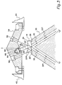
- Fig. 3 there is shown an exploded view of one corner of ring laser gyro 50.
- Gyro block 10 is positioned in close proximity to a readout holder 54.
- Readout holder 54 has all the facilities to house corner cube 16, a readout optical sensor 56, and a path length control optical sensor or PLC optical sensor 58.
- Readout holder 54 provides an easy means of positioning and holding all optical elements.
- Readout holder 54 is attached to gyro mounting case 40 so that optical sensors 56, 58 and corner cube 16 are held stationary while gyro block 10 oscillates or dithers.
- readout holder 54 is made out of a machinable plastic to provide ease of manufacturer and reduced cost.
- CCW signal 20 and CW signal 22 it is necessary to combine the two counter propagating optic signals, CCW signal 20 and CW signal 22, to provide a meaningful output indicative of ring laser gyro rotation. This optical combination is achieved through a number of reflections, thus, causing a combined optical signal to be projected upon readout sensor 56.
- CCW optical signal 20 intersects output mirror 14 at an inner surface 26.
- Output mirror 24 is a partially reflective and partially transmissive mirror, thus a portion of CCW signal 20* is reflected back into optical cavity 12 while a second portion 20' of CCW signal 20 is transmitted into output mirror 14.
- Partial CCW optical signal 20' then intersects output mirror upper surface 24 which is a second partially reflective surface.
- a portion 20" of partial CCW signal 20' is transmitted through output mirror upper surface 24 while a second portion 20** is reflected off mirror upper surface 24.
- CCW optical signal 20" is then directed toward corner cube 16.
- Corner cube 16 is a optical prism having an initial surface 62 and three reflective surfaces 64, 66, and 68.
- Portional optical signal 20" intersects with corner cube initial surface 62 and is transmitted therethrough. Subsequently, portional CCW signal 20" intersects first reflecting surface 64 and is directed towards second reflecting surface 66 which then directs portional CCW signal 20" to third reflective surface 68. Upon intersection with third reflective surface 68 portional CCW signal 20" is directed back towards corner cube initial surface 62 and is transmitted therethrough thus directing portional CCW signal 20" back towards output mirror 14. The following is reflection through corner cube initial surface 62 portional CCW signal 20" then intersects with output mirror upper surface 24.
- CW signal 22 also intersects output mirror lower surface 26 where a portion 22' of CW signal 22 is transmitted through output mirror 1ower surface 26 while a second portion 22* is reflected off of output mirror lower surface 26. Following its transmission through output mirror lower surface 26 portional CW signal 22' then intersects output mirror upper surface 24. The point at which proportional CW signal 22' intersects with output mirror upper surface 24 coincides with the point at which portional CCW signal 20" intersects with output mirror upper surface following its reflection from corner cube 16. At this point, portional CCW signs 20" is reflected off of output mirror upper surface 24 while proportional CW signal 22' is transmitted through output mirror upper surface 24.
- These two signals are directed toward readout optical sensor 56. This combination of CW signal 22 and CCW signal 20 when projected upon readout optical sensor 56 provides meaningful data regarding the rotation of ring laser gyro 50.
- portional CCW signal 20 when portional CCW signal 20" intersects output mirror upper surface 24 a portion 20** is reflected back towards output mirror lower surface 26.
- the point at which portional CCW signal 20** intersects with output mirror lower surface 26 is a totally reflective surface thus causing optical signal 20** to be totally reflected back towards output mirror upper surface 24.
- This optical signal is then transmitted through output mirror upper surface 24 and directed towards PLC sensor 58.
- this PLC sensor is used to control the path length of the gyro cavity thus improving its performance.
- readout optical sensor 56 has a planar surface upon which combined CW signal 22 and CCW signal 20 are projected
- PLC sensor 58 has a planar surface upon which CCW signal 20 is projected
- corner cube 16 has an initial surface 62 which is planar. If these surfaces are held normal to the incoming optical signal backscatter can result.
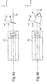
- Fig. 4A there is shown a diagram illustrating the relative positioning of the PLC sensor 58 with respect to gyro block 10 and the lasing plane 70.
- Lasing plane 70 is the plane in three dimensional space in which CCW signal 20 and CW signal 22 propagate while inside of laser block 10.
- PLC sensor 58 is held at an angle of 75° with respect to lasing plane 70.
- an X and Y axis are illustrated in Fig. 4A and is understood that a Z axis projects into the plane of the Figure. Note that PLC sensor 58 is held at an angle of 75° with respect to the X axis while also being held parallel to the Z axis.
- Fig. 4B there is shown a diagram illustrating the relative positioning of the corner cube with respect to the lasing plane.
- an X and Y axis is shown in Fig. 4B for reference.
- the corner cube initial surface 62 is held at an angle of 75° with respect to the X axis and 15° with respect to the Y axis while being held parallel to the Z axis. Again, any reflections coming off corner cube initial surface 62 will be directed out of lasing plane 70.
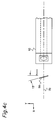
- Fig. 4C illustrates the relative positioning of readout sensor 56 with respective to laser block 10 and lasing plane 70.
- an X and Y axis is shown for reference and the planar surface of optical sensor 56 is held at an angle of 15° with respect to the Y axis.
- readout sensor 56 is held parallel with the Z axis which is defined to go into the plane of the figure. Readout sensor 56 again causes any reflections off initial surface 62 also to be directed out of lasing plane 70.
- corner cube 16 readout sensor 56, and PLC sensor 58 By positioning corner cube 16 readout sensor 56, and PLC sensor 58 to cause any reflection off of their planar surfaces to be directed out of the lasing plane the possibility of undesired scatter coupling back into the laser cavity is reduced. As previously discussed, this scatter coupling into the laser cavity detrimentally effects performance and contributes to the problems of lock-in. By positioning all of these optical elements appropriately low rate performance is improved.
Landscapes
- Physics & Mathematics (AREA)
- Engineering & Computer Science (AREA)
- Electromagnetism (AREA)
- Optics & Photonics (AREA)
- Power Engineering (AREA)
- General Physics & Mathematics (AREA)
- Radar, Positioning & Navigation (AREA)
- Remote Sensing (AREA)
- Plasma & Fusion (AREA)
- Gyroscopes (AREA)
- Lasers (AREA)
Claims (10)
- Ringlaserkreisel (50), aufweisend:einen Kreiselblock (10) enthaltend eine Polygonstrecke in geschlossener Schleife zur Unterstützung eines ersten gegenläufigen optischen Signales (20) und eines zweiten gegenläufigen optischen Signales innerhalb einer einzigen Laserebene, wobei der Block mehrere Ecken aufweist;einen Ausgangsspiegel (14), der mit dem Block (10) an einer Ecke des Blockes befestigt ist, wobei der Ausgangsspiegel so positioniert ist, daß er das erste gegenläufige optische Signal und das zweite gegenläufige optische Signal an einer Oberfläche des Ausgangsspiegels empfängt, einen Teil der optischen Signale reflektiert, während er den verbleibenden Teil der optischen Signale überträgt;eine Eckwürfeleinrichtung (16), die hinter dem Ausgangsspiegel (14) positioniert ist, um ein optisches Signal zu empfangen, das optische Signal umzusetzen und das optische Signal zurück gegen den Ausgangsspiegel zu übertragen, wobei der Eckwürfel eine Empfangs-Oberfläche (62) und mehrere reflektierende Oberflächen (64,66,68) aufweist, undeinen optischen Auslesesensor (56), der hinter dem Ausgangsspiegel (14) positioniert ist, um ein kombiniertes Signal zu empfangen, das eine Kombination des ersten optischen Signales und des zweiten optischen Signales umfaßt und um ein elektrisches Signal zu erzeugen, das das kombinierte Signal anzeigt,dadurch gekennzeichnet, daßdie Empfangs-Oberfläche (62) der Eckwürfeleinrichtung (16) so ausgerichtet ist, daß sie nicht senkrecht zu der Laserebene ist; unddie optische Ausleseeinrichtung (56) eine planare Oberfläche besitzt, die so ausgerichtet ist, daß sie nicht senkrecht zu der Laserebene ist.
- Ringlaserkreisel nach Anspruch 1, gekennzeichnet durch:
eine Optik-Halteeinrichtung (54) zum Positionieren der Auslese-Sensoreinrichtung (56) so, daß das kombinierte optische Signal die Oberfläche der Auslese-Sensoreinrichtung schneidet, während die Oberfläche nicht senkrecht zu der Ebene ist, in der das erste optische Signal und das zweite optische Signal umlaufen, wobei die Optik-Halteeinrichtung (54) ebenfalls die Eckwürfeleinrichtung (16) so positioniert, daß sie das erste optische Signal empfängt, während irgendwelche planare Oberflächen der Eckwürfeneinrichtung nicht senkrecht zu der Ebene sind, in welcher die ersten und zweiten optischen Signale umlaufen. - Ringlaserkreisel nach Anspruch 2, ferner gekennzeichnet durch eine Intensitäts-Sensoreinrichtung (58), die mit der Optik-Halteeinrichtung (54) befestigt ist, um ein optisches Signal aufzunehmen und ein elektrisches Signal auszugeben, das die Intensität des optischen Signales anzeigt, wobei die Intensitäts-Sensoreinrichtung (58) so positioniert ist, daß sie nicht senkrecht zu der Ebene ist, in welcher die ersten und zweiten optischen Signale umlaufen.
- Ringlaserkreisel nach Anspruch 2, dadurch gekennzeichnet, daß die planare Oberfläche des Auslesesensors (56) so ausgerichtet ist, daß eine Linie, die durch den Schnitt zwischen der Laserebene und der planaren Oberfläche des optischen Auslesesensors gebildet wird, senkrecht zu dem kombinierten optischen Signal ist, daß die Empfangs-Oberfläche der Eckwürfeleinrichtung (16) so ausgerichtet ist, daß eine Linie, die durch den Schnitt zwischen der Laserebene und der Empfangs-Oberfläche der Eckwürfeleinrichtung gebildet wird, senkrecht zu dem übertragenen ersten optischen Signal ist, und
daß die planare Oberfläche der Intensitäts-Sensoreinrichtung (58) so ausgerichtet ist, daß eine Linie, die durch den Schnitt zwischen der Laserebene und der planaren Oberfläche der Intensitäts-Sensoreinrichtung gebildet wird, senkrecht zu dem kombinierten optischen Signal ist. - Ringlaserkreisel nach Anspruch 4, dadurch gekennzeichnet, daß die planare Oberfläche des Auslesesensors (56), die Empfangs-Oberfläche (62) des Eckwürfels (16) und die planare Oberfläche der Intensitäts-Sensoreinrichtung (58) unter einem Winkel von 75 Grad in Bezug auf die Laserebene ausgerichtet sind.
- Ringlaserkreisel (50) zur Erfassung der Drehung, aufweisend:ein Kreiselgehäuse (40);eine Dithereinrichtung (38), die mit dem Kreiselgehäuse befestigt ist, um eine Drehschwingung vorzugeben;einen Kreiselblock (10), der mit der Dithereinrichtung (38) befestigt ist, wobei der Kreiselblock eine Polygonstrecke in geschlossener Schleife enthält, zur Unterstützung eines ersten optischen Signales (20) und eines zweiten optischen Signales (22) innerhalb einer einzigen Laserebene, wobei das erste optische Signal und das zweite optische Signal entlang der geschlossenen Wegstrecke in entgegengesetzten Richtungen umlaufen und der Kreiselblock mehrere Ecken aufweist;einen Ausgangsspiegel (14), der mit dem Block an einer Ecke des Blockes befestigt ist, wobei der Ausgangsspiegel so positioniert ist, daß er das erste optische Signal und das zweite optische Signal an einer Oberfläche des Ausgangsspiegels empfängt, einen Teil der optischen Signale reflektiert, während er den verbleibenden Teil der optischen Signale überträgt;eine Eckwürfeleinrichtung (16), die mit dem Kreiselgehäuse (40) befestigt ist und hinter dem Ausgangsspiegel (14) positioniert ist, wobei die Eckwürfeleinrichtung das erste optische Signal empfängt, das erste optische Signal umsetzt und das erste optische Signal zurück zu dem Ausgangsspiegel überträgt, wobei der Eckwürfel eine Empfangs-Oberfläche (62) und mehrere reflektierende Oberflächen (64,66,68) besitzt;einen optischen Auslesesensor (56), der mit dem Kreiselgehäuse (40) befestigt ist und hinter dem Ausgangsspiegel (14) positioniert ist, um ein kombiniertes Signal zu empfangen, das eine Kombination des ersten optischen Signales und des zweiten optischen Signales umfaßt und um ein elektrisches Signal zu erzeugen, das das kombinierte Signal anzeigt, wobei der optische Auslesesensor eine planare Oberfläche besitzt; undeinen PLC-Sensor (58), der mit dem Kreiselgehäuse (40) befestigt ist, um das erste optische Signal aufzunehmen und ein elektrisches Signal zu erzeugen, das das erste optische Signal anzeigt, wobei der PLC-Sensor eine planare Oberfläche für die Aufnahme des ersten optischen Signales besitzt,dadurch gekennzeichnet, daß:
die Empfangs-Oberfläche (62) der Eckwürfeleinrichtung (16) so ausgerichtet ist, daß sie nicht senkrecht zu der Laserebene ist und daß der optische Auslesesensor (56) und der PLC-Sensor (58) mit ihren planaren Oberflächen so ausgerichtet sind, daß sie nicht senkrecht zu der Laserebene sind. - Ringlaserkreisel nach Anspruch 6, dadurch gekennzeichnet, daß die Empfangs-Oberfläche (62) der Eckwürfeleinrichtung (16) so ausgerichtet ist, daß eine Linie, die durch den Schnitt zwischen der Laserebene und der Empfangs-Oberfläche der Eckwürfeleinrichtung gebildet wird, senkrecht zu dem übertragenen ersten optischen Signal steht.
- Ringlaserkreisel nach Anspruch 6, dadurch gekennzeichnet, daß die planare Oberfläche des optischen Auslesesensors (56) so ausgerichtet ist, daß eine Linie, die durch den Schnitt zwischen der Laserebene und der planaren Oberfläche des optischen Auslesesensors gebildet wird, senkrecht zu dem kombinierten optischen Signal steht.
- Ringlaserkreisel nach Anspruch 6, dadurch gekennzeichnet, daß die planare Oberfläche des PLC-Sensor (58) so ausgerichtet ist, daß eine Linie, die durch den Schnitt zwischen der Laserebene und der planaren Oberfläche des PLC-Sensors gebildet wird, senkrecht zu dem kombinierten optischen Signal steht.
- Ringlaserkreisel nach den Ansprüchen 7 bis 9, dadurch gekennzeichnet, daß die planare Oberfläche des optischen Auslesesensors (56), die Empfangs-Oberfläche (62) des Eckwürfels (16) und die planare Oberfläche des optischen PLC-Sensors (58) unter einem Winkel von 75 Grad in Bezug auf die Laserebene ausgerichtet sind.
Applications Claiming Priority (3)
| Application Number | Priority Date | Filing Date | Title |
|---|---|---|---|
| US08/000,775 US5386289A (en) | 1993-01-05 | 1993-01-05 | Case mounted readout for providing a ring laser gyro with low backscatter |
| PCT/US1994/000117 WO1994016291A1 (en) | 1993-01-05 | 1994-01-04 | Case mounted readout modification for improved low rate performance |
| US775 | 1995-06-30 |
Publications (2)
| Publication Number | Publication Date |
|---|---|
| EP0678190A1 EP0678190A1 (de) | 1995-10-25 |
| EP0678190B1 true EP0678190B1 (de) | 1997-10-01 |
Family
ID=21692980
Family Applications (1)
| Application Number | Title | Priority Date | Filing Date |
|---|---|---|---|
| EP94907144A Expired - Lifetime EP0678190B1 (de) | 1993-01-05 | 1994-01-04 | Gehäusemontierte Auslesesignalverarbeitungsanlage für verbesserte Leistung bei niedriger Drehrate |
Country Status (6)
| Country | Link |
|---|---|
| US (1) | US5386289A (de) |
| EP (1) | EP0678190B1 (de) |
| JP (1) | JPH08505474A (de) |
| CA (1) | CA2134969A1 (de) |
| DE (1) | DE69405974T2 (de) |
| WO (1) | WO1994016291A1 (de) |
Families Citing this family (2)
| Publication number | Priority date | Publication date | Assignee | Title |
|---|---|---|---|---|
| US9759565B2 (en) | 2015-01-15 | 2017-09-12 | Honeywell International Inc. | Radio frequency ring laser gyroscope including a multiple electrode system and an impedance matching circuit |
| US12584743B2 (en) | 2023-09-19 | 2026-03-24 | Honeywell International Inc. | Method and assembly to reduce external laser light scattering source in ring laser gyroscope |
Family Cites Families (6)
| Publication number | Priority date | Publication date | Assignee | Title |
|---|---|---|---|---|
| US3373650A (en) * | 1965-04-02 | 1968-03-19 | Honeywell Inc | Laser angular rate sensor |
| CA948435A (en) * | 1971-01-21 | 1974-06-04 | Joseph E. Killpatrick | Laser angular rate sensor read-out apparatus |
| US4167336A (en) * | 1977-03-29 | 1979-09-11 | The Singer Company | Ring laser gyroscope having wedge desensitizing optical means |
| US4190364A (en) * | 1977-09-07 | 1980-02-26 | The Singer Company | Ring laser gyroscope |
| US4582429A (en) * | 1983-04-06 | 1986-04-15 | Honeywell | Readout for a ring laser |
| US4712917A (en) * | 1984-10-26 | 1987-12-15 | Honeywell Inc. | Readout for a ring laser gyro |
-
1993
- 1993-01-05 US US08/000,775 patent/US5386289A/en not_active Expired - Fee Related
-
1994
- 1994-01-04 DE DE69405974T patent/DE69405974T2/de not_active Expired - Fee Related
- 1994-01-04 EP EP94907144A patent/EP0678190B1/de not_active Expired - Lifetime
- 1994-01-04 CA CA002134969A patent/CA2134969A1/en not_active Abandoned
- 1994-01-04 JP JP6516171A patent/JPH08505474A/ja active Pending
- 1994-01-04 WO PCT/US1994/000117 patent/WO1994016291A1/en not_active Ceased
Also Published As
| Publication number | Publication date |
|---|---|
| DE69405974D1 (de) | 1997-11-06 |
| US5386289A (en) | 1995-01-31 |
| DE69405974T2 (de) | 1998-03-12 |
| CA2134969A1 (en) | 1994-07-21 |
| JPH08505474A (ja) | 1996-06-11 |
| EP0678190A1 (de) | 1995-10-25 |
| WO1994016291A1 (en) | 1994-07-21 |
Similar Documents
| Publication | Publication Date | Title |
|---|---|---|
| US4477188A (en) | Monolithic three axis ring laser gyroscope | |
| US4708480A (en) | Solid-state optical interferometer | |
| EP2128566B1 (de) | Verlässlicher Hohlkern-Faserresonator mit geringem Verlust | |
| JP2008089594A (ja) | 光学式共振器ジャイロスコープ、および共振非対称誤差を低減するための方法 | |
| US4410274A (en) | Ring laser gyroscope with doppler mirrors and offset actuators | |
| EP3771888B1 (de) | Umschalten eines sbs-kreisels mit fester pumpentrennung | |
| US5408317A (en) | Scattered light moire-brillouin gyroscope | |
| US4884283A (en) | Ring laser gyroscope mirror orientation system and method | |
| US5386289A (en) | Case mounted readout for providing a ring laser gyro with low backscatter | |
| JP2001066142A (ja) | 共振型光ジャイロ | |
| US5311538A (en) | Case-mounted RLG readout having block mounted optical sensor | |
| US4536087A (en) | Dither compensator for ring laser gyroscope | |
| US4582429A (en) | Readout for a ring laser | |
| US4986661A (en) | Solid state fiber optic semiconductor ring laser apparatus | |
| JP2835874B2 (ja) | リングレーザジャイロ装置 | |
| CA2122027C (en) | Laser intensity monitoring apparatus with metallic thin film mask | |
| EP0129838A2 (de) | Ringlaser für einen Winkelgeschwindigkeitsmesser | |
| US5737080A (en) | Solid state nonplanar laser gyroscope | |
| JP2835468B2 (ja) | リングレーザジャイロ装置 | |
| CA1275722C (en) | Simplified readout optics for a ring laser apparatus | |
| EP0246352B1 (de) | Auslesevorrichtung für einen Ringlaserkreisel | |
| US5926274A (en) | Very low expansion radiation hardened transmission medium | |
| KR100186906B1 (ko) | 고체 비평면 레이저 자이로스코프 | |
| JP2517696Y2 (ja) | リングレ−ザジヤイロ | |
| JPH11344645A (ja) | 光モジュール及びそれを使用する光学機器 |
Legal Events
| Date | Code | Title | Description |
|---|---|---|---|
| PUAI | Public reference made under article 153(3) epc to a published international application that has entered the european phase |
Free format text: ORIGINAL CODE: 0009012 |
|
| 17P | Request for examination filed |
Effective date: 19950616 |
|
| AK | Designated contracting states |
Kind code of ref document: A1 Designated state(s): DE FR GB IT SE |
|
| GRAG | Despatch of communication of intention to grant |
Free format text: ORIGINAL CODE: EPIDOS AGRA |
|
| GRAH | Despatch of communication of intention to grant a patent |
Free format text: ORIGINAL CODE: EPIDOS IGRA |
|
| GRAH | Despatch of communication of intention to grant a patent |
Free format text: ORIGINAL CODE: EPIDOS IGRA |
|
| 17Q | First examination report despatched |
Effective date: 19970319 |
|
| GRAA | (expected) grant |
Free format text: ORIGINAL CODE: 0009210 |
|
| AK | Designated contracting states |
Kind code of ref document: B1 Designated state(s): DE FR GB IT SE |
|
| PG25 | Lapsed in a contracting state [announced via postgrant information from national office to epo] |
Ref country code: IT Free format text: LAPSE BECAUSE OF FAILURE TO SUBMIT A TRANSLATION OF THE DESCRIPTION OR TO PAY THE FEE WITHIN THE PRE;WARNING: LAPSES OF ITALIAN PATENTS WITH EFFECTIVE DATE BEFORE 2007 MAY HAVE OCCURRED AT ANY TIME BEFORE 2007. THE CORRECT EFFECTIVE DATE MAY BE DIFFERENT FROM THE ONE RECORDED.SCRIBED TIME-LIMIT Effective date: 19971001 Ref country code: FR Free format text: THE PATENT HAS BEEN ANNULLED BY A DECISION OF A NATIONAL AUTHORITY Effective date: 19971001 |
|
| REF | Corresponds to: |
Ref document number: 69405974 Country of ref document: DE Date of ref document: 19971106 |
|
| ET | Fr: translation filed | ||
| PG25 | Lapsed in a contracting state [announced via postgrant information from national office to epo] |
Ref country code: GB Free format text: LAPSE BECAUSE OF NON-PAYMENT OF DUE FEES Effective date: 19980104 |
|
| PG25 | Lapsed in a contracting state [announced via postgrant information from national office to epo] |
Ref country code: SE Free format text: LAPSE BECAUSE OF NON-PAYMENT OF DUE FEES Effective date: 19980105 |
|
| PLBE | No opposition filed within time limit |
Free format text: ORIGINAL CODE: 0009261 |
|
| STAA | Information on the status of an ep patent application or granted ep patent |
Free format text: STATUS: NO OPPOSITION FILED WITHIN TIME LIMIT |
|
| GBPC | Gb: european patent ceased through non-payment of renewal fee |
Effective date: 19980104 |
|
| 26N | No opposition filed | ||
| PG25 | Lapsed in a contracting state [announced via postgrant information from national office to epo] |
Ref country code: DE Free format text: LAPSE BECAUSE OF NON-PAYMENT OF DUE FEES Effective date: 19981001 |
|
| EUG | Se: european patent has lapsed |
Ref document number: 94907144.3 |
|
| REG | Reference to a national code |
Ref country code: FR Ref legal event code: ST |