EP0678202B1 - Appareil de revelation d'images latentes - Google Patents
Appareil de revelation d'images latentes Download PDFInfo
- Publication number
- EP0678202B1 EP0678202B1 EP93902581A EP93902581A EP0678202B1 EP 0678202 B1 EP0678202 B1 EP 0678202B1 EP 93902581 A EP93902581 A EP 93902581A EP 93902581 A EP93902581 A EP 93902581A EP 0678202 B1 EP0678202 B1 EP 0678202B1
- Authority
- EP
- European Patent Office
- Prior art keywords
- image
- developer
- toner
- roller
- applicator
- Prior art date
- Legal status (The legal status is an assumption and is not a legal conclusion. Google has not performed a legal analysis and makes no representation as to the accuracy of the status listed.)
- Expired - Lifetime
Links
- 239000007788 liquid Substances 0.000 claims abstract description 53
- 239000002245 particle Substances 0.000 claims abstract description 34
- 238000003384 imaging method Methods 0.000 claims abstract description 14
- 239000000758 substrate Substances 0.000 claims abstract description 11
- 238000004140 cleaning Methods 0.000 claims description 24
- 239000007787 solid Substances 0.000 claims description 17
- 239000012141 concentrate Substances 0.000 claims description 16
- 230000005684 electric field Effects 0.000 claims description 10
- 239000011148 porous material Substances 0.000 claims 1
- 239000010410 layer Substances 0.000 description 94
- 108091008695 photoreceptors Proteins 0.000 description 21
- 239000000463 material Substances 0.000 description 20
- 238000000034 method Methods 0.000 description 11
- 230000000694 effects Effects 0.000 description 4
- 229920001971 elastomer Polymers 0.000 description 4
- 239000000806 elastomer Substances 0.000 description 4
- 238000001962 electrophoresis Methods 0.000 description 4
- 229910052751 metal Inorganic materials 0.000 description 4
- 239000002184 metal Substances 0.000 description 4
- 230000003287 optical effect Effects 0.000 description 4
- 239000011248 coating agent Substances 0.000 description 3
- 238000000576 coating method Methods 0.000 description 3
- 238000010586 diagram Methods 0.000 description 3
- 230000005686 electrostatic field Effects 0.000 description 3
- 230000006870 function Effects 0.000 description 3
- 229920002635 polyurethane Polymers 0.000 description 3
- 239000004814 polyurethane Substances 0.000 description 3
- 238000005299 abrasion Methods 0.000 description 2
- 230000001419 dependent effect Effects 0.000 description 2
- 239000010408 film Substances 0.000 description 2
- 239000012530 fluid Substances 0.000 description 2
- 239000000203 mixture Substances 0.000 description 2
- 238000002360 preparation method Methods 0.000 description 2
- 239000012858 resilient material Substances 0.000 description 2
- 238000005201 scrubbing Methods 0.000 description 2
- OKTJSMMVPCPJKN-UHFFFAOYSA-N Carbon Chemical compound [C] OKTJSMMVPCPJKN-UHFFFAOYSA-N 0.000 description 1
- 229910000975 Carbon steel Inorganic materials 0.000 description 1
- 229920003308 DuPont™ Surlyn® 1605 Polymers 0.000 description 1
- BUGBHKTXTAQXES-UHFFFAOYSA-N Selenium Chemical compound [Se] BUGBHKTXTAQXES-UHFFFAOYSA-N 0.000 description 1
- AZDRQVAHHNSJOQ-UHFFFAOYSA-N alumane Chemical group [AlH3] AZDRQVAHHNSJOQ-UHFFFAOYSA-N 0.000 description 1
- CEGOLXSVJUTHNZ-UHFFFAOYSA-K aluminium tristearate Chemical compound [Al+3].CCCCCCCCCCCCCCCCCC([O-])=O.CCCCCCCCCCCCCCCCCC([O-])=O.CCCCCCCCCCCCCCCCCC([O-])=O CEGOLXSVJUTHNZ-UHFFFAOYSA-K 0.000 description 1
- 229940063655 aluminum stearate Drugs 0.000 description 1
- 239000006229 carbon black Substances 0.000 description 1
- 239000010962 carbon steel Substances 0.000 description 1
- 238000005266 casting Methods 0.000 description 1
- 238000013329 compounding Methods 0.000 description 1
- 230000006835 compression Effects 0.000 description 1
- 238000007906 compression Methods 0.000 description 1
- 239000002322 conducting polymer Substances 0.000 description 1
- 239000002482 conductive additive Substances 0.000 description 1
- 229920001940 conductive polymer Polymers 0.000 description 1
- 238000010276 construction Methods 0.000 description 1
- 230000008021 deposition Effects 0.000 description 1
- 238000007599 discharging Methods 0.000 description 1
- 239000006260 foam Substances 0.000 description 1
- 238000000227 grinding Methods 0.000 description 1
- 229920000554 ionomer Polymers 0.000 description 1
- 239000004922 lacquer Substances 0.000 description 1
- 235000013372 meat Nutrition 0.000 description 1
- 238000002156 mixing Methods 0.000 description 1
- 239000013047 polymeric layer Substances 0.000 description 1
- 229910052711 selenium Inorganic materials 0.000 description 1
- 239000011669 selenium Substances 0.000 description 1
- 229940065287 selenium compound Drugs 0.000 description 1
- 150000003343 selenium compounds Chemical class 0.000 description 1
- 238000005549 size reduction Methods 0.000 description 1
- 239000010409 thin film Substances 0.000 description 1
Images


Classifications
-
- G—PHYSICS
- G03—PHOTOGRAPHY; CINEMATOGRAPHY; ANALOGOUS TECHNIQUES USING WAVES OTHER THAN OPTICAL WAVES; ELECTROGRAPHY; HOLOGRAPHY
- G03G—ELECTROGRAPHY; ELECTROPHOTOGRAPHY; MAGNETOGRAPHY
- G03G15/00—Apparatus for electrographic processes using a charge pattern
- G03G15/06—Apparatus for electrographic processes using a charge pattern for developing
- G03G15/10—Apparatus for electrographic processes using a charge pattern for developing using a liquid developer
-
- G—PHYSICS
- G03—PHOTOGRAPHY; CINEMATOGRAPHY; ANALOGOUS TECHNIQUES USING WAVES OTHER THAN OPTICAL WAVES; ELECTROGRAPHY; HOLOGRAPHY
- G03G—ELECTROGRAPHY; ELECTROPHOTOGRAPHY; MAGNETOGRAPHY
- G03G15/00—Apparatus for electrographic processes using a charge pattern
- G03G15/06—Apparatus for electrographic processes using a charge pattern for developing
- G03G15/10—Apparatus for electrographic processes using a charge pattern for developing using a liquid developer
- G03G15/101—Apparatus for electrographic processes using a charge pattern for developing using a liquid developer for wetting the recording material
Definitions
- the present invention relates to development apparatus in general and, more particularly, to latent image development apparatus in electrophotographic imaging systems.
- the method of developing a latent image formed on a photoconductive surface by means of electrophoretic transfer of liquid toner is well known in the art.
- charged particles suspended in a non-polar insulating carrier liquid migrate under the influence of an electrostatic field and concentrate in an image forming configuration upon relatively charged or discharged areas of a photoconductive surface.
- the developed image is then transferred to a substrate, such as paper, either directly or by means of one or more intermediate transfer members.
- Canadian Patent 990589 a method of developing electrostatic images is described which involves producing a film of liquid toner on a first applicator and bringing the applicator in contact with the final substrate which carries a latent image, thereby to develop the image. A second applicator bearing a layer of carrier liquid is then brought into contact with the substrate to remove background deposits and to squeegee out excess liquid.
- the film of liquid toner described in Canadian Patent 990589 has between 2 - 4 per cent of toner concentrate dispersed within the carrier liquid.
- a latent image development apparatus described in U.S. Patent No. 4,327,664 includes a porous, resilient sponge, development roller which is circumferentially surrounded by a net of fine mesh size.
- the developer roller is urged against the latent image carrying surface of a drum and liquid toner, which is carried in the roller is squeezed out of the compressed sponge through the fine net.
- Toner particles which are contained in the liquid toner are selectively deposited, by electrophoresis, onto the surface of the drum to form an image.
- U.S. Patent 4,400,079 describes a liquid toner development system for developing a latent image on a photoreceptor that uses a non-contacting developer roller.
- the development roller surface may move in the same direction as the photoreceptor surface or in the opposite direction.
- a developer roller preferably made of resilient material, is urged against an image forming surface, such as a photoreceptor, that has an electrostatic latent image comprising image areas at a first voltage and background areas at a second voltage formed thereon.
- the developer roller is coated with a relatively thin film of concentrated liquid toner material having a given layer thickness. At least a portion of this layer thickness is selectively transferred to the image-forming surface in accordance with the latent image formed thereon.
- the developer is electrified to a voltage which is intermediate the first and second voltages.
- the developer voltage is selected to cause only a portion of the layer thickness to transfer to the image areas of the latent image.
- DMA density of toner particles per unit area
- the thickness uniformity of the toner concentrate layer on the developer is improved by supplying the toner concentrate preferably from a sponge roller which is urged against the developer roller and which travels at a different speed from that of the developer roller at the point of contact between the two rollers. Increased uniformity results even if the toner concentrate remaining on the developer roller is not removed from the roller before application of a new layer of toner concentrate.
- the applicator roller and developer rollers move at the same speed at the point of contact, there is a substantial "memory" of the prior image which non-uniformly effects the developed toner particle mass per unit area (DMA) in the layer on the developer roller.
- DMA developed toner particle mass per unit area
- the concentration of toner particles on the layer is increased by application of an electrified squeegee roller to the layer before the transfer to the imaging surface.
- the applicator roller moves in a direction opposite to that of the developer roller at the point of contact between them.
- the developer roller is coated by developing thereon a layer of toner particles by electrophoresis from liquid toner using a stationary plate type developer.
- the coating step is followed by squeegeeing the layer on the developer roller with a squeegee roller at a high voltage and with high pressure in order to remove a large portion of the liquid therein, before transfer of all or a portion of the resultant thickness of the layer to the image forming surface.
- material remaining on the developer roller after development of the latent image is preferably removed in a cleaning step before the recoating of the developer roller.
- the developer roller may be cleaned by a tandem roller system in which a first, biased squeegee, roller removes the toner particles from the developer roller by electrostatic transfer.
- a second, sponge cleaning, roller removes the toner particles from the biased squeegee roller by abrasion, preferably aided by an electrostatic field.
- the toner is removed from the sponge roller by a blade which indents the surface of the sponge and scrapes the material which is extruded away.
- one or both of the squeegee-developer or squeegee-sponge surfaces is wetted by a cleaning liquid or dilute toner to aid in transfer and removal of the toner particles.
- the toner so removed is preferably recycled and used for recoating the developer roller.
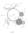
- FIG. 1 and 2 illustrate imaging apparatus constructed and operative in accordance with a preferred embodiment of the present invention.
- the apparatus includes a drum 10 preferably having a cylindrical photoreceptor surface 16 made of selenium, a selenium compound, an organic photoconductor or any other suitable photoconductor known in the art.
- drum 10 rotates in the direction indicated by arrow 13 and photoreceptor surface 16 is charged by a charger 18 to a generally uniformly predetermined voltage, typically on the order of 1000 volts.
- Charger 18 may be any type of charger known in the art, such as a corotron, a scorotron or a roller.
- a light source 19 which may be a laser scanner (in the case of a printer) or the projection of an original (in the case of a photocopier).
- Light source 19 forms a desired latent image on charged photoreceptor surface 16 by selectively discharging a portion of the photoreceptor surface, the image portions being at a first voltage and the background portions at a second voltage.
- the discharged portions preferably have a voltage of less than about 100 volts.
- drum 10 brings the selectively charged photoreceptor surface 16 into operative contact engagement with a surface 21 of a developer roller 22.
- Developer roller 22 preferably rotates in a sense opposite that of drum 10, as shown by arrow 13, such that there is substantially zero relative motion between their respective surfaces at the point of contact. Developer roller 22 is most preferably urged against drum 10.
- developer roller 22 is formed with a metal core coated with, preferably, 1-2 mm of a soft elastomer material having a Shore A hardness of preferably 20-40. In one embodiment of the invention, this coating is made conductive, preferably, to a resistivity between 10 5 and 10 7 ohm-cm. In this embodiment, the conductive layer is either covered with a smooth elastomer layer or is formed by casting or other process to have a smooth surface, preferably better than N3.
- the soft elastomer material which may be non-conductive, is coated with a very thin electroconductive layer, such as for example a metal or conducting lacquer layer, which is electrically attached to the metal core.
- a very thin electroconductive layer such as for example a metal or conducting lacquer layer, which is electrically attached to the metal core.
- This conductive layer is preferably covered by a thin (preferably 15 to 60 micrometer) layer of conducting polymer having a resistivity, preferably, between 10 7 to 10 9 ohm-cm.
- drum 10 may be formed of a relatively resilient material, and surface 21 may be composed of either a rigid or compliant material.
- surface 21 is coated with a thin layer of liquid toner, which is preferably very highly concentrated liquid toner.
- Developer roller 22 itself is charged to a voltage which is intermediate the voltage of the charged and discharged areas on photoreceptor surface 16.
- liquid toner having a very high concentration of solids at development is used, as in the preferred embodiments of the present invention, there is little if any electrophoresis and the entire thickness of the layer or a controllable portion of the thickness is transferred to the image areas of the latent image at substantially the same toner concentration as the layer on the developer surface.
- the voltage difference between the image portions of the latent image and the developer roller is reduced to a value at which only part of the thickness of the toner concentrate layer is transferred from the developer roller to the image portions of the latent image.
- the thickness of the layer that is transferred depends mainly on the charge per unit volume in the layer and depends only slightly on the local thickness or solids concentration of the layer. Thus, even if the layer on the developer roller is not uniform, the layer transferred to the image areas has a uniform DMA and thus a uniform optical density.
- This phenomenon is probably due to the following effect:
- a voltage is applied across the toner concentrate layer between the development roller and the image areas on the image forming surface, an electric field between the two surfaces is generated. This field is strongest at the image-forming surface and is reduced by the charge in the layer, at points within the layer itself.
- the electric field within the layer is unidirectional, and acts to urge the entire toner layer toward the imaging surface at image regions.
- the impressed voltage is low, the electric field may reverse at some point in the layer. For those portions of the layer between this point and the developer roller the electric field actually acts to force the toner particles toward the developer roller.
- the layer will split at or near this point, with part of the toner layer being transferred to the image-forming surface and part remaining on the developer roller.
- the amount of solids which is transferred is dependent only on the charge per unit mass in the layer and is not a strong function of the layer thickness or the exact concentration of toner particles in the layer.
- the DMA is basically directly proportional to the voltage difference applied, the DMA can be easily controlled by changing this voltage.
- a sensor 100 is placed on the image forming surface downstream of the development region to measure the optical density of the image (and hence the DMA).
- control electronics 102 which is operative to control a power supply 104 which supplies voltage to developer roller 22.
- the preferred liquid toner of the invention is utilized at a concentration of 25-30% toner particles on the developer layer at a DMA of 0.2 mgm/cm 2 (with variations of between about 0.17 and 0.25 mgm/cm 2 ), the transferred layer will preferably be about 0.15 mgm/cm 2 with worst case variations of less than ⁇ 10%.
- a plurality of developer rollers may be provided, one for each color, spaced circumferentially around the photoreceptor which are sequentially engaged with photoreceptor surface 16 to develop sequentially-produced latent images.
- roller 22 is coated by an applicator assembly generally indicated by reference numeral 23.
- the necessary pressure for dispensing the toner is preferably supplied by a small pump (not shown) which pumps the toner from a toner container (not shown) at a preset pressure.
- a small pump (not shown) which pumps the toner from a toner container (not shown) at a preset pressure.
- Any suitable pump and any suitable container known in the art may be used for this purpose, as well as any other suitable means for providing the desired toner pressure (such as a pressured tank containing the desired liquid toner).
- surplus toner unabsorbed by layer 68 returns to the container for reuse.
- developer roller 22 and applicator roller 65 rotate in the same rotational direction (indicated by arrows 13 and 70 in Fig. 2, respectively), such that their surfaces move in opposite directions.
- applicator roller 65 is operative to scrub surface 21 and to remove the residual toner (which normally remains after the selective transfer of toner to surface 16) on surface 21 while applying a new, homogeneous, toner layer to the surface electrophoretically.
- the absolute velocity of surface 64 is preferably approximately 2 - 3 times greater than that of surface 21.
- the DMA on the development roller will be uneven, with up to 30% variations. Furthermore, the toner which remains on the developer roller after development of the image is highly concentrated, and not easily removed, especially if a sponge roller is used for cleaning, so as not to damage surface 21.
- the residual toner is scraped off surface 21 by the open cells of surface 64, due to the substantial relative motion between the surfaces and the pressure applied by spring 72.
- the scraped toner is indistinguishably mixed with the new toner carried by surface 64, and a homogeneous layer of toner remains on surface 21 as the surfaces disengage at divergence line 76.
- a liquid toner of 5% - 10% solids concentration is supplied by dispenser 62 to roller 65. After application onto the developer roller, the layer has a solids concentration of between 15 and 20 percent.
- applicator 65 may further or alternatively be connected to an a.c voltage source, which is operative to somewhat reduce the viscosity of the toner and generally to cause the deposition of a smoother layer on surface 21 of developer roller 22.
- liquid toner layer which develops the latent image have as high a solids concentration as possible, preferably 30-50%.
- applicator assembly 23 further includes a squeegee roller 78 in operative contact with roller 22 downstream of dispenser roller 65 and before roller 22 contacts drum 10.
- squeegee roller 78 is electrified with a voltage comparable with that of applicator 65, such that the outer surface of the squeegee repels the charged particles of the toner layer on surface 21.
- Squeegee roller 78 is also preferably resiliently urged against roller 22 such that liquid carrier is removed from the layer as it passes the squeegee roller.
- the mechanical pressure and the electric repulsion of roller 78 are operative to squeegee the layer of toner, so that the layer is more condensed and uniform as the layer reaches image carrying surface 16.
- the liquid toner is supplied to roller 78 at a concentration less than that required for optimal development of the latent image.
- roller 78 When roller 78 is urged against surface 21 of developer roller 22, it mechanically removes excess toner fluid from the layer impressed on surface 21, and when charged with a suitable electric potential, it repels the charged toner particles and causes them to more closely adhere to surface 21. The excess fluid which has been removed is recovered for reuse.
- the solids content of the layer is mainly a function of the mechanical properties of the rollers and of the applied voltages and pressures and is only slightly influenced by the initial concentration for a considerable range of initial toner concentrations.
- squeegee roller 78 comprises an aluminum core which is anodized and coated with a thin layer (approximately 50 micrometers) of polyurethane.
- a cleaning station 82 may be provided, which may comprise a sponge or a brush or similar apparatus, to remove the excess toner concentrate from surface 21 of developer roller 22. The toner so removed may then be pumped back for reuse, after mixture with fresh toner, through dispenser 62 into the sponge of applicator 65.
- Cleaning station 82 preferably comprises a sponge roller 84, which is preferably formed of a resilient open cell material similar to that of layer 68 of roller 65.
- Roller 84 is situated such that it resiliently engages a portion of surface 21 between the transfer area (i.e. the area of surface 21 engaged by surface 16) and the application area (i.e. the area of surface 21 engaged by surface 64), thereby removing residual toner from surface 21 before the application of new toner.
- sponge 84 may be supplied with toner carrier liquid which may assist in cleaning surface 21 by loosening and carrying away the residual toner particles scraped off the surface.
- Cleaning 110 comprises a tandem roller arrangement in which a first, biased squeegee, roller 112 removes residual toner particles from developer roller 22 by electrostatic transfer. To this end roller 112 is biased to a voltage that, in conjunction with the developer roller voltage, causes the charged toner particles to be attracted to roller 112.
- the general construction of roller 112 is preferably, similar to that described above for roller 78.
- a second, sponge cleaning, roller 114 removes the toner particles from the biased squeegee roller 112 by abrasion, preferably aided by an electrostatic field.
- the toner is removed from the sponge roller by a blade 116 which indents the surface of the sponge and scrapes the material which is extruded away.
- one or both of the squeegee-developer or squeegee-sponge surfaces is wetted by a cleaning liquid or dilute toner to aid in transfer and removal of the toner particles.
- the toner removed by any of the methods is preferably recycled and used for recoating the developer roller.
- Intermediate transfer member 40 is operative for receiving the toner image from photoreceptor surface 16 and for transferring the toner image to a final substrate 42, such as paper. Disposed internally of intermediate transfer member 40 there may be provided a heater 45, to heat intermediate transfer member 40 as is known in the art. Transfer of the image to intermediate transfer member 40 is preferably aided by providing electrification of intermediate transfer member 40 to provide an electric field between intermediate transfer member 40 and the image areas of photoreceptor surface 16.
- Intermediate transfer member 40 preferably has a conducting layer 44 underlying an elastomer layer 46, which is preferably a slightly conductive resilient polymeric layer.
- photoreceptor surface 16 engages a cleaning station 49, which may be any conventional cleaning station.
- a scraper 56 completes the removal of any residual toner which may not have been removed by cleaning station 49.
- a lamp 58 then completes the cycle by removing any residual charge, characteristic of the previous image, from photoreceptor surface 16.
- liquid toner material for use in the present invention is prepared in the following manner:
- plasticized material 690 g is ground together with 1610 g of Marcol 82 in an attritor charged with 3/16" carbon steel balls.
- the material is ground at 250 RPM for 30 hours at 55°C ⁇ 3°C.
- the resulting material is diluted to 10% non-volatile solids (NVS) content and screened through a 300 micrometer screen to remove unground particles. Any metalic contaminating material in the toner is removed by magnetic treatment and the resulting material is charged with charge director to form a 10% NVS liquid developer, suitable for the present invention.
- NVS non-volatile solids
Landscapes
- Physics & Mathematics (AREA)
- General Physics & Mathematics (AREA)
- Wet Developing In Electrophotography (AREA)
Claims (22)
- Appareil de formation d'image, qui comprend :une surface de formation d'image sur laquelle est formée une image électrostatique latente, l'image électrostatique latente comprenant des zones d'image se trouvant à une première tension et des zones d'arrière-plan se trouvant à une deuxième tension,une surface de révélation, chargée à une troisième tension, intermédiaire entre les première et deuxième tensions, et ayant une deuxième surface poussée contre la surface de formation d'image, en étant adaptée à un contact actif avec elle, au niveau d'une première région, de révélation,un ensemble applicateur, servant à appliquer sur la surface de révélation une couche de toner liquide concentré, qui contient des particules de toner chargées et un liquide porteur,un dispositif révélateur qui révèle l'image latente, la troisième tension étant telle que toute l'épaisseur de la couche de toner liquide concentré n'est pas transférée de la surface de révélation aux zones d'image de la surface de formation d'image, afin de former ainsi une image révélée sur la surface de formation d'image, etun moyen servant à transférer l'image révélée de la surface de formation d'image à un substrat final.
- Appareil selon la revendication 1, dans lequel le dispositif révélateur comprend un rouleau de révélation, porté à un potentiel donné tel que le champ électrique produit par la tension du rouleau de révélation, la tension des zones d'image et la charge existant dans la couche de toner, change de direction à l'intérieur de la couche.
- Appareil selon la revendication 1 ou la revendication 2, dans lequel la différence de potentiel entre le rouleau de révélation et la zone d'image est inférieure à 500 Volts.
- Appareil selon l'une quelconque des précédentes revendications, dans lequel la différence de potentiel entre le rouleau de révélation et la zone d'image est supérieure à 300 Volts.
- Appareil selon l'une quelconque des précédentes revendications, dans lequel l'ensemble applicateur comprend :dans lequel l'applicateur et la surface de révélation présentent un mouvement relatif important au niveau de la région d'application.un applicateur ayant une surface adaptée à un contact élastique avec le rouleau de révélation au niveau d'une deuxième région, d'application,un moyen servant à pousser élastiquement l'applicateur en contact avec le rouleau de révélation, au niveau d'une région d'application,un distributeur de toner, servant à fournir à l'applicateur du toner liquide qui contient des particules de toner chargées et un liquide porteur,une source d'énergie, servant à porter l'applicateur à une tension telle que le champ électrique produit par la différence de potentiel entre la surface de révélation et l'applicateur au niveau de la région d'application pousse les particules de toner chargées vers la surface de révélation, formant ainsi une couche de concentré de toner liquide chargé sur la surface de révélation,
- Appareil de formation d'image, qui comprend :l'ensemble applicateur comprenant :une surface de formation d'image sur laquelle est formée une image électrostatique latente, l'image électrostatique latente comprenant des zones d'image se trouvant à une première tension et des zones d'arrière-plan se trouvant à une deuxième tension,une surface de révélation, chargée à une troisième tension, intermédiaire entre les première et deuxième tensions, et ayant une deuxième surface poussée contre la surface de formation d'image, en étant adaptée à un contact actif avec elle, au niveau d'une région de révélation,un ensemble applicateur, servant à appliquer sur la surface de révélation une couche de toner liquide concentré, qui contient des particules de toner chargées et un liquide porteur,dans lequel l'applicateur et la surface de révélation présentent un mouvement relatif important au niveau de la région d'application, dans lequel la surface de révélation sert à révéler l'image latente en transférant une partie au moins de l'épaisseur totale de la couche de toner liquide concentré de la surface de révélation aux zones d'image de la surface de formation d'image, pour former ainsi une image révélée sur la surface de formation d'image, etun applicateur ayant une surface adaptée à un contact élastique avec le rouleau de révélation au niveau d'une région d'application.un moyen servant à pousser élastiquement l'applicateur en contact avec la surface de révélation,un distributeur de toner, servant à envoyer à la région d'application du toner liquide qui contient des particules de toner chargées et un liquide porteur,une source d'énergie, servant à porter l'applicateur à une tension telle que le champ électrique produit par la différence de potentiel entre la surface de révélation et l'applicateur au niveau de la région d'application pousse les particules de toner chargées vers le rouleau de révélation, formant ainsi une couche de concentré de toner liquide chargé sur la surface de révélation,un moyen servant à transférer l'image révélée de la surface de formation d'image à un substrat final.
- Appareil selon la revendication 5 ou la revendication 6, dans lequel l'applicateur est un rouleau éponge composé de pores à cellules ouvertes.
- Appareil selon l'une quelconque des revendications 5 à 7, dans lequel l'applicateur et la surface de révélation se déplacent en sens opposés au niveau de la région de révélation.
- Appareil selon la revendication 8, dans lequel le déplacement relatif de l'applicateur et de la surface de révélation vaut entre trois et quatre fois la vitesse absolue de la surface de révélation.
- Appareil selon l'une quelconque des revendications 5 à 9, dans lequel la vitesse relative entre la surface de révélation et l'applicateur est supérieure à 150 mm/s.
- Appareil selon l'une quelconque des revendications 6 à 10, dans lequel le distributeur de toner comprend un tube distributeur perforé, poussé contre l'applicateur en une région éloignée de la région d'application.
- Appareil selon l'une quelconque des revendications 1 à 4, dans lequel l'ensemble applicateur comprend un dispositif de révélation, de type plaque immobile, disposé adjacent à la surface de révélation, et contient un moyen pour envoyer du toner liquide à une région d'application formée entre la plaque et la surface de révélation.
- Appareil selon l'une ou l'autre des revendications 11 ou 12, dans lequel la concentration de solides dans le toner liquide envoyé à l'ensemble applicateur est inférieure à 10%, et la concentration de solides dans les parties avec toner de l'image révélée est d'au moins 25%.
- Appareil selon l'une quelconque des revendications 5 à 13, comprenant en outre un rouleau racleur électrisé, adapté à un contact actif avec la surface de révélation au niveau d'une région de raclage située en aval de la région d'application mais en amont de la région de révélation, servant à racler la couche de toner liquide concentré et à y augmenter la concentration de toner liquide.
- Appareil selon l'une quelconque des revendications 5 à 14, comprenant en outre un poste de nettoyage servant à éliminer le toner résiduel de la surface de révélation, après révélation de l'image latente mais avant application d'un nouveau toner par l'ensemble applicateur.
- Appareil selon la revendication 15, dans lequel le poste de nettoyage comprend un rouleau éponge adapté à un contact actif avec la surface de révélation au niveau d'une région de nettoyage située en aval de la région de révélation.
- Appareil selon la revendication 16, dans lequel le poste de nettoyage comprend :un rouleau racleur poussé contre la surface de révélation et polarisé à une tension pour laquelle les particules sont attirées vers le rouleau racleur,un rouleau éponge poussé contre le rouleau racleur et se déplaçant avec un différentiel de vitesse par rapport à la surface adjacente du rouleau racleur, etun moyen servant à retirer les particules de toner du rouleau éponge.
- Appareil selon la revendication 17, dans lequel le rouleau éponge est polarisé à une tension pour laquelle les particules de toner sont attirées vers lui.
- Appareil selon la revendication 17 ou 18, comprenant en outre un moyen pour envoyer un liquide à l'interface entre le rouleau racleur et la surface à nettoyer.
- Appareil selon l'une quelconque des revendications 17 à 19, comprenant en outre un moyen pour envoyer un liquide à l'interface entre le rouleau racleur et le rouleau éponge.
- Appareil selon l'une quelconque des revendications précédentes, dans lequel la concentration de solides dans les zones d'image de l'image révélée vaut au moins 30%.
- Appareil selon l'une quelconque des revendications précédentes, dans lequel la concentration de solides dans les zones d'image de l'image révélée vaut au moins 40%.
Priority Applications (12)
| Application Number | Priority Date | Filing Date | Title |
|---|---|---|---|
| PCT/NL1993/000010 WO1994016364A1 (fr) | 1993-01-11 | 1993-01-11 | Appareil de revelation d'images latentes |
| US08/464,851 US5610694A (en) | 1993-01-11 | 1993-01-11 | Latent development apparatus for use in electrophotographic imaging system |
| CA002387333A CA2387333C (fr) | 1993-01-11 | 1993-01-11 | Appareil de developpement d'images latentes |
| DE69331288T DE69331288T2 (de) | 1993-01-11 | 1993-01-11 | Reinigungsvorrichtung zum Entfernen von geladenen Flüssigtonerpartikeln |
| CA002387330A CA2387330C (fr) | 1993-01-11 | 1993-01-11 | Appareil de developpement d'images latentes |
| EP93902581A EP0678202B1 (fr) | 1993-01-11 | 1993-01-11 | Appareil de revelation d'images latentes |
| AT93902581T ATE164953T1 (de) | 1993-01-11 | 1993-01-11 | Entwicklungsapparat für ein latentes bild |
| CA002153311A CA2153311C (fr) | 1993-01-11 | 1993-01-11 | Appareil de developpement d'images latentes |
| EP01201102A EP1117014B1 (fr) | 1993-01-11 | 1993-01-11 | Appareil révélateur d'images latentes |
| DE69317908T DE69317908T2 (de) | 1993-01-11 | 1993-01-11 | Entwicklungsapparat für ein latentes bild |
| EP97202298A EP0813123B1 (fr) | 1993-01-11 | 1993-01-11 | Dispositif de nettoyage pour enlever des particules de toner liquide |
| SG9502007A SG93172A1 (en) | 1993-01-11 | 1993-01-11 | Improved latent image development apparatus |
Applications Claiming Priority (5)
| Application Number | Priority Date | Filing Date | Title |
|---|---|---|---|
| PCT/NL1993/000010 WO1994016364A1 (fr) | 1993-01-11 | 1993-01-11 | Appareil de revelation d'images latentes |
| EP93902581A EP0678202B1 (fr) | 1993-01-11 | 1993-01-11 | Appareil de revelation d'images latentes |
| CA002153311A CA2153311C (fr) | 1993-01-11 | 1993-01-11 | Appareil de developpement d'images latentes |
| EP97202298A EP0813123B1 (fr) | 1993-01-11 | 1993-01-11 | Dispositif de nettoyage pour enlever des particules de toner liquide |
| SG9502007A SG93172A1 (en) | 1993-01-11 | 1993-01-11 | Improved latent image development apparatus |
Related Child Applications (1)
| Application Number | Title | Priority Date | Filing Date |
|---|---|---|---|
| EP97202298A Division EP0813123B1 (fr) | 1993-01-11 | 1993-01-11 | Dispositif de nettoyage pour enlever des particules de toner liquide |
Publications (2)
| Publication Number | Publication Date |
|---|---|
| EP0678202A1 EP0678202A1 (fr) | 1995-10-25 |
| EP0678202B1 true EP0678202B1 (fr) | 1998-04-08 |
Family
ID=28046556
Family Applications (1)
| Application Number | Title | Priority Date | Filing Date |
|---|---|---|---|
| EP93902581A Expired - Lifetime EP0678202B1 (fr) | 1993-01-11 | 1993-01-11 | Appareil de revelation d'images latentes |
Country Status (4)
| Country | Link |
|---|---|
| US (1) | US5610694A (fr) |
| EP (1) | EP0678202B1 (fr) |
| CA (1) | CA2153311C (fr) |
| DE (1) | DE69317908T2 (fr) |
Families Citing this family (34)
| Publication number | Priority date | Publication date | Assignee | Title |
|---|---|---|---|---|
| US6623902B1 (en) | 1991-03-28 | 2003-09-23 | Hewlett-Packard Indigo B.V. | Liquid toner and method of printing using same |
| USRE37859E1 (en) * | 1991-07-09 | 2002-09-24 | Indigo N.V. | Development control system |
| JPH10148948A (ja) * | 1996-11-21 | 1998-06-02 | Brother Ind Ltd | 画像形成方法及び画像形成装置 |
| US6049683A (en) * | 1999-01-19 | 2000-04-11 | Xerox Corporation | Electrostatic printing method and apparatus having enhanced custom color characteristics |
| JP2003514249A (ja) | 1999-07-05 | 2003-04-15 | インデイゴ ナムローゼ フェンノートシャップ | 転写前基材を備えたプリンタおよびコピー機 |
| JP4217355B2 (ja) * | 1999-09-22 | 2009-01-28 | 東芝テック株式会社 | 画像形成装置 |
| US6289191B1 (en) | 1999-11-26 | 2001-09-11 | Xerox Corporation | Single pass, multicolor contact electrostatic printing system |
| US6122471A (en) * | 1999-12-08 | 2000-09-19 | Xerox Corporation | Method and apparatus for delivery of high solids content toner cake in a contact electrostatic printing system |
| US6256468B1 (en) | 2000-03-13 | 2001-07-03 | Xerox Corporation | Toner cake delivery system having a carrier fluid separation surface |
| US6438332B2 (en) | 2000-03-28 | 2002-08-20 | Xerox Corporation | Method and apparatus for toner cake delivery |
| US6219501B1 (en) | 2000-03-28 | 2001-04-17 | Xerox Corporation | Method and apparatus for toner cake delivery |
| WO2001088619A1 (fr) | 2000-05-17 | 2001-11-22 | Indigo N.V. | Encre liquide fluorescente et procede d'impression l'utilisant |
| US6311035B1 (en) * | 2000-06-16 | 2001-10-30 | Xerox Corporation | Reprographic system operable for direct transfer of a developed image from an imaging member to a copy substrate |
| KR100547104B1 (ko) * | 2002-02-21 | 2006-01-26 | 삼성전자주식회사 | 고농도 잉크를 사용하는 습식 현상 장치 |
| KR20040022816A (ko) * | 2002-09-09 | 2004-03-18 | 삼성전자주식회사 | 화상형성장치의 고농도 액체 현상제 공급 시스템 |
| US7046947B1 (en) | 2004-12-13 | 2006-05-16 | Xerox Corporation | Free sheet color digital output terminal architectures |
| US7493066B2 (en) * | 2005-10-25 | 2009-02-17 | Seiko Epson Corporation | Developing device |
| US8792796B2 (en) | 2007-04-30 | 2014-07-29 | Hewlett-Packard Development Company, L.P. | Development monitoring method and system |
| US7792444B2 (en) * | 2008-05-12 | 2010-09-07 | Hewlett-Packard Development Company, L.P. | Method for calibrating BID current in electro-photographic printer |
| US20100167198A1 (en) * | 2008-12-31 | 2010-07-01 | North Pacific Paper Corporation (Norpac) | Methods of liquid toner printing |
| JP2010204468A (ja) * | 2009-03-04 | 2010-09-16 | Seiko Epson Corp | 画像形成装置及び画像形成方法 |
| JP2010204469A (ja) * | 2009-03-04 | 2010-09-16 | Seiko Epson Corp | 画像形成方法及び画像形成装置 |
| EP2435251B1 (fr) * | 2009-05-29 | 2021-06-30 | Hewlett-Packard Development Company, L.P. | Ensembles de développement d'agent de marquage liquide et procédés d'imagerie sur support rigide par un agent de marquage liquide |
| JP2011175052A (ja) * | 2010-02-24 | 2011-09-08 | Seiko Epson Corp | 画像形成装置および画像形成方法 |
| US8224210B2 (en) * | 2010-04-08 | 2012-07-17 | Hewlett-Packard Development Company, L.P. | Image developer for presenting ink to a photoconductor |
| CN103391978B (zh) | 2011-03-30 | 2015-12-16 | 惠普深蓝有限责任公司 | 液体调色剂组合物 |
| EP2753983B1 (fr) | 2011-09-09 | 2021-06-02 | HP Indigo B.V. | Procede et appareil pour concentrer d'une encre a un processus d'impression electrostatique |
| WO2013044991A1 (fr) | 2011-09-30 | 2013-04-04 | Hewlett-Packard Indigo B.V. | Composition d'encre electrostatique |
| WO2013107522A1 (fr) | 2012-01-20 | 2013-07-25 | Hewlett-Packard Indigo B.V. | Concentration d'une composition d'encre |
| US8991313B2 (en) * | 2013-01-15 | 2015-03-31 | Hewlett-Packard Development Company, L.P. | Reducing print quality defects |
| US10852668B2 (en) | 2016-02-08 | 2020-12-01 | Hp Indigo B.V. | Printing liquids concentration |
| KR102048314B1 (ko) | 2016-02-08 | 2019-11-25 | 에이치피 인디고 비.브이. | 인쇄 액체 농축 |
| WO2017137064A1 (fr) | 2016-02-08 | 2017-08-17 | Hewlett-Packard Indigo B.V. | Concentration de liquides d'impression |
| CN110225828B (zh) * | 2017-02-27 | 2021-08-10 | 惠普深蓝有限责任公司 | 打印试剂施加组件 |
Family Cites Families (14)
| Publication number | Priority date | Publication date | Assignee | Title |
|---|---|---|---|---|
| GB1398497A (en) * | 1972-03-27 | 1975-06-25 | Australia Res Lab | Method of and means for rapid development of electrostatic images |
| US3921579A (en) * | 1972-03-27 | 1975-11-25 | Australia Res Lab | Means for rapid development of electrostatic images |
| JPS5929868B2 (ja) * | 1978-08-31 | 1984-07-24 | キヤノン株式会社 | 静電像現像装置 |
| US4400079A (en) * | 1980-09-24 | 1983-08-23 | Savin Corporation | Injection roller developer for electrophotographic copier and biasing system therefor |
| US4504138A (en) * | 1981-10-27 | 1985-03-12 | Coulter Systems Corporation | Method and apparatus for developing electrostatic latent images |
| US4684238A (en) * | 1986-06-09 | 1987-08-04 | Xerox Corporation | Intermediate transfer apparatus |
| GB8823256D0 (en) * | 1988-10-04 | 1988-11-09 | Spectrum Sciences Bv | Imaging apparatus |
| US5089856A (en) * | 1989-02-06 | 1992-02-18 | Spectrum Sciences B.V. | Image transfer apparatus incorporating an internal heater |
| US4984025A (en) * | 1989-02-06 | 1991-01-08 | Spectrum Sciences B.V. | Imaging system with intermediate transfer member |
| US5047808A (en) * | 1989-02-06 | 1991-09-10 | Spectrum Sciences B.V. | Image transfer apparatus including a compliant transfer member |
| US5028964A (en) * | 1989-02-06 | 1991-07-02 | Spectrum Sciences B.V. | Imaging system with rigidizer and intermediate transfer member |
| US4999677A (en) * | 1989-02-06 | 1991-03-12 | Spectrum Sciences B.V. | Imaging system with rigidizer |
| US4974027A (en) * | 1989-02-06 | 1990-11-27 | Spectrum Sciences B.V. | Imaging system with compactor and squeegee |
| EP0764891B1 (fr) * | 1991-07-09 | 2001-07-18 | Indigo N.V. | Cartouche de révélateur à toner liquide |
-
1993
- 1993-01-11 EP EP93902581A patent/EP0678202B1/fr not_active Expired - Lifetime
- 1993-01-11 CA CA002153311A patent/CA2153311C/fr not_active Expired - Fee Related
- 1993-01-11 US US08/464,851 patent/US5610694A/en not_active Expired - Lifetime
- 1993-01-11 DE DE69317908T patent/DE69317908T2/de not_active Expired - Lifetime
Also Published As
| Publication number | Publication date |
|---|---|
| DE69317908T2 (de) | 1998-11-05 |
| CA2153311A1 (fr) | 1994-07-21 |
| CA2153311C (fr) | 2003-03-25 |
| US5610694A (en) | 1997-03-11 |
| DE69317908D1 (de) | 1998-05-14 |
| EP0678202A1 (fr) | 1995-10-25 |
Similar Documents
| Publication | Publication Date | Title |
|---|---|---|
| US5610694A (en) | Latent development apparatus for use in electrophotographic imaging system | |
| EP0764891B1 (fr) | Cartouche de révélateur à toner liquide | |
| US5737666A (en) | Development control system | |
| JP4340556B2 (ja) | 液体現像方法 | |
| HK1000169B (en) | Latent image development apparatus | |
| JP3242917B2 (ja) | 液体現像剤結像装置 | |
| US4482241A (en) | Device and method for stripping developer from a photoconductive surface | |
| JPH0635303A (ja) | グレイスケール単一成分非磁性現像システム | |
| JP3721048B2 (ja) | 液体現像電子写真装置 | |
| JP3749372B2 (ja) | 一成分トナーの現像装置 | |
| EP0813123B1 (fr) | Dispositif de nettoyage pour enlever des particules de toner liquide | |
| JP3715625B2 (ja) | 潜像を現像する装置 | |
| USRE37859E1 (en) | Development control system | |
| JPH10153910A (ja) | 現像装置および現像装置を用いた回転式の現像ユニット | |
| KR100462616B1 (ko) | 습식 화상형성시스템 및 그를 이용한 화상형성방법 | |
| JP3510252B2 (ja) | 潜像を現像する装置 | |
| JPH11202634A (ja) | 液体浸漬型現像複写機及び画像現像及び調整装置 | |
| JP2004110066A (ja) | 潜像を現像する装置 | |
| JPH08505708A (ja) | 潜像を現像する装置 | |
| JP3179270B2 (ja) | 帯電部材、その製造方法及び電子写真装置 | |
| CA2414013C (fr) | Systeme de commande du developpement electrographique | |
| JPH0915964A (ja) | 現像ユニット | |
| JPH09258550A (ja) | 電子写真装置 | |
| JP2004109553A (ja) | 液体式画像形成装置 | |
| HK1009607B (en) | Liquid toner developer cartridge |
Legal Events
| Date | Code | Title | Description |
|---|---|---|---|
| PUAI | Public reference made under article 153(3) epc to a published international application that has entered the european phase |
Free format text: ORIGINAL CODE: 0009012 |
|
| 17P | Request for examination filed |
Effective date: 19950619 |
|
| AK | Designated contracting states |
Kind code of ref document: A1 Designated state(s): AT BE CH DE DK ES FR GB GR IE IT LI LU MC NL PT SE |
|
| 17Q | First examination report despatched |
Effective date: 19951108 |
|
| GRAG | Despatch of communication of intention to grant |
Free format text: ORIGINAL CODE: EPIDOS AGRA |
|
| GRAG | Despatch of communication of intention to grant |
Free format text: ORIGINAL CODE: EPIDOS AGRA |
|
| GRAG | Despatch of communication of intention to grant |
Free format text: ORIGINAL CODE: EPIDOS AGRA |
|
| GRAG | Despatch of communication of intention to grant |
Free format text: ORIGINAL CODE: EPIDOS AGRA |
|
| GRAH | Despatch of communication of intention to grant a patent |
Free format text: ORIGINAL CODE: EPIDOS IGRA |
|
| GRAH | Despatch of communication of intention to grant a patent |
Free format text: ORIGINAL CODE: EPIDOS IGRA |
|
| GRAA | (expected) grant |
Free format text: ORIGINAL CODE: 0009210 |
|
| AK | Designated contracting states |
Kind code of ref document: B1 Designated state(s): AT BE CH DE DK ES FR GB GR IE IT LI LU MC NL PT SE |
|
| DX | Miscellaneous (deleted) | ||
| PG25 | Lapsed in a contracting state [announced via postgrant information from national office to epo] |
Ref country code: NL Free format text: LAPSE BECAUSE OF FAILURE TO SUBMIT A TRANSLATION OF THE DESCRIPTION OR TO PAY THE FEE WITHIN THE PRESCRIBED TIME-LIMIT Effective date: 19980408 Ref country code: LI Free format text: LAPSE BECAUSE OF FAILURE TO SUBMIT A TRANSLATION OF THE DESCRIPTION OR TO PAY THE FEE WITHIN THE PRESCRIBED TIME-LIMIT Effective date: 19980408 Ref country code: GR Free format text: LAPSE BECAUSE OF NON-PAYMENT OF DUE FEES Effective date: 19980408 Ref country code: ES Free format text: THE PATENT HAS BEEN ANNULLED BY A DECISION OF A NATIONAL AUTHORITY Effective date: 19980408 Ref country code: CH Free format text: LAPSE BECAUSE OF FAILURE TO SUBMIT A TRANSLATION OF THE DESCRIPTION OR TO PAY THE FEE WITHIN THE PRESCRIBED TIME-LIMIT Effective date: 19980408 Ref country code: BE Free format text: LAPSE BECAUSE OF FAILURE TO SUBMIT A TRANSLATION OF THE DESCRIPTION OR TO PAY THE FEE WITHIN THE PRESCRIBED TIME-LIMIT Effective date: 19980408 Ref country code: AT Free format text: LAPSE BECAUSE OF FAILURE TO SUBMIT A TRANSLATION OF THE DESCRIPTION OR TO PAY THE FEE WITHIN THE PRESCRIBED TIME-LIMIT Effective date: 19980408 |
|
| REF | Corresponds to: |
Ref document number: 164953 Country of ref document: AT Date of ref document: 19980415 Kind code of ref document: T |
|
| ITF | It: translation for a ep patent filed | ||
| REG | Reference to a national code |
Ref country code: CH Ref legal event code: EP |
|
| ET | Fr: translation filed | ||
| REF | Corresponds to: |
Ref document number: 69317908 Country of ref document: DE Date of ref document: 19980514 |
|
| PG25 | Lapsed in a contracting state [announced via postgrant information from national office to epo] |
Ref country code: SE Free format text: LAPSE BECAUSE OF FAILURE TO SUBMIT A TRANSLATION OF THE DESCRIPTION OR TO PAY THE FEE WITHIN THE PRESCRIBED TIME-LIMIT Effective date: 19980708 Ref country code: PT Free format text: LAPSE BECAUSE OF FAILURE TO SUBMIT A TRANSLATION OF THE DESCRIPTION OR TO PAY THE FEE WITHIN THE PRESCRIBED TIME-LIMIT Effective date: 19980708 Ref country code: DK Free format text: LAPSE BECAUSE OF FAILURE TO SUBMIT A TRANSLATION OF THE DESCRIPTION OR TO PAY THE FEE WITHIN THE PRESCRIBED TIME-LIMIT Effective date: 19980708 |
|
| REG | Reference to a national code |
Ref country code: IE Ref legal event code: FG4D Free format text: 79733 |
|
| NLV1 | Nl: lapsed or annulled due to failure to fulfill the requirements of art. 29p and 29m of the patents act | ||
| REG | Reference to a national code |
Ref country code: CH Ref legal event code: PL |
|
| PG25 | Lapsed in a contracting state [announced via postgrant information from national office to epo] |
Ref country code: LU Free format text: LAPSE BECAUSE OF NON-PAYMENT OF DUE FEES Effective date: 19990111 Ref country code: IE Free format text: LAPSE BECAUSE OF NON-PAYMENT OF DUE FEES Effective date: 19990111 |
|
| PLBE | No opposition filed within time limit |
Free format text: ORIGINAL CODE: 0009261 |
|
| STAA | Information on the status of an ep patent application or granted ep patent |
Free format text: STATUS: NO OPPOSITION FILED WITHIN TIME LIMIT |
|
| 26N | No opposition filed | ||
| PG25 | Lapsed in a contracting state [announced via postgrant information from national office to epo] |
Ref country code: MC Free format text: LAPSE BECAUSE OF NON-PAYMENT OF DUE FEES Effective date: 19990731 |
|
| REG | Reference to a national code |
Ref country code: GB Ref legal event code: IF02 |
|
| PGFP | Annual fee paid to national office [announced via postgrant information from national office to epo] |
Ref country code: FR Payment date: 20070207 Year of fee payment: 15 |
|
| PGFP | Annual fee paid to national office [announced via postgrant information from national office to epo] |
Ref country code: IT Payment date: 20080130 Year of fee payment: 16 |
|
| REG | Reference to a national code |
Ref country code: FR Ref legal event code: ST Effective date: 20081029 |
|
| PG25 | Lapsed in a contracting state [announced via postgrant information from national office to epo] |
Ref country code: FR Free format text: LAPSE BECAUSE OF NON-PAYMENT OF DUE FEES Effective date: 20080131 |
|
| PG25 | Lapsed in a contracting state [announced via postgrant information from national office to epo] |
Ref country code: IT Free format text: LAPSE BECAUSE OF NON-PAYMENT OF DUE FEES Effective date: 20090111 |
|
| REG | Reference to a national code |
Ref country code: DE Ref legal event code: R082 Ref document number: 69317908 Country of ref document: DE Representative=s name: BOEHMERT & BOEHMERT, DE |
|
| REG | Reference to a national code |
Ref country code: DE Ref legal event code: R082 Ref document number: 69317908 Country of ref document: DE Representative=s name: BOEHMERT & BOEHMERT, DE Effective date: 20120215 Ref country code: DE Ref legal event code: R081 Ref document number: 69317908 Country of ref document: DE Owner name: HEWLETT-PACKARD INDIGO B.V., NL Free format text: FORMER OWNER: INDIGO N.V., MAASTRICHT, NL Effective date: 20120215 |
|
| PGFP | Annual fee paid to national office [announced via postgrant information from national office to epo] |
Ref country code: DE Payment date: 20120127 Year of fee payment: 20 |
|
| PGFP | Annual fee paid to national office [announced via postgrant information from national office to epo] |
Ref country code: GB Payment date: 20120126 Year of fee payment: 20 |
|
| REG | Reference to a national code |
Ref country code: DE Ref legal event code: R071 Ref document number: 69317908 Country of ref document: DE |
|
| REG | Reference to a national code |
Ref country code: GB Ref legal event code: PE20 Expiry date: 20130110 |
|
| PG25 | Lapsed in a contracting state [announced via postgrant information from national office to epo] |
Ref country code: GB Free format text: LAPSE BECAUSE OF EXPIRATION OF PROTECTION Effective date: 20130110 Ref country code: DE Free format text: LAPSE BECAUSE OF EXPIRATION OF PROTECTION Effective date: 20130112 |