EP0678209B1 - Geldspielgerät - Google Patents
Geldspielgerät Download PDFInfo
- Publication number
- EP0678209B1 EP0678209B1 EP94926941A EP94926941A EP0678209B1 EP 0678209 B1 EP0678209 B1 EP 0678209B1 EP 94926941 A EP94926941 A EP 94926941A EP 94926941 A EP94926941 A EP 94926941A EP 0678209 B1 EP0678209 B1 EP 0678209B1
- Authority
- EP
- European Patent Office
- Prior art keywords
- slot machine
- frame
- game according
- coin
- housing
- Prior art date
- Legal status (The legal status is an assumption and is not a legal conclusion. Google has not performed a legal analysis and makes no representation as to the accuracy of the status listed.)
- Expired - Lifetime
Links
Images




Classifications
-
- G—PHYSICS
- G07—CHECKING-DEVICES
- G07F—COIN-FREED OR LIKE APPARATUS
- G07F17/00—Coin-freed apparatus for hiring articles; Coin-freed facilities or services
- G07F17/32—Coin-freed apparatus for hiring articles; Coin-freed facilities or services for games, toys, sports, or amusements
- G07F17/3244—Payment aspects of a gaming system, e.g. payment schemes, setting payout ratio, bonus or consolation prizes
- G07F17/3248—Payment aspects of a gaming system, e.g. payment schemes, setting payout ratio, bonus or consolation prizes involving non-monetary media of fixed value, e.g. casino chips of fixed value
-
- G—PHYSICS
- G07—CHECKING-DEVICES
- G07F—COIN-FREED OR LIKE APPARATUS
- G07F1/00—Coin inlet arrangements; Coins specially adapted to operate coin-freed mechanisms
-
- G—PHYSICS
- G07—CHECKING-DEVICES
- G07F—COIN-FREED OR LIKE APPARATUS
- G07F17/00—Coin-freed apparatus for hiring articles; Coin-freed facilities or services
- G07F17/32—Coin-freed apparatus for hiring articles; Coin-freed facilities or services for games, toys, sports, or amusements
-
- G—PHYSICS
- G07—CHECKING-DEVICES
- G07F—COIN-FREED OR LIKE APPARATUS
- G07F17/00—Coin-freed apparatus for hiring articles; Coin-freed facilities or services
- G07F17/32—Coin-freed apparatus for hiring articles; Coin-freed facilities or services for games, toys, sports, or amusements
- G07F17/3202—Hardware aspects of a gaming system, e.g. components, construction, architecture thereof
-
- G—PHYSICS
- G07—CHECKING-DEVICES
- G07F—COIN-FREED OR LIKE APPARATUS
- G07F17/00—Coin-freed apparatus for hiring articles; Coin-freed facilities or services
- G07F17/32—Coin-freed apparatus for hiring articles; Coin-freed facilities or services for games, toys, sports, or amusements
- G07F17/3202—Hardware aspects of a gaming system, e.g. components, construction, architecture thereof
- G07F17/3216—Construction aspects of a gaming system, e.g. housing, seats, ergonomic aspects
-
- G—PHYSICS
- G07—CHECKING-DEVICES
- G07F—COIN-FREED OR LIKE APPARATUS
- G07F5/00—Coin-actuated mechanisms; Interlocks
- G07F5/24—Coin-actuated mechanisms; Interlocks with change-giving
-
- G—PHYSICS
- G07—CHECKING-DEVICES
- G07F—COIN-FREED OR LIKE APPARATUS
- G07F9/00—Details other than those peculiar to special kinds or types of apparatus
- G07F9/06—Coin boxes
-
- G—PHYSICS
- G07—CHECKING-DEVICES
- G07F—COIN-FREED OR LIKE APPARATUS
- G07F9/00—Details other than those peculiar to special kinds or types of apparatus
- G07F9/10—Casings or parts thereof, e.g. with means for heating or cooling
Definitions
- the invention relates to a gaming machine with a box-shaped Housing and one hinged to a side wall and with this lockable door, the outside of which are playing fields and with the design that characterizes the game coin system arranged in the housing, consisting of at least from coin inlet, coin validator, coin distributor and coin guide device, Coin stacking tubes and coin dispenser, and with on the side wall on the opening side of the door rails attached to the housing for a frame holding sled with holding devices for the individual modules formed by the components of the coin system is provided.
- Gaming machines come with guidance devices for in the slot inserted coins provided that this to coin testing facilities lead, as real recognized coins in coin stacking tubes a payout unit when the coin stacking tubes overflow coins not received by them into a coin collecting container direct unidentified coins to a return plate manage and appropriately granted profits or requirements Pay out coins from the player (DE-A-3727927).
- Coin systems for gaming machines with the initially specified Components must correspond to the desired small designs compact design and also insensitive to interference and be unmanipulable. It is also a requirement rational and inexpensive manufacture and maintenance that the coin systems are simple, quick and clear Have gaming machines installed, with the individual components easily accessible for maintenance and, if necessary, replacement and should be easy to replace.
- the object of the invention is therefore a gaming machine of the beginning to create specified type, whose coin system is in install a simple and clear form in this and after the installation can be easily maintained by the fact that the individual Components of the coin system easily accessible and easy are interchangeable.
- this object is achieved with a gaming machine of the generic type solved in that on the inside the rear wall of the frame forms a circuit board with contacts, knife-like cutting edges arranged in pairs next to each other, the when inserting a module with contact springs in the frame come into conductive contact with these contact springs.
- the individual Components of the coin system in modular design in a frame arranged, which is supported on a carriage, so that slide this frame into the housing and for the purpose of pulls out better accessibility.
- the single ones Components consist of modules that are designed according to Art a modular system in the frame and accordingly can also be removed from this. Are there the brackets of the individual modules are designed in the frame in such a way that this is inevitable in the inserted state are in their functional interaction, so that the complete the modules used in the framework the working Represent coin system. The good assembly and accessibility are guaranteed by the fact that the frame holding Slide is extendable and retractable.
- the individual modules can be sensors, controls, circuits and drives etc., which are powered or with Contacts of a circuit board attached to the frame connected Need to become. There is therefore an additional need the corresponding electrical connections between the Modules and contacts of a printed circuit board or the like simple and to be able to manufacture quickly.
- the frame forms a circuit board with contacts, bow-shaped, knife-like legs is held, which at Inserting a module with contact springs into the frame come into conductive contact with these contact springs.
- the payout device and the coin stacking tubes containing module with contact springs are expedient arranged in a row.
- the contact springs exist preferably from pre-tensioned tension springs.
- two are to each other parallel tracks provided with toothed racks or Row of holes are provided, in which the teeth two on one common synchronization shaft mounted in the carriage Grip gears.
- This configuration is a tilt-free extension and retraction of the frame Guaranteed carriage.
- the rails preferably have a U-shaped profile, being assembled with thighs facing each other are and the rows of holes in the side wall of the housing facing legs are arranged.
- For low-friction leadership can in the sled two each between the legs each rail can be mounted on rollers. Conveniently the carriage is supported on the with a roller outer legs of the lower rail. Because the sled does not tilt a single is sufficient for support Castor off.
- the Carriage with two aligned, parallel to its outer edge, towering pin is provided in the hinge eyes of the Frame can be used.
- This configuration also enables to extend the frame also its pivoting in a position that improves accessibility.
- the frame expediently consists of a U-shaped bevel Sheet metal blank, with the hinge eyes on the Outside of the web part at a lateral distance from the Legs forming side parts are located.
- the connecting rod with locking pieces provided with inclined surfaces for the frame in its retracted position owns.
- a special lock can be used to open the housing door be provided so that the connecting rod for unlocking the door can be raised with a key.
- the modules are provided with lateral pins, which in slot and / or bayonet-like guides in the side edges the side parts of the frame can be used.
- the modules can be easily lifted and moved and / or use pivoting in the frame brackets and releasably fix.
- snapping catches can also occur be provided, which is resilient by pressing Have the locking parts released again.
- the corresponding module can be pressed by pressing release the spring force from its holder or latch, so that the modules above and below are accessible.
- spring-loaded modules can also with locking projections or locking lugs for below or above Modules.
- the individual modules can be sensors, controls, circuits and drives etc., which are powered or with Contacts of a circuit board attached to the frame connected Need to become. There is therefore an additional need the corresponding electrical connections between the Modules and contacts of a printed circuit board or the like simple and to be able to manufacture quickly.
- the frame forms a circuit board with contacts, bow-shaped, knife-like legs is held, which at Inserting a module with contact springs into the frame come into conductive contact with these contact springs.
- the payout device and the coin stacking tubes containing module with contact springs are expedient arranged in a row.
- the contact springs exist preferably from pre-tensioned tension springs.
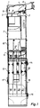
- FIG. 1 shows the frame 1 which is U-shaped in cross section, in which form the individual components of the coin system Modules are held.
- the frame 1 At the upper end of the frame 1 is angled in the Leg formed side panels in cross section approximately rectangular coin inlet tube piece forming the coin inlet channel 4 supported. This points to its front End a tongue 5 on which to mount it in a corresponding Slit of the side part 3 engages.
- the coin inlet pipe section 4 In its middle In the area, the coin inlet pipe section 4 has a hook 6 a beveled front edge, with which this in lock a corresponding recess in the side part 2 leaves. To remove the coin inlet pipe section 4, the Hook 6 to be pivoted only by hand, so that the Remove the tongue 5 from the holding slot in the side wall 3 leaves.
- the module containing the coin validator 7 Under the coin inlet is the module containing the coin validator 7 supported. To hold the module 7, this is with lateral Provide pegs in corresponding guides or bayonet-like Guides of the side parts 2, 3 of the frame 1 can be used are.
- the module 7 is in its inserted and locked Position held in the frame 1 so that its Inlet slot 8 below the outlet slot 9 of the coin inlet tube piece 4 lies.
- module 7 Under the module 7 is a module 10 in the side parts 2, 3 supported that with channels for forwarding the from the module 7 sorted coins is provided. Below module 10 there is a module 11 forming a coin pass. This is also with pins for mounting in the side parts 2, 3 provided. The module 10 is on its top with two Provide leaf springs 12 that move the module 10 upwards try.
- the module 13 is in the side parts 2, 3 held that the coin stacking tubes and the coin payout unit contains.
- the coin payout unit has exit openings provided the coins to be disbursed in one to the dispensing plate gives leadership.
- a flap 16 In the area of the module 13 is by hinges 14, 15 on the Side part 2 hinged a flap 16, the opposite End by a snap lock 17 on the side part 3 can be locked.
- the flap 16 covers the coin stacking tubes 18 to 21, so that unauthorized persons do not immediately fill the respective level can recognize.
- the flap 16 with provided a handle cutout 22 which can be engaged to pull the frame out of the housing and swing it out.
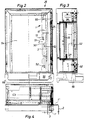
- Fig. 2 shows a front view of the from a flat box existing housing from which the front door is removed.
- the guide rails 26, 27 for the movable in this Carriage 28 attached.
- the guide rails and the slide are best seen in Figures 6 to 8.
- the guide rails 26, 27 consist of U-shaped profiles, the longer legs 28, 29 through elbows 30 on the housing side wall 24 are attached.
- the longer legs 28, 29 are provided with rows of holes 31 in which the gears 32 engage, on a synchronizing shaft mounted in the slide 33 34 are attached.
- the synchronizing shaft 34 carries on their pinions 32 protruding rollers 35, the are guided between the legs of the profiles 26, 27.
- By doing formed by an approximately rectangular cross-section housing Carriage 33 is also supported by a shaft 36 which is connected between the legs of the profiles 27, 28 engaging rollers 37 is.
- a roller 38 is mounted, those on the top edge of the outer shorter leg 39 of the guide rail 27 runs.
- the shorter leg 39 is in the end positions of the slide 33 provided with rounded recesses in the slight locking the roller 38 can occur.
- the housing 33 of the carriage has on its front, from the longer legs provided with the rows of holes 31 Bearing journals 40 facing away from the guide rails, 41 on, in the hinge eyes of the frame 1 can be hung.
- Fig. 4 is the frame pivotally mounted on the carriage 33 1 shown in three different positions, and in its fully retracted position 1, in its fully extended but not yet pivoted position 1 'and in its extended and swung out 90 degrees Position 1 '' in which the modules of the coin system held in this are easily accessible.
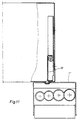
- the fully retracted position of the frame 1 is schematic shown in Fig. 10.
- the on the pivot pin 40, 41 of the Slide 33 are hinged eyelets 45 of the frame 1 itself in an embossed bead of the web parts 46 of the frame 1, at a distance from the inner side part 3 of the frame, which is about a third of the width of the web part 46 corresponds.
- the areas of the web part 46 support the slide lie on both sides of the joints 40, 41, 45, on the guide rails off so that the frame inside the case is held unmovable.
- the frame in the extended position of the slide 33 by 90 degrees swivel a position 1 '' in which the web part of the frame is at right angles in front of the side wall of the housing.
- Fig. 2 From Fig. 2 the inserted into the housing frame 1 in Side view shown.
- the edge areas of the side parts 2, 3 of the frame 1 are with free tapered slots 50 and provided with elongated holes with an inner, bayonet-like curvature 51, the bracket of the side pin inserted into the frame Serve modules.
- On the side part 2 are against each other Directional pin 52 is provided, which the pivot pin for the joints 14, 15 of the flap 16 form.
- levers 57, 58 are on the inside the wall 24 of the housing 54 two levers 57, 58 around pins 59, 60 pivotally mounted on their outward facing Provide ends with hooks 61, 62 projecting beyond the side wall 24 are.
- the levers 57, 58 are articulated with a coupling rod 63 connected, which runs parallel to the edge of the side wall 4 and connects the levers 57, 58 in such a way that these remain parallel to each other in every swivel position.
- the coupling rod 63 thus forms a four-bar system with the levers 57, 58.
- the lever 57 is with a over the hinge pin 59 extended lever arm 64 provided on the outer End of a tension spring 65 is suspended, the other end is attached to the housing.
- the spring 65 thus loads the Hooks 61, 62 towards the lower side of the housing.
- the hooks 61, 62 form the locks for the, not shown, hinged to the opposite housing side wall Door.
- the coupling rod 63 can be used to open the door a key raised by a lock, not shown become.
- the coupling rod has angled at its upper and lower ends Extensions 68, 69, whose lower edges 70, 71 beveled are. Lateral pins 72, 73 are on the slide 33 attached, when inserting the carriage 33 into the housing slide along the inclined surfaces 70, 71 of the extensions 68, 69 and thereby raise the coupling rod 63 until the front, the locking faces of the extensions 68, 69 interlocking behind the pins 72, 73. To the Slide 33 from its inserted and fixed position to solve, the coupling rod 63 must be raised.
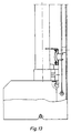
- 13 and 14 is a side view of the frame 1, partly in section, can be seen in the lower Area that the coin stacking tubes and the coin payout device containing module 13 is supported.
- a protective circuit board 80 attached, in a row with pairs arranged side by side, knife-like cutting 81 is provided, too can be formed by the legs of bow-like parts. These are arranged in pairs, knife-like Cutting edges 81 form contacts when the module is pivoted 13 in its position in the frame 1 come into contact with contact springs 82.
- the Contact springs 82 are held in one on the module 13 Plate 83 is attached such that it can be seen in FIG Dodge in the direction of the stacking tubes can, if they come into contact with the contact blades 81.
- the bow-like contact blades 81 close in the locked Position of the module 13, the contact springs 82 between their thighs so that a secure contact is guaranteed is.
- the entire power supply can take place via a plug 84, of the type shown in Fig. 20 in contact sockets is inserted, which is in the lower area of the circuit board 85 are located, in which the contact springs 82 are held are.
Landscapes
- Physics & Mathematics (AREA)
- General Physics & Mathematics (AREA)
- Slot Machines And Peripheral Devices (AREA)
- Pinball Game Machines (AREA)
- Control Of Vending Devices And Auxiliary Devices For Vending Devices (AREA)
- Developing Agents For Electrophotography (AREA)
- Silicon Polymers (AREA)
- Magnetic Record Carriers (AREA)
Description
- Fig. 1
- eine Vorderansicht der in einem Rahmen gehalterten Module der Münzanlage,
- Fig. 2
- eine Vorderansicht des Gehäuses des Geldspielgeräts bei entfernter Tür und mit in das Gehäuse eingefahrenem Rahmen, in dem keine Module der Münzanlage gehaltert sind,
- Fig. 3
- eine Draufsicht auf die den Rahmen halternden Seitenwand mit Schlitten und Schlittenführung,
- Fig. 4
- einen Querschnitt durch das Gehäuse nach den Figuren 2 und 3,
- Fig. 5
- eine vergrößerte Darstellung der Fig. 3,
- Fig. 6
- eine vergrößerte Darstellung des Schlittens mit Schlittenführung in einer Vorderansicht,
- Fig. 7
- die Darstellung nach Fig. 6 in Seitenansicht,
- Fig. 8
- einen Schnitt durch den Schlitten mit Schlittenführung nach Fig. 6,
- Fig. 9
- eine Darstellung der Schlittenführung unter Weglassung von die Übersichtlichkeit beeinträchtigenden Teilen,
- Fig. 10
- eine schematische Darstellung des in das Gehäuse eingeschobenen Rahmens, teilweise im Schnitt,
- Fig. 11
- eine der Fig. 10 entsprechende Darstellung mit aus dem Gehäuse ausgefahrenem und ausgeschwenktem Rahmen,
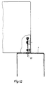
- Fig. 12
- eine Darstellung der Arretierung des Rahmens im ausgefahrenen und ausgeschwenkten Zustand,
- Fig. 13
- eine Seitenansicht des in dem Rahmen gehalterten, durch die Münzstapelrohre und die Münzauszahleinrichtung gebildeten Moduls mit der Kontaktierung der Leiterplatte, teilweise im Schnitt,
- Fig. 14
- eine der Fig. 13 entsprechende Darstellung während des Einhängens des die Münzstapelrohre und die Münzauszahleinrichtung enthaltenden Moduls,
- Fig. 15
- eine Seitenansicht des unteren Teils des Rahmens mit in diesem gehalterten Modulen des Münzdurchlaufs, der Münzstapelrohre und der Münzauszahleinrichtung,
- Fig. 16
- eine Vorderansicht des Rahmenteils nach Fig. 15,
- Fig. 17
- einen Schnitt durch das Rahmenteil nach Fig. 16,
- Fig. 18
- eine Rückansicht des durch die Münzstapelrohre und die Münzauszahleinrichtung gebildeten Moduls mit der Kontaktfederanordnung,
- Fig. 19
- einen Schnitt durch die Darstellung nach Fig. 18,
- Fig. 20
- eine Seitenansicht der Darstellung nach Fig. 18 und
- Fig. 21
- eine vergrößerte Darstellung der Fig. 19.
Claims (16)
- Geldspielgerätmit einem kastenförmigen Gehäuse und einer an einer Seitenwand angelenkten und mit dem Gehäuse verriegelbaren Tür, deren Außenseite Spielfeder und die das Spiel charakterisierende Gestaltung trägt,mit einer in dem Gehäuse angeordneten Münzanlage, bestehend mindestens aus Münzeinlaut Münzprüfer, Münzenverteiler- und Münzenleiteinrichtung, Münzstapelrohren und Münzauszahleinrichtung, undmit an der auf der Öffnungsseite der Tür befindlichen Seitenwand des Gehäuses befestigten Laufschienen für einen einen Rahmen halternden Schlitten, der mit Halteeinrichtungen für die einzelnen durch die Komponenten der Münzanlage gebildeten Module versehen ist,
dadurch gekennzeichnet,daß an der Innenseite der Rückwand des Rahmens (1) eine Leiterplatte (80) mit Kontakte bildenden, paarweise nebeneinander angeordneten messerartigen Schneiden (81) gehaltert ist, die beim Einsetzen eines mit Kontaktfedern (82) versehenen Moduls (13) in den Rahmen (1) in leitenden Kontakt mit diesen Kontaktfedern kommen. - Geldspielgerät nach Anspruch 1, dadurch gekennzeichnet, daß die paarweise nebeneinander angeordneten messerartigen Schneiden (81) durch die Schenkel von bügelartigen Teilen gebildet sind.
- Geldspielgerät nach Anspruch 1 oder 2, dadurch gekennzeichnet, daß das die Auszahleinrichtung und die Münzstapelrohre enthaltende Modul (13) mit Kontaktfedern versehen ist.
- Geldspielgerät nach einem der Ansprüche 1 bis 3, dadurch gekennzeichnet, daß die bügelförmigen Schenkel (81) und die Kontaktfedern (82) in einer Reihe angeordnet sind.
- Geldspielgerät nach einem der Ansprüche 1 bis 4, dadurch gekennzeichnet, daß die Kontaktfedern (82) aus vorgespannten Zugfedern bestehen.
- Geldspielgerät nach Anspruch 1, dadurch gekennzeichnet, daß die Module (7, 10, 11, 13) mit seitlichen Zapfen versehen sind, die in schlitz- und/oder bajonettartige Führungen (50, 51) den Seitenrändern der Seitenteile (2, 3) des Rahmens (1) einsetzbar sind.
- Geldspielgerät nach Anspruch 1, dadurch gekennzeichnet, daß zwei zueinander parallele Laufschienen vorgesehen sind, die mit Zahnleisten oder Lochreihen versehen sind, in die die Zähne zweier auf einer gemeinsamen, in dem Schlitten gelagerten Synchronisierwelle befestigten Zahnräder greifen.
- Geldspielgerät nach Anspruch 7, dadurch gekennzeichnet, daß die Schienen ein U-förmiges Profil besitzen und mit aufeinander zu gerichteten Schenkein montiert sind und daß die Lochreihen in den der Seitenwandung zugewandten Schenkeln der Laufschienen angeordnet sind.
- Geldspielgerät nach Anspruch 7 oder 8, dadurch gekennzeichnet, daß in dem Schlitten jeweils 2 zwischen die Schenkel jeder Schiene greifenden Rollen gelagert sind.
- Geldspielgerät nach einem der Ansprüche 7 bis 9, dadurch gekennzeichnet, daß sich der Schlitten mit einer Laufrolle auf dem oberen Rand des äußeren Schenkels der unteren Schiene abstützt.
- Geldspielgerät nach einem der Ansprüche 7 bis 10, dadurch gekennzeichnet, daß der Schlitten mit 2 fluchtenden, zu seiner Außenkante parallelen, aufragenden Zapfen versehen ist, an die Gelenkösen des Rahmens einsetzbar sind.
- Geldspielgerät nach einem der Ansprüche 7, bis 11, dadurch gekennzeichnet, daß der Rahmen aus einem U-förmig abgekanteten Blechzuschnitt besteht und sich die Gelenkösen auf der Außenseite des Stegteils in seitlichem Abstand von den die Seitenteile bildenden Schenkeln des Rahmens befinden.
- Geldspielgerät nach Anspruch 1, dadurch gekennzeichnet, daß an der Seitenwand des Gehäuses (1) parallel zueinander zwei mit Haken versehene Hebel schwenkbar gelagert sind, die durch eine eine Koppel bildende Verbindungsstange schwenkbar miteinander verbunden sind und die Verriegelungen für die Tür bilden.
- Geldspielgerät nach Anspruch 13, dadurch gekennzeichnet, daß das aus den beiden Hebeln und der Verbindungsstange bestehende Vier-Gelenk-System durch eine Feder in Richtung auf die Verriegelungsstellung beaufschlagt ist.
- Geldspielgerät nach Anspruch 13 oder 14, dadurch gekennzeichnet, daß die Verbindungsstange mit Schrägflächen versehene Verriegelungsstücke für den Rahmen in seiner eingeschobenen Stellung besitzt.
- Geldspielgerät nach einem der Ansprüche 13 bis 15, dadurch gekennzeichnet, daß die Verbindungsstange zur Entriegelung der Tür durch ein durch einen Schlüssel betätigbares Schloß anhebbar ist.
Priority Applications (1)
| Application Number | Priority Date | Filing Date | Title |
|---|---|---|---|
| EP98124031A EP0919966A3 (de) | 1993-11-11 | 1994-09-14 | Geldspielgerät |
Applications Claiming Priority (3)
| Application Number | Priority Date | Filing Date | Title |
|---|---|---|---|
| DE4338611 | 1993-11-11 | ||
| DE19934338611 DE4338611C2 (de) | 1993-11-11 | 1993-11-11 | Geldspielgerät |
| PCT/EP1994/003080 WO1995013598A1 (de) | 1993-11-11 | 1994-09-14 | Geldspielgerät |
Related Child Applications (1)
| Application Number | Title | Priority Date | Filing Date |
|---|---|---|---|
| EP98124031A Division EP0919966A3 (de) | 1993-11-11 | 1994-09-14 | Geldspielgerät |
Publications (2)
| Publication Number | Publication Date |
|---|---|
| EP0678209A1 EP0678209A1 (de) | 1995-10-25 |
| EP0678209B1 true EP0678209B1 (de) | 2000-03-29 |
Family
ID=6502408
Family Applications (2)
| Application Number | Title | Priority Date | Filing Date |
|---|---|---|---|
| EP98124031A Withdrawn EP0919966A3 (de) | 1993-11-11 | 1994-09-14 | Geldspielgerät |
| EP94926941A Expired - Lifetime EP0678209B1 (de) | 1993-11-11 | 1994-09-14 | Geldspielgerät |
Family Applications Before (1)
| Application Number | Title | Priority Date | Filing Date |
|---|---|---|---|
| EP98124031A Withdrawn EP0919966A3 (de) | 1993-11-11 | 1994-09-14 | Geldspielgerät |
Country Status (5)
| Country | Link |
|---|---|
| US (1) | US5662204A (de) |
| EP (2) | EP0919966A3 (de) |
| AT (1) | ATE191287T1 (de) |
| DE (3) | DE4345297A1 (de) |
| WO (1) | WO1995013598A1 (de) |
Families Citing this family (17)
| Publication number | Priority date | Publication date | Assignee | Title |
|---|---|---|---|---|
| JP3416475B2 (ja) * | 1997-08-07 | 2003-06-16 | コナミ株式会社 | ゲーム機の錠止装置 |
| ES2143383B1 (es) * | 1997-11-27 | 2000-12-01 | Arp Titular Al 50 Jurgen Joach | Mueble escamoteable para maquinas electronicas recreativas. |
| US5967287A (en) * | 1998-01-15 | 1999-10-19 | Cole; Joseph | Internally mounted, externally lockable and removable coin comparator mounting device for video vending machines and the like |
| AT406725B (de) * | 1998-02-24 | 2000-08-25 | Siemens Ag Oesterreich | Elektronisches gerät |
| GB2326964B (en) | 1998-03-23 | 1999-06-16 | Coin Controls | Coin changer |
| US6575541B1 (en) * | 2000-10-11 | 2003-06-10 | Igt | Translucent monitor masks, substrate and apparatus for removable attachment to gaming device cabinet |
| US6699128B1 (en) * | 2000-10-13 | 2004-03-02 | Igt | Manual lever with locking function for mounting CPU enclosure |
| US6556450B1 (en) * | 2002-04-08 | 2003-04-29 | Wms Gaming Inc. | Methods and apparatus of docking a gaming control board to an interface board in a gaming machine |
| US7381126B2 (en) * | 2003-11-03 | 2008-06-03 | Coin Acceptors, Inc. | Coin payout device |
| US20060178219A1 (en) * | 2005-01-21 | 2006-08-10 | Mallory Chester L | Cabinet for a gaming machine |
| DE102006039931A1 (de) * | 2006-08-25 | 2008-04-17 | Walter Hanke Mechanische Werkstätten GmbH & Co. KG | Hopper-Zwischenkasse |
| CN117980489A (zh) | 2021-07-14 | 2024-05-03 | 梅里特斯英国第二有限公司 | Retgc基因疗法 |
| WO2023285986A1 (en) | 2021-07-14 | 2023-01-19 | Meiragtx Uk Ii Limited | Kcnv2 gene therapy |
| WO2024079658A1 (en) | 2022-10-11 | 2024-04-18 | Meiragtx Uk Ii Limited | Bdnf gene therapy |
| JP2025535115A (ja) | 2022-10-11 | 2025-10-22 | メイラグティーエックス ユーケー アイアイ リミティド | Upf1発現構築物 |
| JP2025535114A (ja) | 2022-10-11 | 2025-10-22 | メイラグティーエックス ユーケー アイアイ リミティド | 中枢神経系における遺伝子発現のための核酸調節エレメント及び使用方法 |
| JP2025533994A (ja) | 2022-10-11 | 2025-10-09 | メイラグティーエックス ユーケー アイアイ リミティド | Atp7b遺伝子療法 |
Family Cites Families (10)
| Publication number | Priority date | Publication date | Assignee | Title |
|---|---|---|---|---|
| GB829664A (en) * | 1957-06-05 | 1960-03-02 | Emi Ltd | Improvements in or relating to the mounting of printed circuit panels |
| DE1259985B (de) * | 1964-09-30 | 1968-02-01 | Siemens Ag | Anordnung fuer Geraete der elektrischen Nachrichtentechnik und Messtechnik mit einerloesbaren Frontplatte |
| US3339995A (en) * | 1965-11-17 | 1967-09-05 | Weber Knapp Co | Console closure support |
| DE2530441A1 (de) * | 1975-07-08 | 1977-01-13 | Siemens Ag | Fernsprechgeraet |
| JPS639019Y2 (de) * | 1979-11-22 | 1988-03-17 | ||
| DE3434780A1 (de) * | 1984-09-21 | 1986-03-27 | Nixdorf Computer Ag, 4790 Paderborn | Blattabzugseinrichtung mit einer einsatz-kassette zur aufnahme eines blattstapels |
| DE3727927C2 (de) * | 1987-08-21 | 1996-07-25 | Paul Gauselmann | Münzeinheit für ein Unterhaltungsgerät |
| JPH0162684U (de) * | 1987-10-16 | 1989-04-21 | ||
| US5048663A (en) * | 1988-09-17 | 1991-09-17 | Asahi Seiko Kabushiki Kaisha | Electronic coin acceptor |
| GB2251329B (en) * | 1990-11-13 | 1994-06-01 | Electrocoin Automatics Limited | Coin-released amusement or gaming machines |
-
1993
- 1993-11-11 DE DE4345297A patent/DE4345297A1/de not_active Ceased
- 1993-11-11 DE DE4345296A patent/DE4345296C2/de not_active Expired - Lifetime
-
1994
- 1994-09-14 DE DE59409250T patent/DE59409250D1/de not_active Expired - Lifetime
- 1994-09-14 AT AT94926941T patent/ATE191287T1/de active
- 1994-09-14 WO PCT/EP1994/003080 patent/WO1995013598A1/de not_active Ceased
- 1994-09-14 US US08/481,523 patent/US5662204A/en not_active Expired - Fee Related
- 1994-09-14 EP EP98124031A patent/EP0919966A3/de not_active Withdrawn
- 1994-09-14 EP EP94926941A patent/EP0678209B1/de not_active Expired - Lifetime
Also Published As
| Publication number | Publication date |
|---|---|
| WO1995013598A1 (de) | 1995-05-18 |
| DE59409250D1 (de) | 2000-05-04 |
| DE4345296A1 (de) | 1995-09-28 |
| EP0678209A1 (de) | 1995-10-25 |
| ATE191287T1 (de) | 2000-04-15 |
| US5662204A (en) | 1997-09-02 |
| DE4345297A1 (de) | 1995-09-28 |
| DE4345296C2 (de) | 1996-08-22 |
| EP0919966A3 (de) | 2004-10-27 |
| EP0919966A2 (de) | 1999-06-02 |
Similar Documents
| Publication | Publication Date | Title |
|---|---|---|
| EP0678209B1 (de) | Geldspielgerät | |
| EP0072370B1 (de) | Geldschublade für Registrierkassen in Kassentischen, Verkaufstheken oder dergleichen | |
| DE4435932C2 (de) | Gargerät mit einer eine Frontöffnung verschließenden Tür | |
| EP3760387B1 (de) | Verschlusskasten | |
| DE3627120C1 (de) | Kassenlade | |
| DE4338611A1 (de) | Geldspielgerät | |
| DE3014277C2 (de) | Schubladenführung für die Geldschublade einer Registrierkasse in Kassentischen, Verkaufstheken o.dgl. | |
| DE60019285T2 (de) | Vorrichtung zum verglasen eines balkons | |
| DE3635352A1 (de) | Haltestelleninformationsstaender | |
| EP0698707B1 (de) | Zentralverriegelungseinrichtung für einen Werkzeugwagen | |
| EP0051719B1 (de) | Mechanischer Selbstverkäufer | |
| DE2237395A1 (de) | Glasschiebetuer, insbesondere fuer ganzglas-vitrinen | |
| EP0671522A1 (de) | Dachfenster | |
| DE20107066U1 (de) | Warentheke | |
| DE3235011A1 (de) | Muenzbetaetigtes bildschirm-spielgeraet | |
| EP3394840B1 (de) | Geldautomat | |
| DE69301583T2 (de) | Schiebetritt eines Nutzfahrzeuges mit Verriegelungseinrichtung | |
| DE2512426C3 (de) | Fahrzeugdach mit innerhalb einer Dachöffnung angeordnetem Deckel | |
| DE3102461C2 (de) | Selbstverkäufer | |
| DE4309305C1 (de) | Rollwagen für schwere Lasten | |
| DE29807572U1 (de) | Vorrichtung zum Sichern von Toren und Türen gegen Auf- und Zuschlagen | |
| EP0090068A1 (de) | Münzautomat für Zeitungen, Zeitschriften, Lebensmittel oder andere Waren | |
| DE2505671A1 (de) | Schaukasten | |
| DE2512426A1 (de) | Fahrzeugdach mit innerhalb einer dachoeffnung angeordnetem deckel | |
| DE29811122U1 (de) | Depositeinrichtung |
Legal Events
| Date | Code | Title | Description |
|---|---|---|---|
| PUAI | Public reference made under article 153(3) epc to a published international application that has entered the european phase |
Free format text: ORIGINAL CODE: 0009012 |
|
| 17P | Request for examination filed |
Effective date: 19950620 |
|
| AK | Designated contracting states |
Kind code of ref document: A1 Designated state(s): AT CH DE FR GB LI NL |
|
| 17Q | First examination report despatched |
Effective date: 19970627 |
|
| GRAG | Despatch of communication of intention to grant |
Free format text: ORIGINAL CODE: EPIDOS AGRA |
|
| GRAG | Despatch of communication of intention to grant |
Free format text: ORIGINAL CODE: EPIDOS AGRA |
|
| GRAG | Despatch of communication of intention to grant |
Free format text: ORIGINAL CODE: EPIDOS AGRA |
|
| GRAH | Despatch of communication of intention to grant a patent |
Free format text: ORIGINAL CODE: EPIDOS IGRA |
|
| GRAH | Despatch of communication of intention to grant a patent |
Free format text: ORIGINAL CODE: EPIDOS IGRA |
|
| GRAA | (expected) grant |
Free format text: ORIGINAL CODE: 0009210 |
|
| AK | Designated contracting states |
Kind code of ref document: B1 Designated state(s): AT CH DE FR GB LI NL |
|
| PG25 | Lapsed in a contracting state [announced via postgrant information from national office to epo] |
Ref country code: NL Free format text: LAPSE BECAUSE OF FAILURE TO SUBMIT A TRANSLATION OF THE DESCRIPTION OR TO PAY THE FEE WITHIN THE PRESCRIBED TIME-LIMIT Effective date: 20000329 Ref country code: GB Free format text: LAPSE BECAUSE OF FAILURE TO SUBMIT A TRANSLATION OF THE DESCRIPTION OR TO PAY THE FEE WITHIN THE PRESCRIBED TIME-LIMIT Effective date: 20000329 Ref country code: FR Free format text: LAPSE BECAUSE OF FAILURE TO SUBMIT A TRANSLATION OF THE DESCRIPTION OR TO PAY THE FEE WITHIN THE PRESCRIBED TIME-LIMIT Effective date: 20000329 |
|
| REF | Corresponds to: |
Ref document number: 191287 Country of ref document: AT Date of ref document: 20000415 Kind code of ref document: T |
|
| RIC1 | Information provided on ipc code assigned before grant |
Free format text: 7G 07F 9/10 A, 7G 07F 17/32 B, 7H 01R 12/20 B, 7H 05K 7/14 B |
|
| REG | Reference to a national code |
Ref country code: CH Ref legal event code: EP |
|
| REF | Corresponds to: |
Ref document number: 59409250 Country of ref document: DE Date of ref document: 20000504 |
|
| EN | Fr: translation not filed | ||
| NLV1 | Nl: lapsed or annulled due to failure to fulfill the requirements of art. 29p and 29m of the patents act | ||
| PG25 | Lapsed in a contracting state [announced via postgrant information from national office to epo] |
Ref country code: AT Free format text: LAPSE BECAUSE OF NON-PAYMENT OF DUE FEES Effective date: 20000914 |
|
| GBV | Gb: ep patent (uk) treated as always having been void in accordance with gb section 77(7)/1977 [no translation filed] |
Effective date: 20000329 |
|
| PG25 | Lapsed in a contracting state [announced via postgrant information from national office to epo] |
Ref country code: LI Free format text: LAPSE BECAUSE OF NON-PAYMENT OF DUE FEES Effective date: 20000930 Ref country code: CH Free format text: LAPSE BECAUSE OF NON-PAYMENT OF DUE FEES Effective date: 20000930 |
|
| PLBE | No opposition filed within time limit |
Free format text: ORIGINAL CODE: 0009261 |
|
| STAA | Information on the status of an ep patent application or granted ep patent |
Free format text: STATUS: NO OPPOSITION FILED WITHIN TIME LIMIT |
|
| 26N | No opposition filed | ||
| REG | Reference to a national code |
Ref country code: CH Ref legal event code: PL |
|
| PGFP | Annual fee paid to national office [announced via postgrant information from national office to epo] |
Ref country code: DE Payment date: 20131009 Year of fee payment: 20 |
|
| REG | Reference to a national code |
Ref country code: DE Ref legal event code: R071 Ref document number: 59409250 Country of ref document: DE |
|
| PG25 | Lapsed in a contracting state [announced via postgrant information from national office to epo] |
Ref country code: DE Free format text: LAPSE BECAUSE OF EXPIRATION OF PROTECTION Effective date: 20140916 |