EP0678233A1 - Appareil de dosage pour distributeur - Google Patents
Appareil de dosage pour distributeur Download PDFInfo
- Publication number
- EP0678233A1 EP0678233A1 EP95104599A EP95104599A EP0678233A1 EP 0678233 A1 EP0678233 A1 EP 0678233A1 EP 95104599 A EP95104599 A EP 95104599A EP 95104599 A EP95104599 A EP 95104599A EP 0678233 A1 EP0678233 A1 EP 0678233A1
- Authority
- EP
- European Patent Office
- Prior art keywords
- metering
- wheels
- wheel
- coarse
- normal
- Prior art date
- Legal status (The legal status is an assumption and is not a legal conclusion. Google has not performed a legal analysis and makes no representation as to the accuracy of the status listed.)
- Granted
Links
Images





Classifications
-
- A—HUMAN NECESSITIES
- A01—AGRICULTURE; FORESTRY; ANIMAL HUSBANDRY; HUNTING; TRAPPING; FISHING
- A01C—PLANTING; SOWING; FERTILISING
- A01C7/00—Sowing
- A01C7/08—Broadcast seeders; Seeders depositing seeds in rows
- A01C7/087—Tramlining
-
- A—HUMAN NECESSITIES
- A01—AGRICULTURE; FORESTRY; ANIMAL HUSBANDRY; HUNTING; TRAPPING; FISHING
- A01C—PLANTING; SOWING; FERTILISING
- A01C7/00—Sowing
- A01C7/08—Broadcast seeders; Seeders depositing seeds in rows
- A01C7/12—Seeders with feeding wheels
- A01C7/123—Housings for feed rollers or wheels
- A01C7/125—Housings for feed rollers or wheels with bottom delivery of the seeds
Definitions
- the invention relates to a metering device for a distributor, such as a seeder and fertilizer spreader.
- This metering device is intended for a distribution machine, such as a seed drill or fertilizer spreader.
- This metering device is arranged under the lower area of a storage container.
- the metering device consists of a coarse or normal metering wheel and two fine metering wheels, which are rotatably mounted in a metering housing and can be driven by means of a metering shaft.
- These metering wheels can be coupled to the metering shaft using coupling elements.
- the coupling elements are designed in the form of a polygonal profile, which extend over a predetermined axial area of the metering shaft.
- This coupling elements are moved by moving the metering shafts in the axial direction relative to the metering wheels and the metering housing, so that the coupling element can optionally be brought into engagement with the metering wheels.
- This metering device has a single coarse metering wheel and fine metering wheels arranged on both sides of the metering wheel. In one position of the metering shaft, one fine metering wheel is coupled to the metering shaft. If the metering shaft is moved further, the second fine metering wheel is coupled to the metering shaft so that both fine metering wheels spread seed.
- the two fine metering wheels are uncoupled from the drive from the metering shaft and the metering shaft is non-positively connected only to the coarse metering wheel.
- the two fine metering wheels are staggered with respect to their cells, but are completely identical.
- the metering volume of the two fine metering wheels is the same.
- the sealing element formed by angling the base plate is arranged below the metering wheels. It has been shown that when the coarse or normal metering wheel is stopped, rapeseed grains, for example, which are only applied with one or both fine metering wheels, pass through the metering cell of the coarse or normal metering wheel into the delivery line in an undesirable manner via the upper edge of the sealing element.
- the invention has for its object to provide an improved metering device.
- a solution for the simple mounting of the metering shaft and the simple optional connection and disconnection of the coarse or metering wheels and the fine metering wheel is achieved by the characterizing features of claim 1.
- an axially fixed metering shaft can be used and the coupling elements are arranged in the freely accessible area outside the metering wheels and the metering housing, so that simple actuation of the coupling elements and simple checking of the coupling or uncoupling of the metering wheels can be carried out.
- a simple arrangement is achieved in that the metering wheels are arranged on hollow shafts arranged on the metering shaft.
- at least one further hollow shaft driving at least one metering wheel is arranged on at least one of the hollow shafts.
- Adequate and simple stepwise switching on or off of the metering wheels is achieved in that at least one metering wheel is connected in a rotationally fixed manner to a hollow shaft, and in that the hollow shafts can each be coupled to the metering shaft by means of at least one coupling element.
- the coupling elements are each designed such that in one position the coupling element has the metering wheel couples with the metering shaft and in the other position the coupling element stops the metering wheel relative to the housing in the uncoupled state.
- each metering wheel consists of at least two adjoining metering disks, which are rotatably connected to one another to form a metering wheel. This also creates the possibility that the cells of a metering wheel are offset by the amount that is formed from the product cell arc length divided by the number of metering disks. As a result of this measure, there is a very continuous and uniform conveying of the material from the storage container via the metering wheels into the delivery line.
- the individual metering wheels are easily interchangeable with another metering wheel having a different shape or a different delivery volume.
- one of the two coarse or normal metering wheels has a larger metering volume than the other coarse or normal metering wheel.
- the coarse or normal metering wheel having the larger metering volume can advantageously be used to apply corn, beans, peas, etc.
- two coarse or normal metering wheels are provided in such a way that one or both coarse or normal metering wheels can optionally be coupled to the metering shaft.
- the different metering volumes of the coarse or normal metering wheels or fine metering wheels can be achieved by providing metering wheels of different widths or metering cells of different depths.
- the simple exchange of the metering wheels can be achieved in that at least one of the side walls of the metering housing with the coupling element is removably arranged on the metering housing.
- the metering device has an agitator shaft above the metering wheels, that the agitator shaft can be driven by the metering shaft via a spur gear drive.
- This simple drive is particularly easy to achieve by the axially fixed metering shaft. This results in a very simple drive for the metering unit and also for the agitator shaft itself.
- the agitator shaft or the metering shaft can be driven from one side or the other of the metering device with a drive, starting from a continuously variable transmission which is in front of a power source, for example one driven on a floor rolling drive wheel, be coupled.
- the metering wheels each have axially extending cells on their outer surface, and at least one sealing element sealing the housing against the metering wheels is arranged in the lower region of the metering wheels, the sealing element having a length as seen in the conveying direction which is at least corresponds to the radian measure of the cells on their outer edge.
- a cell web located between the cells of the metering wheel cooperates sealingly with the sealing lip. It is advantageous here if the cell web at least partially overlaps with the sealing lip. For this purpose, it can be provided that the cell web is at least partially overlapping the sealing lip. In the case of metering devices which have a plurality of metering wheels which can be switched off, it is provided that the webs can be fixed at least approximately in alignment with one another in the switched-off and fixed position of the metering wheels.
- the coarse or normal metering wheels have a greater division than the fine metering wheels, so that there are more metering cells in the fine metering wheel than in the coarse or normal metering wheel.
- An advantageous seal can be achieved in that the sealing element has a greater width in the area of the coarse or normal metering wheels than in the area of the fine metering wheels.
- the same with regard to the avoidance of incorrect metering due to undesired leakage of seed through the metering cells of shutdown metering wheels can be achieved in that the metering wheels are fixed in defined positions by stop elements in such a way that the webs separating the metering cells from one another directly or immediately Proximity of the sealing element can be fixed or held so that no material can escape through the metering cells.
- an emptying flap or slide is arranged below the metering wheels in the metering housing.
- the metering device is arranged in the lower region of a storage container which has an outlet funnel, and that with larger working widths the storage container has at least two outlet funnels with two metering devices.
- a remote control device is arranged on the metering device, by means of which the application rate can be adjusted and / or changed.
- the metering device in a seeder which has a tramline circuit is adjusted such that when the tramline is created, the seed quantity is increased by the seed quantity supplied to the tramline coulters is reduced.
- the fine metering wheels are arranged on one side and the coarse or normal metering wheels are arranged on the other side of the metering device.
- disks or disk-like elements are arranged between the metering wheels, which can be switched on and off separately, which separate the cells of the individual metering wheels.
- the storage container being divided into at least two outlet funnels in its lower region, with a metering device being arranged below each outlet funnel, that the storage container is at least two, preferably has four discharge funnels, each of which a metering device is assigned, and that the metering device convey the metered material into pneumatic feed lines which lead to a central conveyor line with a distributor head, at the outlets of which are connected to material discharge elements such as seed coulters.
- the storage container prefferably has three, preferably four discharge funnels, each of which is assigned a metering device which introduces the metered material into conveying lines leading to baffle heads, two metering devices being assigned to one baffle head. Even with machines with large working widths that have multiple impact heads, a flat and large capacity storage container can be achieved.
- the storage container 1 and 2 has the storage container 1, the frame 2 and the coulters 3 hinged to the frame 2.
- the material in the storage container is fed via the metering device 4 via a lock into the delivery line 6 connected to the blower 5.
- the metered material reaches the distributor designed as a baffle head 7, from which the seed is divided into the individual outlets 8, to which the lines 9 leading to the coulters 3 are connected.
- the reservoir 10 of the distributor is divided into the two outlet funnels 12 by the roof-shaped central part 11.
- the metering device 4 with the delivery line 6, which is also connected to a blower 5, is arranged below each outlet funnel 12.
- Each delivery line 6 leads to a distributor 7.
- the reservoir 13 has four outlet funnels 14, each with a metering device 4. All delivery lines 6 open into a connector 15, which combines the delivery lines 6 and leads to a riser pipe 16. The material dosed by all dosing devices 4 reaches the distributor head 7, where it is then distributed to the individual outlets 8. Due to this design of the storage container 13 with four outlet funnels 14, the storage container 13 is built relatively low even with a large capacity.
- the reservoir 13 has a width of about 3 m in its upper area, so that it can still be transported on public roads and paths.
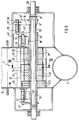
- FIGS. 6 and 7 show the metering device 4, which is arranged below the storage containers 1, 10, 13.
- the metering device 4 according to FIGS. 6 and 7 is provided for a seeder or a fertilizer spreader.
- Each metering device 4 has a metering housing 18.
- the metering housing 18 is fastened to the connecting flanges 19 of the storage container 1.
- the metering shaft 20 is mounted in the metering housing 18.
- the two coarse or normal metering wheels 21 and 22 and a fine metering wheel 23 are arranged in the housing 18 on the metering shaft 20.
- the driven stirring shaft 24 with stirring elements is arranged in the metering housing 18.
- the hollow shaft 25 guided out of the housing 18, on which the coarse or normal metering wheel 21 is located is arranged.
- the coarse or normal metering wheel 21 is arranged in a rotationally fixed manner via the wedge connection 26 and is designed to be non-rotatable.
- the coarse or normal metering wheel consists of three metering disks 27, the metering disks 27 have metering cells 28.
- the cells 28 of the metering disks 27 of a metering wheel 21 are offset from one another by the amount which is formed from the product cell arc length divided by the number of metering disks 21, so that continuous and uniform conveying is achieved.
- a further hollow shaft 29 Arranged on the hollow shaft 25 is a further hollow shaft 29 which leads out of the housing 18 and on which the coarse or normal metering wheel 22 is arranged in a rotationally fixed manner by means of the connection designed as a wedge connection 26. Furthermore, the hollow shaft 30 is arranged on the metering shaft 20, on which the metering disks 31 of the fine metering wheel 23 are arranged by means of the wedge connection 26.
- a socket 32 with the connecting pin 33 is arranged in a rotationally fixed manner outside the housing 18.
- the driver lever 34 is attached outside the housing 18 and carries the displaceable coupling pin 36 at its outer end 35.
- the coupling pin 36 is in the position shown by solid lines, the hollow shaft 25 and thus the metering wheel 21 is carried along via the driving lever 34 'and the coupling pin 36, so that via the metering shaft 20, the adjustable and not shown control gear from a power source, for example one on the ground rolling drive wheel is driven, the metering wheel 21 is driven so that the coarse and normal metering wheel 21, the material located in the reservoir 1 is introduced into the delivery line 6 via a lock.
- the coupling pin 37 grips behind the stop 39, so that it is ensured that the normal and coarse metering wheel 22 is not rotating, but is safely stopped, so that there is no incorrect metering .
- the length of the bolts 36, 37 and 41 is chosen so that, in no case, in an intermediate position of the bolts 36, 37 and 41, does it at the same time behind the stop element 39, 41 and the driving element 33, 34, 40 so that any risk of breakage is excluded.
- the bolts 36, 37 and 41 designed as coupling elements are arranged outside the metering wheels and the housing in a clearly visible and accessible area, so that the bolts can be easily switched or actuated.
- the bolt 36 is pushed into the position 36 'shown in broken lines so that the drive is uncoupled.
- the bolt 36 is in the dashed position 36 ', the two normal and coarse metering wheels 21, 22 are uncoupled from the drive by the metering shaft 20 at the same time.
- the pin 36 grips behind the stop 43 and thus an undesired rotation of the normal or coarse metering wheels 21 and 22 is reliably avoided.
- an element 44 Arranged above the metering wheels 21, 22 and 23 on the metering housing 18 is an element 44 sealing the metering housing 18 against the metering wheels 21, 22 and 23, which is designed as a bristle element.
- sealing element 45 which seals the metering housing 18 against the metering wheels 21, 22 and 23.
- This sealing element 45 has a length, as seen in the conveying direction 46, which is at least the radian measure of the cell 28 whose outer edge corresponds.
- the sealing element consists of an elastic rubber or plastic material, such as foam rubber.
- the residual emptying opening 48 In the lower area 47 of the metering housing 18 there is the residual emptying opening 48, which can be opened by a slide 49 or one of the positions shown is closed by the slide 49.
- a cleaning element 50 such as, for example, claws, cleaning brush, cleaning wool, scratching elements, etc., can be arranged above the metering wheels 23 outside the metering housing 18 in order to clean the cells 28 of materials adhering to or in the cells.
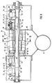
- the structure of the metering device 51 according to FIG. 8 corresponds in principle to the metering device 4 according to FIG. 8, but with the difference that two fine metering wheels 52 and 53 are provided and that the coupling elements between the metering shaft 20 and the hollow shafts are designed differently. These coupling elements are also arranged outside the metering wheels and the metering housing.
- the hollow shaft 25 is arranged on the metering shaft 20.
- the metering disks 54 of the normal or coarse metering wheel 55 are located on the hollow shaft 25 in a rotationally fixed arrangement.
- the dosing cells 58 des The normal and coarse metering wheel 55 are larger than the metering cells 59 of the normal and coarse metering wheel 57.
- the socket 32 with the driving element 34 ' is arranged in a rotationally fixed manner by means of the bolt 33.
- This driving element 34 ' can be taken along with the driving pin 36, which is displaceably guided on the driving element 34 arranged on the hollow shaft 25.
- the coarse and normal metering wheel 55 is rotatably coupled to the metering shaft 25.
- the driving element 38 is fastened with the displaceable bolt 37, which interacts with that on the driving element 34, which is arranged on the hollow shaft 25, via the displaceable coupling bolt 37.
- the bolt 37 grips behind the stop element 39 arranged on the metering housing 18 and stops the normal and coarse metering wheel 57. If the bolt 37 is displaced into the position 37 ′ shown with dashed lines, the coarse or normal metering wheel 57 is coupled in a rotationally fixed manner to the metering shaft 20 via the hollow shaft 25.
- the hollow shaft 62 led out of the housing 18 is also arranged, on which the fine metering wheel 52, which is designed as a fine metering wheel, is arranged in a rotationally fixed manner.
- the further hollow shaft 63 which is led out of the housing and on which the fine metering wheel 53 is arranged in a rotationally fixed manner.
- the hollow shaft 62 and the very fine metering wheel 53 are rotatably coupled to the metering shaft 20 via the coupling bolt 64 and the driving element 65.
- the fine metering wheel 53 is also connected in a rotationally fixed manner to the driving element 67 via a coupling bolt 66 and the hollow shaft to the metering shaft 20.
- the switching ranges and switching position of the bolts 36, 37, 64 and 68 are color coded differently at the points 71 so that it can easily be determined which metering wheels are connected to the metering shaft 20 in a rotationally fixed manner.
- the metering cells 68 of the very fine metering wheel 52 have a smaller metering volume than the metering cells 69 of the fine metering wheel 53.
- separating disk 70 Between the coarse or normal metering wheel 57 and the coarse metering wheel there is a separating disk 70, which can also be integrally connected to the outer disks of the metering wheels 55 and / or 57. Separating disks 70 are also arranged between the normal or coarse metering wheel 55 and the fine metering wheel 52 and the fine metering wheel 52 and the fine metering wheel 53.
- the lower wall 72 of the metering housing 18 opposite the metering wheels is formed obliquely.
- the outlet opening 48 for emptying residual quantities which is closed by the slide 49.
- the dosing device 51 'according to FIG. 10 differs from the dosing device 51 according to FIG. 9 by the narrower design of the sealing element 45'.
- the sealing element 45 ' is made of an elastic rubber or plastic material. So that a secure seal is ensured by the sealing element 45 'against the webs 73 separating the metering cells when the metering wheels are shut down so that no material undesirably gets into the feed line 6, the stop elements 39, 43 are arranged such that in the case of the shutdown metering wheels in any case there is a web 73 of the respectively shut down metering wheel directly on or in the immediate vicinity so that no material can escape through the cells.
- Stops or recesses can be arranged on the metering housing 18 or the bracket 61, which prevent the undesired rotation of the uncoupled metering wheels. Stop elements thus ensure that the switched-off metering wheels are stopped or fixed in such a position that a cell web 73 located between the cells of the metering wheel cooperates sealingly with the sealing lip 45 '. 10, the cell web 73 partially overlaps with the sealing lip 45 '. Furthermore, the stops are arranged in such a way that the cell webs 73 of the switched-off metering wheels can be fixed at least approximately in alignment with one another.
- the sealing element 45 or 45 ' is designed to be continuous over the entire width of the metering device.
- the displaceable gear wheel 74 is arranged on the metering shaft 20.
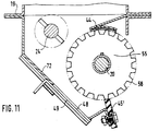
- This gear 74 is in the position shown by solid lines with the gear 75, which is rotatably arranged on the agitator shaft 24, in drive connection, so that via the metering shaft 20 and the spur gear 76, which is formed by the two gears 74 and 75, the agitator shaft 24 of the metering device 4 is driven. If it is not desired that the agitator shaft 24 is driven, the gear 74 can be moved and set in the position 74 'shown in broken lines, so that the drive connection between the two gears 74 and 75 or between the metering shaft 20 and the Stirring shaft 24 is interrupted. If, as shown in FIG.
- two metering devices 4 are arranged under a storage container, each of which has a stirring shaft 24, then according to the exemplary embodiment according to FIG. 11, these two stirring shafts 24 are connected to one another in a rotationally fixed manner via a connecting hollow shaft 77.
- the metering shafts 20 are driven via a control gear, not shown, which is driven by a power source, via the chain drives 78 and 79 or the chain drive 80.
- a drive speed reduction of the metering wheels is provided, so that when the tramlines are created, when some seed lines are blocked by the distributor head assigned to the metering device 4, the amount applied per seed is kept the same when the tramlines are created.
- the chain drive 78 is uncoupled from the metering shaft 20 via an actuating element (not shown).
- the metering shaft 20 is then driven via the chain drive 79 of the transmission drive 81.
- a freewheel is arranged between the chain wheel 82 of the transmission drive 81 and the metering shaft 80.
- the transmission ratio of the chain drive 78 is 1: 1, while the transmission ratio of the transmission drive 81 formed by the chain drive 79 is the ratio Total number of coulters per metering device to the total number of coulters per metering device minus tramline coulters per metering device ".
- the actuating element is coupled to the tramline switching device, also not shown, so that the transmission drive 79 is automatically switched on and the chain drive 78 is switched off
- the metering shaft of the other metering element 4 is driven at unchanged speed via the chain drive 80, because no tramline coulters are assigned to the distributor head assigned to this metering device 4.
- the two metering shafts 20 are connected to one another via the connecting bushing 82, so that the metering wheels of the two metering devices 4 are driven at the same speed.
- the gear wheels of the chain drives 78 and 79 are arranged on the connecting bushing 82. These chain drives can be used to reduce the amount of seed when the tramlines are being created, which is applied by the metering devices. This is done as described in the embodiment of FIG. 12.
- the two metering shafts 20 are connected to one another in a rotationally fixed manner with the connecting bushing 82.
- the chain drive 80 which is connected in a rotationally fixed manner to the metering shaft 20, the metering shafts 20 and thus the metering wheels of the metering devices 4 are driven by a power source.
Landscapes
- Life Sciences & Earth Sciences (AREA)
- Soil Sciences (AREA)
- Environmental Sciences (AREA)
- Fertilizing (AREA)
- External Artificial Organs (AREA)
- Electrical Discharge Machining, Electrochemical Machining, And Combined Machining (AREA)
- Sowing (AREA)
Priority Applications (2)
| Application Number | Priority Date | Filing Date | Title |
|---|---|---|---|
| EP99106896A EP0927511A3 (fr) | 1994-04-21 | 1995-03-29 | Appareil de dosage pour distributeur |
| DE29521979U DE29521979U1 (de) | 1994-04-21 | 1995-03-29 | Dosiervorrichtung für eine Verteilmaschine |
Applications Claiming Priority (8)
| Application Number | Priority Date | Filing Date | Title |
|---|---|---|---|
| DE4413856 | 1994-04-21 | ||
| DE4413856 | 1994-04-21 | ||
| DE4415603A DE4415603A1 (de) | 1994-04-21 | 1994-05-04 | Dosiervorrichtung für eine Verteilmaschine |
| DE4415603 | 1994-05-04 | ||
| DE4421842 | 1994-06-22 | ||
| DE4421842 | 1994-06-22 | ||
| DE4445313A DE4445313A1 (de) | 1994-04-21 | 1994-12-19 | Dosiervorrichtung für eine Verteilmaschine |
| DE4445313 | 1994-12-19 |
Related Child Applications (1)
| Application Number | Title | Priority Date | Filing Date |
|---|---|---|---|
| EP99106896A Division EP0927511A3 (fr) | 1994-04-21 | 1995-03-29 | Appareil de dosage pour distributeur |
Publications (2)
| Publication Number | Publication Date |
|---|---|
| EP0678233A1 true EP0678233A1 (fr) | 1995-10-25 |
| EP0678233B1 EP0678233B1 (fr) | 2000-05-24 |
Family
ID=27435954
Family Applications (1)
| Application Number | Title | Priority Date | Filing Date |
|---|---|---|---|
| EP95104599A Expired - Lifetime EP0678233B1 (fr) | 1994-04-21 | 1995-03-29 | Appareil de dosage pour distributeur |
Country Status (4)
| Country | Link |
|---|---|
| EP (1) | EP0678233B1 (fr) |
| CZ (1) | CZ288870B6 (fr) |
| DE (1) | DE29521716U1 (fr) |
| DK (1) | DK0678233T3 (fr) |
Cited By (7)
| Publication number | Priority date | Publication date | Assignee | Title |
|---|---|---|---|---|
| EP0898863A1 (fr) * | 1997-08-18 | 1999-03-03 | Deere & Company | Système de mesure pour une machine à semer avec au moins une roue de mesure |
| EP0898864A1 (fr) * | 1997-08-18 | 1999-03-03 | Deere & Company | Système de mesure pour une semoir pneumatique avec au moins une roue de mesure |
| WO2003077635A3 (fr) * | 2002-03-15 | 2003-12-18 | Finn Corp | Systeme d'evacuation de matieres en vrac, muni d'un dispositif d'alimentation |
| EP1430761B2 (fr) † | 2002-12-16 | 2012-04-11 | Kuhn S.A. | Mécanisme de dosage pour un semoir pouvant distribuer plusieurs produits simultanément |
| WO2022200372A1 (fr) * | 2021-03-22 | 2022-09-29 | Grimme Landmaschinenfabrik Gmbh & Co. Kg | Dispositif d'épandage agricole |
| EP4302585A1 (fr) * | 2022-07-08 | 2024-01-10 | RAUCH Landmaschinenfabrik GmbH | Unité de dosage pour produit à distribuer en poudre ou en particules et machine de distribution dotée d'une telle unité de dosage |
| EP4501095A1 (fr) * | 2023-08-02 | 2025-02-05 | Dennis Pülscher | Dispositif portable de dosage et de distribution |
Families Citing this family (2)
| Publication number | Priority date | Publication date | Assignee | Title |
|---|---|---|---|---|
| CN104541699B (zh) * | 2015-01-30 | 2017-03-01 | 刘继泽 | 一种防伤种型精量排种器 |
| DE102021126671A1 (de) * | 2021-10-14 | 2023-04-20 | Horsch Maschinen Gmbh | Dosiersystem für landwirtschaftliche Verteilmaschine und Verteilmaschine mit derartigem Dosiersystem |
Citations (6)
| Publication number | Priority date | Publication date | Assignee | Title |
|---|---|---|---|---|
| FR1563965A (fr) * | 1968-03-04 | 1969-04-18 | ||
| FR2481875A1 (fr) * | 1980-05-07 | 1981-11-13 | Kirchberger Franz | Systeme de commande pour semoirs |
| EP0209063A2 (fr) * | 1985-07-13 | 1987-01-21 | A.J. Tröster GmbH + Co KG | Semoir |
| DE3809592A1 (de) * | 1987-03-25 | 1988-10-06 | Bauer & Co Gmbh Reform Werke | Saemaschine |
| AT387129B (de) * | 1986-10-10 | 1988-12-12 | Karl Prillinger Landmaschinen | Saemaschine |
| EP0379231A2 (fr) * | 1985-10-15 | 1990-07-25 | Amazonen-Werke H. Dreyer GmbH & Co. KG | Epandeur d'engrais pneumatique |
-
1995
- 1995-03-29 DE DE29521716U patent/DE29521716U1/de not_active Expired - Lifetime
- 1995-03-29 DK DK95104599T patent/DK0678233T3/da active
- 1995-03-29 EP EP95104599A patent/EP0678233B1/fr not_active Expired - Lifetime
- 1995-04-18 CZ CZ1995984A patent/CZ288870B6/cs not_active IP Right Cessation
Patent Citations (6)
| Publication number | Priority date | Publication date | Assignee | Title |
|---|---|---|---|---|
| FR1563965A (fr) * | 1968-03-04 | 1969-04-18 | ||
| FR2481875A1 (fr) * | 1980-05-07 | 1981-11-13 | Kirchberger Franz | Systeme de commande pour semoirs |
| EP0209063A2 (fr) * | 1985-07-13 | 1987-01-21 | A.J. Tröster GmbH + Co KG | Semoir |
| EP0379231A2 (fr) * | 1985-10-15 | 1990-07-25 | Amazonen-Werke H. Dreyer GmbH & Co. KG | Epandeur d'engrais pneumatique |
| AT387129B (de) * | 1986-10-10 | 1988-12-12 | Karl Prillinger Landmaschinen | Saemaschine |
| DE3809592A1 (de) * | 1987-03-25 | 1988-10-06 | Bauer & Co Gmbh Reform Werke | Saemaschine |
Cited By (11)
| Publication number | Priority date | Publication date | Assignee | Title |
|---|---|---|---|---|
| EP0898863A1 (fr) * | 1997-08-18 | 1999-03-03 | Deere & Company | Système de mesure pour une machine à semer avec au moins une roue de mesure |
| EP0898864A1 (fr) * | 1997-08-18 | 1999-03-03 | Deere & Company | Système de mesure pour une semoir pneumatique avec au moins une roue de mesure |
| AU737278B2 (en) * | 1997-08-18 | 2001-08-16 | Deere & Company | Wear insert for metering system |
| AU737275B2 (en) * | 1997-08-18 | 2001-08-16 | Deere & Company | Brush for air seeder metering system |
| WO2003077635A3 (fr) * | 2002-03-15 | 2003-12-18 | Finn Corp | Systeme d'evacuation de matieres en vrac, muni d'un dispositif d'alimentation |
| US7083069B2 (en) | 2002-03-15 | 2006-08-01 | Finn Corporation | Bulk material discharge assembly with feeding apparatus |
| EP1430761B2 (fr) † | 2002-12-16 | 2012-04-11 | Kuhn S.A. | Mécanisme de dosage pour un semoir pouvant distribuer plusieurs produits simultanément |
| WO2022200372A1 (fr) * | 2021-03-22 | 2022-09-29 | Grimme Landmaschinenfabrik Gmbh & Co. Kg | Dispositif d'épandage agricole |
| CN117135999A (zh) * | 2021-03-22 | 2023-11-28 | 格立莫农业机械制造有限两合公司 | 农业播撒设备 |
| EP4302585A1 (fr) * | 2022-07-08 | 2024-01-10 | RAUCH Landmaschinenfabrik GmbH | Unité de dosage pour produit à distribuer en poudre ou en particules et machine de distribution dotée d'une telle unité de dosage |
| EP4501095A1 (fr) * | 2023-08-02 | 2025-02-05 | Dennis Pülscher | Dispositif portable de dosage et de distribution |
Also Published As
| Publication number | Publication date |
|---|---|
| CZ288870B6 (cs) | 2001-09-12 |
| DK0678233T3 (da) | 2000-08-07 |
| DE29521716U1 (de) | 1998-06-10 |
| CZ98495A3 (en) | 1995-11-15 |
| EP0678233B1 (fr) | 2000-05-24 |
Similar Documents
| Publication | Publication Date | Title |
|---|---|---|
| EP0897660B2 (fr) | Sectionneur de produit pour interrompre le flux du produit entre un reservoir et un système de mesure | |
| EP0898865B1 (fr) | Système de mesure pour une machine à semer, en particulier pneumatique | |
| EP1003359B1 (fr) | Systeme de distribution d'un dispositif d'ensemencement | |
| EP0898864B1 (fr) | Semoir pneumatique avec une système de mesure pour et au moins une roue de mesure | |
| EP1003360B1 (fr) | Systeme doseur d'un semoir | |
| EP0898861B1 (fr) | Semoir | |
| EP0833557B1 (fr) | Dispositif de semence avec doseur modulaire | |
| EP0898863B1 (fr) | Système de mesure pour une machine à semer avec au moins une roue de mesure | |
| EP0358878B1 (fr) | Dispositif doseur pour une machine à distribuer | |
| EP3840562A1 (fr) | Unité de dosage pour matière à distribuer pulvérulente ou particulaire et machine de distribution comprenant une telle unité de dosage | |
| DE4445313A1 (de) | Dosiervorrichtung für eine Verteilmaschine | |
| EP0678233B1 (fr) | Appareil de dosage pour distributeur | |
| DE3429817A1 (de) | Maschine zum ausbringen von saatgut und duengemitteln | |
| DE1457753A1 (de) | Streuvorrichtung zum Streuen dosierter Mengen | |
| DE2460869A1 (de) | Saemaschine | |
| DE4415603A1 (de) | Dosiervorrichtung für eine Verteilmaschine | |
| EP4302585A1 (fr) | Unité de dosage pour produit à distribuer en poudre ou en particules et machine de distribution dotée d'une telle unité de dosage | |
| EP0313995A1 (fr) | Epandeur, spécialement épandeur d'engrais centrifuge | |
| DE29521979U1 (de) | Dosiervorrichtung für eine Verteilmaschine | |
| DE3616538C2 (fr) | ||
| DE10010347A1 (de) | Vorrichtung zum Ausbringen von Gut auf landwirtschaftliche Flächen | |
| DE6801000U (de) | Sae- oder drillmaschine mit saatgutverteilung durch nocken-saeraeder. | |
| DE9422138U1 (de) | Dosiervorrichtung für eine Verteilmaschine | |
| EP4378294A1 (fr) | Module doseur double pour dosage de semences | |
| DE4445314A1 (de) | Dosiervorrichtung für eine Verteilmaschine |
Legal Events
| Date | Code | Title | Description |
|---|---|---|---|
| PUAI | Public reference made under article 153(3) epc to a published international application that has entered the european phase |
Free format text: ORIGINAL CODE: 0009012 |
|
| AK | Designated contracting states |
Kind code of ref document: A1 Designated state(s): DE DK FR GB NL |
|
| 17P | Request for examination filed |
Effective date: 19960227 |
|
| 17Q | First examination report despatched |
Effective date: 19980713 |
|
| GRAG | Despatch of communication of intention to grant |
Free format text: ORIGINAL CODE: EPIDOS AGRA |
|
| GRAG | Despatch of communication of intention to grant |
Free format text: ORIGINAL CODE: EPIDOS AGRA |
|
| GRAH | Despatch of communication of intention to grant a patent |
Free format text: ORIGINAL CODE: EPIDOS IGRA |
|
| GRAH | Despatch of communication of intention to grant a patent |
Free format text: ORIGINAL CODE: EPIDOS IGRA |
|
| GRAA | (expected) grant |
Free format text: ORIGINAL CODE: 0009210 |
|
| AK | Designated contracting states |
Kind code of ref document: B1 Designated state(s): DE DK FR GB NL |
|
| GBT | Gb: translation of ep patent filed (gb section 77(6)(a)/1977) |
Effective date: 20000524 |
|
| REF | Corresponds to: |
Ref document number: 59508370 Country of ref document: DE Date of ref document: 20000629 |
|
| REG | Reference to a national code |
Ref country code: DK Ref legal event code: T3 |
|
| ET | Fr: translation filed | ||
| PLBE | No opposition filed within time limit |
Free format text: ORIGINAL CODE: 0009261 |
|
| STAA | Information on the status of an ep patent application or granted ep patent |
Free format text: STATUS: NO OPPOSITION FILED WITHIN TIME LIMIT |
|
| 26N | No opposition filed | ||
| REG | Reference to a national code |
Ref country code: GB Ref legal event code: IF02 |
|
| PGFP | Annual fee paid to national office [announced via postgrant information from national office to epo] |
Ref country code: GB Payment date: 20020108 Year of fee payment: 8 |
|
| PGFP | Annual fee paid to national office [announced via postgrant information from national office to epo] |
Ref country code: NL Payment date: 20020329 Year of fee payment: 8 |
|
| PG25 | Lapsed in a contracting state [announced via postgrant information from national office to epo] |
Ref country code: GB Free format text: LAPSE BECAUSE OF NON-PAYMENT OF DUE FEES Effective date: 20030329 |
|
| PG25 | Lapsed in a contracting state [announced via postgrant information from national office to epo] |
Ref country code: NL Free format text: LAPSE BECAUSE OF NON-PAYMENT OF DUE FEES Effective date: 20031001 |
|
| GBPC | Gb: european patent ceased through non-payment of renewal fee |
Effective date: 20030329 |
|
| NLV4 | Nl: lapsed or anulled due to non-payment of the annual fee |
Effective date: 20031001 |
|
| PGFP | Annual fee paid to national office [announced via postgrant information from national office to epo] |
Ref country code: FR Payment date: 20050330 Year of fee payment: 11 |
|
| PGFP | Annual fee paid to national office [announced via postgrant information from national office to epo] |
Ref country code: DE Payment date: 20050331 Year of fee payment: 11 |
|
| PGFP | Annual fee paid to national office [announced via postgrant information from national office to epo] |
Ref country code: DK Payment date: 20060324 Year of fee payment: 12 |
|
| PG25 | Lapsed in a contracting state [announced via postgrant information from national office to epo] |
Ref country code: DE Free format text: LAPSE BECAUSE OF NON-PAYMENT OF DUE FEES Effective date: 20061003 |
|
| REG | Reference to a national code |
Ref country code: FR Ref legal event code: ST Effective date: 20061130 |
|
| REG | Reference to a national code |
Ref country code: DK Ref legal event code: EBP |
|
| PG25 | Lapsed in a contracting state [announced via postgrant information from national office to epo] |
Ref country code: FR Free format text: LAPSE BECAUSE OF NON-PAYMENT OF DUE FEES Effective date: 20060331 |
|
| PG25 | Lapsed in a contracting state [announced via postgrant information from national office to epo] |
Ref country code: DK Free format text: LAPSE BECAUSE OF NON-PAYMENT OF DUE FEES Effective date: 20070402 |