EP0678361A1 - Setzgerät für Befestigungsdübel - Google Patents
Setzgerät für Befestigungsdübel Download PDFInfo
- Publication number
- EP0678361A1 EP0678361A1 EP95400717A EP95400717A EP0678361A1 EP 0678361 A1 EP0678361 A1 EP 0678361A1 EP 95400717 A EP95400717 A EP 95400717A EP 95400717 A EP95400717 A EP 95400717A EP 0678361 A1 EP0678361 A1 EP 0678361A1
- Authority
- EP
- European Patent Office
- Prior art keywords
- shuttle
- barrel
- moving
- intended
- combustion chamber
- Prior art date
- Legal status (The legal status is an assumption and is not a legal conclusion. Google has not performed a legal analysis and makes no representation as to the accuracy of the status listed.)
- Granted
Links
- 238000010304 firing Methods 0.000 claims abstract description 20
- 238000002485 combustion reaction Methods 0.000 claims abstract description 17
- 239000000843 powder Substances 0.000 claims abstract description 9
- 238000013016 damping Methods 0.000 claims description 14
- 238000006073 displacement reaction Methods 0.000 claims description 12
- 239000000463 material Substances 0.000 claims description 3
- 238000007789 sealing Methods 0.000 claims description 3
- 239000007789 gas Substances 0.000 claims 1
- 239000000567 combustion gas Substances 0.000 abstract description 2
- 230000035939 shock Effects 0.000 abstract 1
- 239000000872 buffer Substances 0.000 description 21
- 230000006835 compression Effects 0.000 description 2
- 238000007906 compression Methods 0.000 description 2
- 238000004519 manufacturing process Methods 0.000 description 2
- 230000035515 penetration Effects 0.000 description 2
- 229910000831 Steel Inorganic materials 0.000 description 1
- 240000008042 Zea mays Species 0.000 description 1
- 230000003466 anti-cipated effect Effects 0.000 description 1
- 239000011324 bead Substances 0.000 description 1
- 238000010276 construction Methods 0.000 description 1
- 230000005484 gravity Effects 0.000 description 1
- 239000002184 metal Substances 0.000 description 1
- 230000000284 resting effect Effects 0.000 description 1
- 239000010959 steel Substances 0.000 description 1
Images


Classifications
-
- B—PERFORMING OPERATIONS; TRANSPORTING
- B25—HAND TOOLS; PORTABLE POWER-DRIVEN TOOLS; MANIPULATORS
- B25C—HAND-HELD NAILING OR STAPLING TOOLS; MANUALLY OPERATED PORTABLE STAPLING TOOLS
- B25C1/00—Hand-held nailing tools; Nail feeding devices
- B25C1/08—Hand-held nailing tools; Nail feeding devices operated by combustion pressure
- B25C1/10—Hand-held nailing tools; Nail feeding devices operated by combustion pressure generated by detonation of a cartridge
- B25C1/18—Details and accessories, e.g. splinter guards, spall minimisers
- B25C1/182—Feeding devices
- B25C1/184—Feeding devices for nails
-
- B—PERFORMING OPERATIONS; TRANSPORTING
- B25—HAND TOOLS; PORTABLE POWER-DRIVEN TOOLS; MANIPULATORS
- B25D—PERCUSSIVE TOOLS
- B25D9/00—Portable percussive tools with fluid-pressure drive, i.e. driven directly by fluids, e.g. having several percussive tool bits operated simultaneously
- B25D9/04—Portable percussive tools with fluid-pressure drive, i.e. driven directly by fluids, e.g. having several percussive tool bits operated simultaneously of the hammer piston type, i.e. in which the tool bit or anvil is hit by an impulse member
Definitions
- the present invention relates to an indirect fire sealing apparatus, intended for use by an operator in a standing position, comprising a combustion chamber, intended to receive a powder cartridge, means for igniting the powder from the cartridge, a barrel, a counterweight in the barrel intended to be driven by the combustion gases of the powder, a buffer guide, intended to receive a buffer intended to be driven by the counterweight in a support material, a shuttle in the buffer guide movable ascent from a position for loading the tampon to a position for firing and driving the tampon by the counterweight, means for moving the shuttle from one position to another and means for simultaneously controlling closing means of the combustion chamber and the means of displacement of the shuttle.
- Such a device is used for, for example, fixing steel plates on metal or concrete support structures for mounting roofs or floors.
- a buffer As a buffer, use is generally made of a buffer comprising a rod, an end head, with which the counterweight is intended to cooperate, and a centering washer, of the same section as the head, mounted on the rod between the head and its penetration end.
- the drive of the pad by the counterweight would cause the head or the pad washer to catch on the rim of the bore of the pad guide downstream of the shuttle and would destroy the pad.
- the present invention aims to eliminate such a risk.
- the invention relates to an apparatus of the type mentioned above, characterized in that the means for moving the shuttle are arranged to drive the shuttle beyond the firing position and damping means are provided. for, when the shuttle has reached its firing position, absorb the action of its means of movement.
- the invention therefore provides, at the end of the action of the means for controlling the means for closing the combustion chamber and the means for moving the shuttle, to dissociate the movement of the shuttle from the closing of the room.
- the invention provides an additional displacement stroke, or "overtravel", of the shuttle, in which it is therefore never driven, and which makes it possible to compensate for the manufacturing tolerances and the clearances caused by the wear of the parts, thus anticipated.
- the means for moving the shuttle comprise a drive drawer mounted movably in the shuttle against the action of return damping means, the drawer moving in the shuttle as soon as it has come into abutment in its firing position, the damping means thus being arranged at the end of a kinematic chain for moving the shuttle.
- damping means could be imagined such as, for example, a damping spring inside the kinematic chain of displacement of the shuttle.
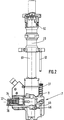
- the device comprises a rear handle 1 and a side handle 2, a combustion chamber 3, with its cover 4, its cover opening pusher 9, its wheel 10 and its adjustment slider 5 power, a trigger 6, a buffer guide 7, a buffer supply tube 8, a rod 11 of shuttle movement.
- the combustion chamber 3 is provided at the rear of the barrel 60, the front end of which is attached the buffer guide 7.
- the barrel 60 is slidably mounted in a barrel holder 61 intended to receive, before closing the cover 4 , a cartridge disc 62, one of which is intended to be covered by the barrel 60 in the firing and closing position of the combustion chamber 3.
- the gun holder 61, of axis 20, carries a finger 63 for controlling the movement of a buffer loading shuttle.
- the finger 63 extends, on the side of the gun holder, parallel to its axis 20.
- the device is a standing fire device.
- the sealing plugs are introduced into the tube 8.
- the rear of the barrel covers a cartridge and closes the chamber 3 and the finger 63 descends to actuate the rod 11.
- the firing is carried out by the trigger 6.
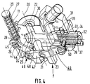
- the buffer guide 7 essentially comprises three bores.
- a third through bore 26 extends, on the side of the buffer guide, parallel to the central bore 21, 22. It receives the rod 11 of the shuttle movement. As the latter is itself displaced against the action of a compression spring 27, the bore 26 has an enlarged portion 28, for this spring 27, extending between the shoulder formed between the two portions of bore 26, 28 and head 29 of rod 11.
- the tampon guide Between the inner end 30 of the tampon guide, through which the central bore portion 22 of narrowed section extends, and the mouth of the transverse bore 23, the tampon guide has a tampon passage opening around which the end piece 31 of the supply tube 8 is fixed.
- the shuttle 34 shaped to slide in the bore 23, essentially comprises two juxtaposed and orthogonal sleeves between them.
- a first outer sleeve 32 which receives a displacement slide 33, and the bore 23 are coaxial.
- a second inner sleeve 35 has an axis parallel to the axis 20 of the device.
- the central bore of the sleeve 32 has an outer portion 36 of enlarged section to receive, between the shoulder formed between the two bore portions and the head 37 of the drawer 33, a compression damping spring 38.
- the central bore of the sleeve 35 has a section corresponding to that of the pads.
- the pads comprise a rod 39, with a head 40 and a pointed penetration end 41.
- a centering washer 42 of the same outside diameter as the head 40, is slid over the rod 39.
- the shuttle displacement rod 11 carries a lug 43 extending through a lumen 44 formed in one of the arms 45 of a connecting rod 46, with two V-shaped arms 45, 47, pivotally mounted around an axis 48 , driven into the buffer guide 7 and orthogonal to the axis 20 of the device and to the axis of the shuttle bore 23.
- the link 46 is articulated to another link 49 whose free end carries a lug displacement 50 extending through a lumen of the outer shuttle sleeve 32 and integral with the drawer 33.
- the barrel holder 61 slides on the barrel 60 in order, on the one hand, to control the closing of the combustion chamber 3, by covering the barrel with the barrel holder , and, on the other hand, control the movement of the shuttle 34 by sliding the finger 63 which causes the rod 11 to slide, which causes the connecting rod 46 to pivot, which, in turn, rotates the articulated end of it of the connecting rod 49 which slides the other end of the connecting rod 49 carrying the lug 50.
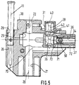
- the rod 11 brings down its lug 43 which is forced to slide in the lumen 44 of the arm 45 of the link 46, which forces the link 46 to pivot.
- the cooperation of the lug 43 with the edges of the light 44 and the relative displacement of the rods can lead to a widening of this light and play in the links which could limit the rotation of the link 46 and therefore the translation of the shuttle 34 if the invention had not been proposed.
- the spacing, at rest, between the finger 63 and the rod 11 is determined so that the abutment causes, in addition to the closing of the combustion chamber 3, the sliding of the rod 11 over a length which, taking into account the arrangement and dimensions of the rods 46, 49, the light 44 and the position of the lug 43 on the rod 11, should cause the shuttle 34 to slide beyond its abutment shoulder 25.
- the shuttle 34 comes into abutment on this shoulder, the continuation of the descent of the rod 11 continues to actuate the kinematic chain of the rods which, by the lug 50, causes the drawer 34 to slide in the drawer 33 against the action of the spring 38.
- the head 37 of the drawer 32 is then retracted inside the bore 36 of the shuttle (FIG. 6).
- the additional stroke of construction of the shuttle 34, made impossible by the stop 25, is therefore absorbed by the slide 33 and its spring 38. This additional stroke, or overtravel, therefore makes it possible to mitigate the wear of the parts of the kinematic chain of moving the shuttle 34.
- the latter comprises a lateral ramp 71 for raising the buffer.
- a ball 73 for retaining the bead, subjected to the action of a spring, not shown, for retaining the tampon until it is driven during firing.
Landscapes
- Engineering & Computer Science (AREA)
- Mechanical Engineering (AREA)
- Combustion & Propulsion (AREA)
- Chemical & Material Sciences (AREA)
- Physics & Mathematics (AREA)
- Fluid Mechanics (AREA)
- Portable Nailing Machines And Staplers (AREA)
- Piles And Underground Anchors (AREA)
- Details Of Spanners, Wrenches, And Screw Drivers And Accessories (AREA)
- Soil Working Implements (AREA)
- Toys (AREA)
- Nozzles (AREA)
- Absorbent Articles And Supports Therefor (AREA)
- Surgical Instruments (AREA)
- Eye Examination Apparatus (AREA)
- Control And Other Processes For Unpacking Of Materials (AREA)
Applications Claiming Priority (2)
| Application Number | Priority Date | Filing Date | Title |
|---|---|---|---|
| FR9404721 | 1994-04-20 | ||
| FR9404721A FR2718992B1 (fr) | 1994-04-20 | 1994-04-20 | Appareil de scellement de tampon. |
Publications (2)
| Publication Number | Publication Date |
|---|---|
| EP0678361A1 true EP0678361A1 (de) | 1995-10-25 |
| EP0678361B1 EP0678361B1 (de) | 1998-04-29 |
Family
ID=9462310
Family Applications (1)
| Application Number | Title | Priority Date | Filing Date |
|---|---|---|---|
| EP95400717A Expired - Lifetime EP0678361B1 (de) | 1994-04-20 | 1995-03-31 | Setzgerät für Befestigungsdübel |
Country Status (11)
| Country | Link |
|---|---|
| US (1) | US5692664A (de) |
| EP (1) | EP0678361B1 (de) |
| JP (1) | JPH0839455A (de) |
| KR (1) | KR0176988B1 (de) |
| CN (1) | CN1036509C (de) |
| AT (1) | ATE165544T1 (de) |
| CA (1) | CA2146810C (de) |
| DE (1) | DE69502232T2 (de) |
| FR (1) | FR2718992B1 (de) |
| NO (1) | NO305828B1 (de) |
| TW (1) | TW273526B (de) |
Families Citing this family (6)
| Publication number | Priority date | Publication date | Assignee | Title |
|---|---|---|---|---|
| US5897045A (en) * | 1997-09-12 | 1999-04-27 | Illinois Tool Works Inc. | Fastener dispensing apparatus for stand-up fastener driving tool and method therefor |
| US5918789A (en) * | 1997-09-12 | 1999-07-06 | Illinois Tool Works Inc. | Fastner collation tube for stand-up fastener driving tool |
| US6006976A (en) * | 1997-10-21 | 1999-12-28 | Robbins Manufacturing Co. | Wood tie end plating machine |
| US5927586A (en) * | 1997-10-21 | 1999-07-27 | Robbins Manufacturing Co. | Wood tie end plating machine |
| FR2846585B1 (fr) * | 2002-10-30 | 2006-02-03 | Prospection Et D Inv S Tech So | Tube d'alimentation en elements de fixation pour un appareil de fixation |
| USD560108S1 (en) | 2005-07-19 | 2008-01-22 | Milwaukee Electric Tool Corporation | Power tool, such as a nailer |
Citations (1)
| Publication number | Priority date | Publication date | Assignee | Title |
|---|---|---|---|---|
| EP0535826A1 (de) * | 1991-09-26 | 1993-04-07 | Illinois Tool Works Inc. | Eintreibgerät für Befestigungsmittel |
Family Cites Families (7)
| Publication number | Priority date | Publication date | Assignee | Title |
|---|---|---|---|---|
| US3760485A (en) * | 1972-05-19 | 1973-09-25 | F Smith | Threaded fastener feed drive and mechanism |
| US4765057A (en) * | 1980-02-02 | 1988-08-23 | Multifastener Corporation | Self-attaching fastener, panel assembly and installation apparatus |
| US4657167A (en) * | 1985-01-16 | 1987-04-14 | Mays Gary S | Automatic fastening machine for roof and deck coverings |
| US4699306A (en) * | 1985-12-10 | 1987-10-13 | Westinghouse Electric Corp. | Mechanical plug feeding mechanism |
| US4890968A (en) * | 1989-02-15 | 1990-01-02 | Illinois Tool Works Inc. | Stackable roofing washer |
| US5199506A (en) * | 1991-09-26 | 1993-04-06 | Illinois Tool Works Inc. | Fastener-driving tool assembly with improved fastener-loading features |
| US5199625A (en) * | 1991-09-26 | 1993-04-06 | Illinois Tool Works Inc. | Fastener-driving tool assembly with improved fastener-loading features |
-
1994
- 1994-04-20 FR FR9404721A patent/FR2718992B1/fr not_active Expired - Fee Related
-
1995
- 1995-03-31 AT AT95400717T patent/ATE165544T1/de not_active IP Right Cessation
- 1995-03-31 EP EP95400717A patent/EP0678361B1/de not_active Expired - Lifetime
- 1995-03-31 DE DE69502232T patent/DE69502232T2/de not_active Expired - Lifetime
- 1995-04-05 US US08/417,170 patent/US5692664A/en not_active Expired - Fee Related
- 1995-04-11 CA CA002146810A patent/CA2146810C/en not_active Expired - Fee Related
- 1995-04-18 TW TW084103771A patent/TW273526B/zh active
- 1995-04-19 NO NO951482A patent/NO305828B1/no unknown
- 1995-04-19 CN CN95105008A patent/CN1036509C/zh not_active Expired - Fee Related
- 1995-04-19 JP JP7093948A patent/JPH0839455A/ja active Pending
- 1995-04-20 KR KR1019950009291A patent/KR0176988B1/ko not_active Expired - Fee Related
Patent Citations (1)
| Publication number | Priority date | Publication date | Assignee | Title |
|---|---|---|---|---|
| EP0535826A1 (de) * | 1991-09-26 | 1993-04-07 | Illinois Tool Works Inc. | Eintreibgerät für Befestigungsmittel |
Also Published As
| Publication number | Publication date |
|---|---|
| FR2718992A1 (fr) | 1995-10-27 |
| US5692664A (en) | 1997-12-02 |
| NO305828B1 (no) | 1999-08-02 |
| KR950028868A (ko) | 1995-11-22 |
| CN1036509C (zh) | 1997-11-26 |
| EP0678361B1 (de) | 1998-04-29 |
| ATE165544T1 (de) | 1998-05-15 |
| DE69502232D1 (de) | 1998-06-04 |
| FR2718992B1 (fr) | 1996-06-28 |
| JPH0839455A (ja) | 1996-02-13 |
| CN1120991A (zh) | 1996-04-24 |
| CA2146810A1 (en) | 1995-10-21 |
| TW273526B (de) | 1996-04-01 |
| NO951482L (no) | 1995-10-23 |
| DE69502232T2 (de) | 1998-12-17 |
| CA2146810C (en) | 1999-06-29 |
| KR0176988B1 (ko) | 1999-04-01 |
| NO951482D0 (no) | 1995-04-19 |
Similar Documents
| Publication | Publication Date | Title |
|---|---|---|
| EP0727285B1 (de) | Setzgerät mit Kolben, angetrieben mit komprimiertem Gas | |
| FR2622826A1 (fr) | Outil a percussion | |
| FR2680234A1 (fr) | Dispositif de commande multifonction d'arme a feu. | |
| FR2608493A1 (fr) | Appareil de scellement a tir indirect | |
| EP0019537B1 (de) | Wegziehbarer Greifer | |
| EP0779132B1 (de) | Vorrichtung zum Festsetzen von Befestigungselementen | |
| FR2534173A1 (fr) | Appareil a enfoncer des clous et elements de fixation analogues | |
| EP0573093B1 (de) | Vorrichtung zum Bremsen des Rückstossschlittens einer Feuerwaffe | |
| EP0678361B1 (de) | Setzgerät für Befestigungsdübel | |
| FR2746690A1 (fr) | Appareil d'entrainement de tampon par masselotte a retour automatique en position du tir | |
| EP0567370A1 (de) | Vorrichtung zum Festsetzen Befestigungselementen mit einem Schlagbolzen, einem Sperrhakenmechanism und einem schwenkbaren Führung für das Element | |
| EP1445071B1 (de) | Nagelstreifen für Setzgerät mit Zuführeinrichtung für das Band, Gerät und Zuführeinrichtung | |
| EP0308321A1 (de) | Gerät zum Befestigen für Unterwasserarbeiten | |
| EP0868979A1 (de) | Eintreibgerät für Befestigungsmittel mit lösbare Laufhaltevorrichtung | |
| FR2523291A1 (fr) | Arme a air comprime | |
| EP0064644A1 (de) | Führungs- und Positioniermechanismus für die Bohrstange des Abstichloches am Schachtofen und Stichlochbohrmaschine mit einem solchen Mechanismus | |
| EP0314549B1 (de) | Patronenauswerfer für Einschlaggeräte | |
| EP1395379B1 (de) | Handwerkzeug zum setzen von befestigungselementen | |
| EP1067353B1 (de) | Abfeuerungsvorrichtung für Geschütz durch den Schlag eines Zünders | |
| EP0531595A1 (de) | Sicherheitsvorrichtung für automatische Feuerwaffen | |
| EP1291127A1 (de) | Zuführvorrichtung zum Zuführen von Stangen und Entfernen von Abfallstücken | |
| FR3087738A1 (fr) | Procede d'aide a la decompression de l'atmosphere d'un habitacle d'engin et habitacle d'engin apte a permettre la mise en œuvre dudit procede | |
| FR2765317A1 (fr) | Mecanisme d'armement desarmable pour fusil | |
| EP0138643A1 (de) | Betätigungsvorrichtung für Eisenbahnselbstentladewagentüren und damit ausgestattete Entlader | |
| FR2664685A1 (fr) | Dispositif de verrouillage de culasse pour arme automatique. |
Legal Events
| Date | Code | Title | Description |
|---|---|---|---|
| PUAI | Public reference made under article 153(3) epc to a published international application that has entered the european phase |
Free format text: ORIGINAL CODE: 0009012 |
|
| AK | Designated contracting states |
Kind code of ref document: A1 Designated state(s): AT BE CH DE ES FR GB IT LI NL SE |
|
| 17P | Request for examination filed |
Effective date: 19960403 |
|
| 17Q | First examination report despatched |
Effective date: 19961127 |
|
| GRAG | Despatch of communication of intention to grant |
Free format text: ORIGINAL CODE: EPIDOS AGRA |
|
| GRAG | Despatch of communication of intention to grant |
Free format text: ORIGINAL CODE: EPIDOS AGRA |
|
| GRAH | Despatch of communication of intention to grant a patent |
Free format text: ORIGINAL CODE: EPIDOS IGRA |
|
| GRAH | Despatch of communication of intention to grant a patent |
Free format text: ORIGINAL CODE: EPIDOS IGRA |
|
| GRAA | (expected) grant |
Free format text: ORIGINAL CODE: 0009210 |
|
| AK | Designated contracting states |
Kind code of ref document: B1 Designated state(s): AT BE CH DE ES FR GB IT LI NL SE |
|
| PG25 | Lapsed in a contracting state [announced via postgrant information from national office to epo] |
Ref country code: IT Free format text: LAPSE BECAUSE OF FAILURE TO SUBMIT A TRANSLATION OF THE DESCRIPTION OR TO PAY THE FEE WITHIN THE PRE;WARNING: LAPSES OF ITALIAN PATENTS WITH EFFECTIVE DATE BEFORE 2007 MAY HAVE OCCURRED AT ANY TIME BEFORE 2007. THE CORRECT EFFECTIVE DATE MAY BE DIFFERENT FROM THE ONE RECORDED.SCRIBED TIME-LIMIT Effective date: 19980429 Ref country code: GB Free format text: LAPSE BECAUSE OF FAILURE TO SUBMIT A TRANSLATION OF THE DESCRIPTION OR TO PAY THE FEE WITHIN THE PRESCRIBED TIME-LIMIT Effective date: 19980429 Ref country code: ES Free format text: THE PATENT HAS BEEN ANNULLED BY A DECISION OF A NATIONAL AUTHORITY Effective date: 19980429 Ref country code: AT Free format text: LAPSE BECAUSE OF FAILURE TO SUBMIT A TRANSLATION OF THE DESCRIPTION OR TO PAY THE FEE WITHIN THE PRESCRIBED TIME-LIMIT Effective date: 19980429 |
|
| REF | Corresponds to: |
Ref document number: 165544 Country of ref document: AT Date of ref document: 19980515 Kind code of ref document: T |
|
| REG | Reference to a national code |
Ref country code: CH Ref legal event code: EP |
|
| REF | Corresponds to: |
Ref document number: 69502232 Country of ref document: DE Date of ref document: 19980604 |
|
| GBV | Gb: ep patent (uk) treated as always having been void in accordance with gb section 77(7)/1977 [no translation filed] |
Effective date: 19980429 |
|
| PLBE | No opposition filed within time limit |
Free format text: ORIGINAL CODE: 0009261 |
|
| STAA | Information on the status of an ep patent application or granted ep patent |
Free format text: STATUS: NO OPPOSITION FILED WITHIN TIME LIMIT |
|
| PG25 | Lapsed in a contracting state [announced via postgrant information from national office to epo] |
Ref country code: LI Free format text: LAPSE BECAUSE OF NON-PAYMENT OF DUE FEES Effective date: 19990331 Ref country code: CH Free format text: LAPSE BECAUSE OF NON-PAYMENT OF DUE FEES Effective date: 19990331 Ref country code: BE Free format text: LAPSE BECAUSE OF NON-PAYMENT OF DUE FEES Effective date: 19990331 |
|
| 26N | No opposition filed | ||
| BERE | Be: lapsed |
Owner name: SOC. DE PROSPECTION ET D'INVENTIONS TECHNIQUES SP Effective date: 19990331 |
|
| REG | Reference to a national code |
Ref country code: CH Ref legal event code: PL |
|
| PGFP | Annual fee paid to national office [announced via postgrant information from national office to epo] |
Ref country code: SE Payment date: 20090327 Year of fee payment: 15 |
|
| EUG | Se: european patent has lapsed | ||
| PG25 | Lapsed in a contracting state [announced via postgrant information from national office to epo] |
Ref country code: SE Free format text: LAPSE BECAUSE OF NON-PAYMENT OF DUE FEES Effective date: 20100401 |
|
| PGFP | Annual fee paid to national office [announced via postgrant information from national office to epo] |
Ref country code: DE Payment date: 20130327 Year of fee payment: 19 Ref country code: FR Payment date: 20130405 Year of fee payment: 19 |
|
| PGFP | Annual fee paid to national office [announced via postgrant information from national office to epo] |
Ref country code: NL Payment date: 20130326 Year of fee payment: 19 |
|
| REG | Reference to a national code |
Ref country code: DE Ref legal event code: R119 Ref document number: 69502232 Country of ref document: DE |
|
| REG | Reference to a national code |
Ref country code: NL Ref legal event code: V1 Effective date: 20141001 |
|
| REG | Reference to a national code |
Ref country code: FR Ref legal event code: ST Effective date: 20141128 |
|
| REG | Reference to a national code |
Ref country code: DE Ref legal event code: R119 Ref document number: 69502232 Country of ref document: DE Effective date: 20141001 |
|
| PG25 | Lapsed in a contracting state [announced via postgrant information from national office to epo] |
Ref country code: DE Free format text: LAPSE BECAUSE OF NON-PAYMENT OF DUE FEES Effective date: 20141001 Ref country code: FR Free format text: LAPSE BECAUSE OF NON-PAYMENT OF DUE FEES Effective date: 20140331 |
|
| PG25 | Lapsed in a contracting state [announced via postgrant information from national office to epo] |
Ref country code: NL Free format text: LAPSE BECAUSE OF NON-PAYMENT OF DUE FEES Effective date: 20141001 |