EP0678414B1 - Véhicule hybride - Google Patents
Véhicule hybride Download PDFInfo
- Publication number
- EP0678414B1 EP0678414B1 EP95105340A EP95105340A EP0678414B1 EP 0678414 B1 EP0678414 B1 EP 0678414B1 EP 95105340 A EP95105340 A EP 95105340A EP 95105340 A EP95105340 A EP 95105340A EP 0678414 B1 EP0678414 B1 EP 0678414B1
- Authority
- EP
- European Patent Office
- Prior art keywords
- signal
- power
- value
- desired power
- speed
- Prior art date
- Legal status (The legal status is an assumption and is not a legal conclusion. Google has not performed a legal analysis and makes no representation as to the accuracy of the status listed.)
- Expired - Lifetime
Links
Images


Classifications
-
- B—PERFORMING OPERATIONS; TRANSPORTING
- B60—VEHICLES IN GENERAL
- B60K—ARRANGEMENT OR MOUNTING OF PROPULSION UNITS OR OF TRANSMISSIONS IN VEHICLES; ARRANGEMENT OR MOUNTING OF PLURAL DIVERSE PRIME-MOVERS IN VEHICLES; AUXILIARY DRIVES FOR VEHICLES; INSTRUMENTATION OR DASHBOARDS FOR VEHICLES; ARRANGEMENTS IN CONNECTION WITH COOLING, AIR INTAKE, GAS EXHAUST OR FUEL SUPPLY OF PROPULSION UNITS IN VEHICLES
- B60K6/00—Arrangement or mounting of plural diverse prime-movers for mutual or common propulsion, e.g. hybrid propulsion systems comprising electric motors and internal combustion engines
- B60K6/20—Arrangement or mounting of plural diverse prime-movers for mutual or common propulsion, e.g. hybrid propulsion systems comprising electric motors and internal combustion engines the prime-movers consisting of electric motors and internal combustion engines, e.g. HEVs
- B60K6/42—Arrangement or mounting of plural diverse prime-movers for mutual or common propulsion, e.g. hybrid propulsion systems comprising electric motors and internal combustion engines the prime-movers consisting of electric motors and internal combustion engines, e.g. HEVs characterised by the architecture of the hybrid electric vehicle
- B60K6/46—Series type
-
- B—PERFORMING OPERATIONS; TRANSPORTING
- B60—VEHICLES IN GENERAL
- B60W—CONJOINT CONTROL OF VEHICLE SUB-UNITS OF DIFFERENT TYPE OR DIFFERENT FUNCTION; CONTROL SYSTEMS SPECIALLY ADAPTED FOR HYBRID VEHICLES; ROAD VEHICLE DRIVE CONTROL SYSTEMS FOR PURPOSES NOT RELATED TO THE CONTROL OF A PARTICULAR SUB-UNIT
- B60W20/00—Control systems specially adapted for hybrid vehicles
- B60W20/10—Controlling the power contribution of each of the prime movers to meet required power demand
-
- B—PERFORMING OPERATIONS; TRANSPORTING
- B60—VEHICLES IN GENERAL
- B60L—PROPULSION OF ELECTRICALLY-PROPELLED VEHICLES; SUPPLYING ELECTRIC POWER FOR AUXILIARY EQUIPMENT OF ELECTRICALLY-PROPELLED VEHICLES; ELECTRODYNAMIC BRAKE SYSTEMS FOR VEHICLES IN GENERAL; MAGNETIC SUSPENSION OR LEVITATION FOR VEHICLES; MONITORING OPERATING VARIABLES OF ELECTRICALLY-PROPELLED VEHICLES; ELECTRIC SAFETY DEVICES FOR ELECTRICALLY-PROPELLED VEHICLES
- B60L15/00—Methods, circuits, or devices for controlling the traction-motor speed of electrically-propelled vehicles
- B60L15/20—Methods, circuits, or devices for controlling the traction-motor speed of electrically-propelled vehicles for control of the vehicle or its driving motor to achieve a desired performance, e.g. speed, torque, programmed variation of speed
-
- B—PERFORMING OPERATIONS; TRANSPORTING
- B60—VEHICLES IN GENERAL
- B60L—PROPULSION OF ELECTRICALLY-PROPELLED VEHICLES; SUPPLYING ELECTRIC POWER FOR AUXILIARY EQUIPMENT OF ELECTRICALLY-PROPELLED VEHICLES; ELECTRODYNAMIC BRAKE SYSTEMS FOR VEHICLES IN GENERAL; MAGNETIC SUSPENSION OR LEVITATION FOR VEHICLES; MONITORING OPERATING VARIABLES OF ELECTRICALLY-PROPELLED VEHICLES; ELECTRIC SAFETY DEVICES FOR ELECTRICALLY-PROPELLED VEHICLES
- B60L50/00—Electric propulsion with power supplied within the vehicle
- B60L50/10—Electric propulsion with power supplied within the vehicle using propulsion power supplied by engine-driven generators, e.g. generators driven by combustion engines
- B60L50/15—Electric propulsion with power supplied within the vehicle using propulsion power supplied by engine-driven generators, e.g. generators driven by combustion engines with additional electric power supply
-
- B—PERFORMING OPERATIONS; TRANSPORTING
- B60—VEHICLES IN GENERAL
- B60L—PROPULSION OF ELECTRICALLY-PROPELLED VEHICLES; SUPPLYING ELECTRIC POWER FOR AUXILIARY EQUIPMENT OF ELECTRICALLY-PROPELLED VEHICLES; ELECTRODYNAMIC BRAKE SYSTEMS FOR VEHICLES IN GENERAL; MAGNETIC SUSPENSION OR LEVITATION FOR VEHICLES; MONITORING OPERATING VARIABLES OF ELECTRICALLY-PROPELLED VEHICLES; ELECTRIC SAFETY DEVICES FOR ELECTRICALLY-PROPELLED VEHICLES
- B60L50/00—Electric propulsion with power supplied within the vehicle
- B60L50/10—Electric propulsion with power supplied within the vehicle using propulsion power supplied by engine-driven generators, e.g. generators driven by combustion engines
- B60L50/16—Electric propulsion with power supplied within the vehicle using propulsion power supplied by engine-driven generators, e.g. generators driven by combustion engines with provision for separate direct mechanical propulsion
-
- B—PERFORMING OPERATIONS; TRANSPORTING
- B60—VEHICLES IN GENERAL
- B60W—CONJOINT CONTROL OF VEHICLE SUB-UNITS OF DIFFERENT TYPE OR DIFFERENT FUNCTION; CONTROL SYSTEMS SPECIALLY ADAPTED FOR HYBRID VEHICLES; ROAD VEHICLE DRIVE CONTROL SYSTEMS FOR PURPOSES NOT RELATED TO THE CONTROL OF A PARTICULAR SUB-UNIT
- B60W10/00—Conjoint control of vehicle sub-units of different type or different function
- B60W10/04—Conjoint control of vehicle sub-units of different type or different function including control of propulsion units
- B60W10/06—Conjoint control of vehicle sub-units of different type or different function including control of propulsion units including control of combustion engines
-
- B—PERFORMING OPERATIONS; TRANSPORTING
- B60—VEHICLES IN GENERAL
- B60W—CONJOINT CONTROL OF VEHICLE SUB-UNITS OF DIFFERENT TYPE OR DIFFERENT FUNCTION; CONTROL SYSTEMS SPECIALLY ADAPTED FOR HYBRID VEHICLES; ROAD VEHICLE DRIVE CONTROL SYSTEMS FOR PURPOSES NOT RELATED TO THE CONTROL OF A PARTICULAR SUB-UNIT
- B60W10/00—Conjoint control of vehicle sub-units of different type or different function
- B60W10/04—Conjoint control of vehicle sub-units of different type or different function including control of propulsion units
- B60W10/08—Conjoint control of vehicle sub-units of different type or different function including control of propulsion units including control of electric propulsion units, e.g. motors or generators
-
- B—PERFORMING OPERATIONS; TRANSPORTING
- B60—VEHICLES IN GENERAL
- B60W—CONJOINT CONTROL OF VEHICLE SUB-UNITS OF DIFFERENT TYPE OR DIFFERENT FUNCTION; CONTROL SYSTEMS SPECIALLY ADAPTED FOR HYBRID VEHICLES; ROAD VEHICLE DRIVE CONTROL SYSTEMS FOR PURPOSES NOT RELATED TO THE CONTROL OF A PARTICULAR SUB-UNIT
- B60W20/00—Control systems specially adapted for hybrid vehicles
-
- B—PERFORMING OPERATIONS; TRANSPORTING
- B60—VEHICLES IN GENERAL
- B60L—PROPULSION OF ELECTRICALLY-PROPELLED VEHICLES; SUPPLYING ELECTRIC POWER FOR AUXILIARY EQUIPMENT OF ELECTRICALLY-PROPELLED VEHICLES; ELECTRODYNAMIC BRAKE SYSTEMS FOR VEHICLES IN GENERAL; MAGNETIC SUSPENSION OR LEVITATION FOR VEHICLES; MONITORING OPERATING VARIABLES OF ELECTRICALLY-PROPELLED VEHICLES; ELECTRIC SAFETY DEVICES FOR ELECTRICALLY-PROPELLED VEHICLES
- B60L2240/00—Control parameters of input or output; Target parameters
- B60L2240/10—Vehicle control parameters
- B60L2240/12—Speed
-
- B—PERFORMING OPERATIONS; TRANSPORTING
- B60—VEHICLES IN GENERAL
- B60L—PROPULSION OF ELECTRICALLY-PROPELLED VEHICLES; SUPPLYING ELECTRIC POWER FOR AUXILIARY EQUIPMENT OF ELECTRICALLY-PROPELLED VEHICLES; ELECTRODYNAMIC BRAKE SYSTEMS FOR VEHICLES IN GENERAL; MAGNETIC SUSPENSION OR LEVITATION FOR VEHICLES; MONITORING OPERATING VARIABLES OF ELECTRICALLY-PROPELLED VEHICLES; ELECTRIC SAFETY DEVICES FOR ELECTRICALLY-PROPELLED VEHICLES
- B60L2240/00—Control parameters of input or output; Target parameters
- B60L2240/40—Drive Train control parameters
- B60L2240/42—Drive Train control parameters related to electric machines
- B60L2240/421—Speed
-
- B—PERFORMING OPERATIONS; TRANSPORTING
- B60—VEHICLES IN GENERAL
- B60L—PROPULSION OF ELECTRICALLY-PROPELLED VEHICLES; SUPPLYING ELECTRIC POWER FOR AUXILIARY EQUIPMENT OF ELECTRICALLY-PROPELLED VEHICLES; ELECTRODYNAMIC BRAKE SYSTEMS FOR VEHICLES IN GENERAL; MAGNETIC SUSPENSION OR LEVITATION FOR VEHICLES; MONITORING OPERATING VARIABLES OF ELECTRICALLY-PROPELLED VEHICLES; ELECTRIC SAFETY DEVICES FOR ELECTRICALLY-PROPELLED VEHICLES
- B60L2240/00—Control parameters of input or output; Target parameters
- B60L2240/40—Drive Train control parameters
- B60L2240/44—Drive Train control parameters related to combustion engines
- B60L2240/441—Speed
-
- B—PERFORMING OPERATIONS; TRANSPORTING
- B60—VEHICLES IN GENERAL
- B60L—PROPULSION OF ELECTRICALLY-PROPELLED VEHICLES; SUPPLYING ELECTRIC POWER FOR AUXILIARY EQUIPMENT OF ELECTRICALLY-PROPELLED VEHICLES; ELECTRODYNAMIC BRAKE SYSTEMS FOR VEHICLES IN GENERAL; MAGNETIC SUSPENSION OR LEVITATION FOR VEHICLES; MONITORING OPERATING VARIABLES OF ELECTRICALLY-PROPELLED VEHICLES; ELECTRIC SAFETY DEVICES FOR ELECTRICALLY-PROPELLED VEHICLES
- B60L2240/00—Control parameters of input or output; Target parameters
- B60L2240/80—Time limits
-
- Y—GENERAL TAGGING OF NEW TECHNOLOGICAL DEVELOPMENTS; GENERAL TAGGING OF CROSS-SECTIONAL TECHNOLOGIES SPANNING OVER SEVERAL SECTIONS OF THE IPC; TECHNICAL SUBJECTS COVERED BY FORMER USPC CROSS-REFERENCE ART COLLECTIONS [XRACs] AND DIGESTS
- Y02—TECHNOLOGIES OR APPLICATIONS FOR MITIGATION OR ADAPTATION AGAINST CLIMATE CHANGE
- Y02T—CLIMATE CHANGE MITIGATION TECHNOLOGIES RELATED TO TRANSPORTATION
- Y02T10/00—Road transport of goods or passengers
- Y02T10/60—Other road transportation technologies with climate change mitigation effect
- Y02T10/62—Hybrid vehicles
-
- Y—GENERAL TAGGING OF NEW TECHNOLOGICAL DEVELOPMENTS; GENERAL TAGGING OF CROSS-SECTIONAL TECHNOLOGIES SPANNING OVER SEVERAL SECTIONS OF THE IPC; TECHNICAL SUBJECTS COVERED BY FORMER USPC CROSS-REFERENCE ART COLLECTIONS [XRACs] AND DIGESTS
- Y02—TECHNOLOGIES OR APPLICATIONS FOR MITIGATION OR ADAPTATION AGAINST CLIMATE CHANGE
- Y02T—CLIMATE CHANGE MITIGATION TECHNOLOGIES RELATED TO TRANSPORTATION
- Y02T10/00—Road transport of goods or passengers
- Y02T10/60—Other road transportation technologies with climate change mitigation effect
- Y02T10/64—Electric machine technologies in electromobility
-
- Y—GENERAL TAGGING OF NEW TECHNOLOGICAL DEVELOPMENTS; GENERAL TAGGING OF CROSS-SECTIONAL TECHNOLOGIES SPANNING OVER SEVERAL SECTIONS OF THE IPC; TECHNICAL SUBJECTS COVERED BY FORMER USPC CROSS-REFERENCE ART COLLECTIONS [XRACs] AND DIGESTS
- Y02—TECHNOLOGIES OR APPLICATIONS FOR MITIGATION OR ADAPTATION AGAINST CLIMATE CHANGE
- Y02T—CLIMATE CHANGE MITIGATION TECHNOLOGIES RELATED TO TRANSPORTATION
- Y02T10/00—Road transport of goods or passengers
- Y02T10/60—Other road transportation technologies with climate change mitigation effect
- Y02T10/7072—Electromobility specific charging systems or methods for batteries, ultracapacitors, supercapacitors or double-layer capacitors
-
- Y—GENERAL TAGGING OF NEW TECHNOLOGICAL DEVELOPMENTS; GENERAL TAGGING OF CROSS-SECTIONAL TECHNOLOGIES SPANNING OVER SEVERAL SECTIONS OF THE IPC; TECHNICAL SUBJECTS COVERED BY FORMER USPC CROSS-REFERENCE ART COLLECTIONS [XRACs] AND DIGESTS
- Y02—TECHNOLOGIES OR APPLICATIONS FOR MITIGATION OR ADAPTATION AGAINST CLIMATE CHANGE
- Y02T—CLIMATE CHANGE MITIGATION TECHNOLOGIES RELATED TO TRANSPORTATION
- Y02T10/00—Road transport of goods or passengers
- Y02T10/60—Other road transportation technologies with climate change mitigation effect
- Y02T10/72—Electric energy management in electromobility
Definitions
- a vehicle having the above characteristics which is often referred to as a hybrid vehicle, is described in PCT patent application published under number W0 93/07022.
- This characteristic gives this vehicle the advantage that it must not include a storage battery great capacity such as that which in others known vehicles of the same kind, provides at least partially and / or temporarily electrical energy consumed by the traction motor.
- the vehicle described in the patent application W0 93/07022 mentioned above has a circuit control which controls the electrical power supplied to the traction motor with variable setpoint power determined by the position of an accelerator pedal.
- the circuit setting determines a new setpoint power corresponding to the new pedal position accelerator and a new rotation speed of setpoint which is the one at which the combustion engine internal vehicle must rotate to provide mechanical power equal, except for losses, to power above mentioned deposit while consuming only the lowest possible amount of fuel.
- control circuit does not not modify the electrical power supplied by the generator to the traction motor, but only acts on the internal combustion engine so that the power mechanics provided by the latter increases. That power mechanical now being greater than the power electric supplied by the generator, the speed of rotation of the internal combustion engine increases.
- a known vehicle such as that described above still has the disadvantage that when its driver quickly moves his accelerator pedal a quantity important while stopped or driving low speed, the control circuit provides the motor with traction all-electric power corresponding to the new position of the accelerator pedal as soon as the internal combustion engine reached new speed deposit, as described above.
- the traction motor is still stopped, or turns only slowly.
- the current it absorbs can so be very high and have intensity several times greater than that of the current absorbed by this motor traction when it turns at its maximum speed in providing its maximum mechanical power.
- An object of the present invention is to provide a vehicle of the same kind as that described above but which does not have the disadvantages of this one, that is to say a vehicle in which the electric power supplied to the traction motor increases immediately when the driver presses its accelerator pedal and in which the current absorbed by the traction motor never exceeds the value that it has when this traction motor turns at its speed maximum by providing its maximum power.
- a vehicle according to the present invention reacts exactly like a conventional vehicle when the driver presses the pedal accelerator, the electrical power supplied to the engine of traction increasing with the power mechanical provided by the internal combustion engine, without that it is necessary to wait for this engine to internal combustion has reached its new speed of rotation as in the known vehicle described in the Patent application WO 93/07022.
- these electronic components can be cheaper, all other things being equal, than the corresponding electronic components of the vehicle known mentioned above and that the cost price of vehicle according to the present invention can therefore be more low, all other things being as equal, as that of this known vehicle.
- the vehicle according to the present invention is designated by the general reference 1.
- Vehicle 1 has an internal combustion engine 2 including the fuel supply member and oxidizer is designated by reference 2a.
- the motor 2 is, in the present example, a motor with classic explosion and that its feeder 2a is constituted by an equally conventional carburetor.
- the engine 2 can be of any of the various types of well known internal combustion engines such as, for for example, diesel engines or gas turbines.
- the organ 2a can be of any one of the various types of feeders adapted respectively to these various types of internal combustion engines.
- the engine 2 is an internal combustion engine as in this example, its feed member 2a can of course be constituted by a system with injection also well known.
- the carburetor 2a of the internal combustion engine 2 is arranged so that its butterfly, not shown separately, passes from its fully closed position to its position fully open when this SP control signal varies from a minimum value SPmin to a maximum value SPmax.
- the signal SP therefore constitutes a control signal for the mechanical power P supplied by the motor 2, this power P obviously being equal to its maximum value Pmax when the signal SP has its maximum value SPmax.
- the curve C2a in FIG. 2 represents schematically the well-known variation of this maximum power Pmax as a function of the speed of motor V rotation 2.
- this fraction f must be less than 100%. But the man of the trade will understand that this fraction f must not be too small, because then motor 2 would run the most of the time with a yield significantly lower than its maximum yield. In practice we will choose to preference for this fraction f a value between 90% and 70%, for example a value of around 80%.
- the curve C2b also plotted in Figure 2 schematically represents the variation of this power mechanical Pf as a function of the speed of rotation V of the motor 2 in the case where the fraction f mentioned above is equal to 80%.
- the power mechanical P provided by motor 2 is zero, or at least practically zero, when the signal SP has its value minimum SPmin, the curve representing this power mechanical P then practically merging with the axis on the abscissa of figure 2.
- the mechanical power P supplied by the motor 2 is also zero, or practically zero, when the speed of rotation V of this motor 2 is equal to or less than its speed generally called idling speed and designated by the reference Vr in FIG. 2.
- the output shaft of motor 2 is connected to the rotor, not shown separately, of a rotary energy generator electrical 3 by a mechanical connection symbolized in the Figure 1 with a double line.
- the electrical power supplied by the generator 3 in response to the mechanical power P it receives from engine 2 will be designated by the reference E.
- the difference between this mechanical power P and this power electric F, which represents the power dissipated in the generator 3, will be designated by the reference DG.
- engine 2 and generator 3 are separate from each other, but it's obvious that they can also be joined together.
- the mechanical connection between the output shaft of motor 2 and the rotor of generator 3 can be direct, as it has been represented, or be carried out through a gear train or other similar device.
- Vehicle 1 includes a measuring device 4 providing an SMV measurement signal proportional to the rotation speed V of the internal combustion engine 2, which is obviously also, in this example, the speed of rotation of generator 3.
- FIG. 2 therefore represents also the variation of the mechanical powers Pmax and Pf as a function of the value of the SMV signal.
- the measuring device 4 comprises a fixed disc 4a concentrically with the shaft connecting motor 2 to generator 3 and an electronic circuit 4b associated with a photoelectric or magnetic sensor, not shown separately and producing the SMV signal in response to the passage in front of this tooth or hole sensor arranged regularly at the periphery of the disc 4a and which have also not been shown separately.
- the measuring device 4 will not be described further in detail because it is a well known device that can incidentally be achieved in various other ways also well known.
- Vehicle 1 further includes an electric motor 5 whose rotor, not shown separately, is connected to a driving wheel 6 also by a mechanical connection symbolized by a double line.
- the motor 5 and the wheel 6 are also separated in the Figure 1, but it is obvious that they can also to be joined to each other. Likewise, the mechanical connection between the rotor of the motor 5 and the wheel 6 can be direct, as shown, or be performed by through a gear train or any other similar device.
- Motor 5 which is the traction motor of the vehicle 1, will not be described in detail since it may be of any of the various types of electric motors which are suitable for this purpose and which are well known.
- the motor 5 is an asynchronous motor.
- the vehicle 1 includes yet another device for measurement, designated by reference 7, providing a signal SMW measuring device proportional to the rotation speed W of the motor 5 which is obviously also in the present example, the speed of rotation of the wheel 6.
- the measuring device 7 comprises a disc 7a similar to disc 4a mentioned above and fixed concentrically with the shaft connecting the motor 5 to the wheel 6, as well as an electronic circuit 7b similar to circuit 4b also mentioned above and providing the SMW signal.
- the measuring device 7 will also not be described in detail for the same reasons as those which have been mentioned above with regard to the measuring device 4.
- the vehicle 1 also includes a device for control 8 on which the driver of this vehicle 1 can act to regulate the speed of the latter.
- control device 8 has an accelerator pedal 8a coupled mechanically to a sensor 8b providing an SCF signal representative of the position of this pedal 8a.
- the pedal 8a accelerator can be replaced by any other suitable control device, for example by a lever manually operable by the driver of the vehicle. Such an execution was not represented.
- the sensor 8b will not be described in detail because it it is a device that can be realized in various ways well known to specialists.
- each position of the accelerator pedal 8a corresponds to a power of instruction, which will be called FC in the rest of this description, and whose value, which is proportional to the value of the SCF signal, is that the power supplied to motor 5 by its circuit command, which will be described later, should have that the speed of vehicle 1 remains at the speed desired by the driver of this vehicle 1 or reaches this last speed.
- the electric power supplied to the motor 5 by its control circuit will be designated by the reference F in the rest of this description.
- the SCF signal and the FC reference power have obviously a zero value when the driver of the vehicle 1 does not touch the accelerator pedal 8a, and a maximum value SCFmax and, respectively, FCmax when this driver presses this pedal 8a against his end stop.
- the proportionality ratio between the SCF signal and the setpoint power FC will be designated by R in the following this description.
- the vehicle 1 also includes an adjustment circuit 9 which is particularly intended to enslave the power electric F supplied to motor 5 at the power of HR setpoint determined by pedal position accelerator 8a.
- the adjustment circuit 9 is also intended for set the rotation speed V of the internal combustion engine 2 to the value for which the latter provides, when the control signal SP of its carburetor 2a has the value SPf defined above, a mechanical power P equal to the sum of the electric power F supplied to the motor 5, DG losses in generator 3 and losses in the control circuit for this motor 5. These latest losses will be designated by DC in the rest of this description.
- the adjustment circuit 9 includes in particular a control circuit 10 arranged between generator 3 and engine 5.
- the control circuit 10 comprises, so conventional, a control circuit 10a of the motor 5, a measuring circuit 10b of the electrical power F supplied by this control circuit 10a to the motor 5, and a circuit integrator 10c.
- the control circuit 10a receives from generator 3 the electric power E supplied by the latter, and it is arranged to supply motor 5 with voltage and / or a current having a shape adapted to the nature of this motor 5, and to adjust the electric power F supplied to the latter as a function of a control signal SF of which the elaboration will be described later.
- the control circuit 10a can be by example arranged so as to apply to this motor 5 a alternating voltage formed of pulses having a fixed amplitude but a frequency and a duty cycle variables depending on the SF signal.
- This technique of production of this voltage is often referred to as PWM initials of its name in English (Pulse Width Modulation).
- the measurement circuit 10b is arranged so as to provide an SMF measurement signal proportional to the electrical power F supplied by the control circuit 10a to motor 5.
- the integrator circuit 10c is arranged so as to produce the SF signal with a value equal to the integral as a function of time the difference between a signal of setpoint SCFa and the measurement signal SMF mentioned above.
- the creation of the SCFa setpoint signal will be described later. We will simply mention here that this SCFa signal is proportional to a set power FCa which we will also see later that it can take various values, the proportionality ratio between the signal SCFa and the setpoint power FCa also having the R-value mentioned above.
- the three circuits 10a, 10b and 10c will not be described in more detail because they can be made from various ways well known to specialists.
- the control signal SF has a value such as the electric power F supplied to the motor 5 is equal to the set power FCa. If the signal SCFa increases, for example, the difference between this SCFa signal and the SMF signal becomes positive, and the signal SF, which is equal to the integral as a function of time of this difference, increases, so that the power electric F also increases, as does the SMF signal. When the latter becomes equal to the signal SCFa, the difference between these two signals is canceled and the signal SF stops increasing. A similar process takes place obviously when the difference between the SCFa signals and SMF becomes negative.
- the power dissipated in the measurement circuit 10b of the electric power F is zero or at least negligible compared to this last.
- the components of the control circuit 10a which are traversed by the current supplied to the motor 5 are dimensioned so that their nominal current, that is to say the current maximum they can endure permanently without damage, equal to the current absorbed by this motor 5 when it is running at its maximum speed providing its maximum mechanical power.
- This current absorbed by the motor 5 in these conditions is obviously significantly lower than that that this motor 5 can absorb when it runs at low speed or that it is stopped.
- the curve C3 in Figure 3 represents schematically the variation of this electrical power maximum FM as a function of the rotation speed W of the motor 5, which is a characteristic of the assembly formed by the control circuit 10a and by this motor 5.
- This figure 3 shows that the electrical power maximum FM that the control circuit 10a can supply without damage to the motor 5 varies from a minimum value FMmin at a maximum value FMmax when the speed of rotation W of motor 5 varies from zero to a WA value and remains equal at this maximum value FMmax when this speed of rotation W increases beyond this value WA.
- the SCF setpoint signal produced by the sensor 8b has its maximum value SCFmax which is proportional to the maximum value FCmax of the power de-set FC.
- the value of this power of setpoint FC is that the electrical power F supplied by the control circuit 10a must have in order for vehicle 1 travels at the desired speed or reaches the latter. It is therefore obvious that the circuit of command 10a must be dimensioned so that the FMmax value of the maximum FM power it can supply without damage to motor 5 is at least equal to the FCmax value of the FC setpoint power. We will admit in the rest of this description that the circuit of command 10a is dimensioned so that these values FMmax and FCmax are equal.
- the adjustment circuit 9 also includes a first signal processing circuit, designated by the reference 11, the input of which is connected to the electronic circuit 7b of the device 7 for measuring the speed of rotation W of the traction motor 5 and therefore receives the measurement signal SMW proportional to this speed of rotation W.
- the signal processing circuit 11 is arranged so as to produce a limitation signal SL proportional to the maximum electrical power FM defined above.
- the signal SL therefore also passes from a value SLmin, corresponding to FMmin, to a SLmax value, corresponding to FMmax, when the value of the SMW signal goes from zero to the SMWA value corresponding to the rotation speed WA, and stays at this SLmax value when the SMW signal increases beyond SMWA.
- the curve C3 in Figure 3 therefore also represents the variation of the SL signal as a function of the SMW signal when the scales of the two axes of the diagram of this Figure 3 are chosen accordingly.
- circuit treatment 11 can advantageously consist of a read only memory, which is a well known component and does not will therefore not be described in detail.
- the processing circuit 11 is arranged so that the proportionality between the signal SL and the FM power also has the R value mentioned above.
- the adjustment circuit 9 also includes a circuit multiplier 12 having two inputs which receive respectively the signal SCF and the signal SL.
- the multiplier circuit 12 is arranged so that the value of the signal SCFb which it provides at its output is always equal to the product of the value of the SCF signal and the relationship between the value of the signal SL and its value maximum SLmax.
- the SCFb signal is a signal power setpoint proportional to a power of FCb setpoint, the proportionality ratio between this signal SCFb and this setpoint power FCb also having the R value defined above.
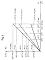
- the lines designated by C4a and C4b in Figure 4 represent respectively, by way of example, the variation of the SCFb signal as a function of the SCF signal and therefore the variation of the set power FCb as a function of the setpoint power FC for the two values SLmax and SLmin of the SL signal.
- the multiplier circuit 12 will not be described further in detail because it can be done in various ways well known to those skilled in the art.
- the adjustment circuit 9 comprises a second circuit signal processing, designated by reference 13, which responds to the power setpoint signal SCFb for produce an SCV signal which we will see is a signal speed setpoint proportional to a speed of setpoint rotation of the internal combustion engine 2.
- the processing circuit 13 is arranged so that for each value of the SCFb signal, and therefore for each value of the set power FCb, the signal SCV has a value equal to that which the SMV signal has when the signal SP for controlling the carburetor 2a of the engine 2 a its SPf value defined above and that motor 2 is running at speed V for which the mechanical power P that it produces is equal to the sum of the power of FCb setpoint and DG and DC powers dissipated in the generator 3 and in the control circuit 10a.
- the setpoint speed VC proportional to the SCV setpoint signal is that at which the engine 2 should rotate, when the throttle its carburetor 2a is in the position corresponding to the SPf value of the SP signal, to provide power mechanical P equal to the sum of the setpoint power FCb proportional to the SCFb signal and powers dissipated DG and DC defined above.
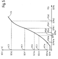
- Curve C5 in Figure 5 represents the characteristic of the processing circuit 13, i.e. the variation of the SCV signal as a function of the SCFb signal and therefore, if the scales of the two axes of this figure 5 are chosen appropriately, the variation in the speed of setpoint VC as a function of the setpoint power FCb.
- circuit treatment 13 can also be advantageously constituted by a read only memory.
- the signal SCV produced by the processing circuit 13 is applied to a first input of a circuit comparator 14 which has a second input to which is applied the SMV signal proportional to the speed of motor V rotation 2.
- Comparator 14 has an output which produces the signal Carburetor control SP 2a of engine 2, and it is arranged so that this signal SP selectively takes its SPmax, SPF and SPmin values depending on whether the SCV signal is respectively greater than, equal to or less than the signal SMV.
- the comparator 14 and the carburetor 2a together constitute a circuit for controlling the speed of rotation V of the motor 2 at the setpoint speed VC proportional to the SCV signal.
- this comparator 14, this carburetor 2a and the processing circuit 13 together constitute a mechanical power control circuit P supplied by motor 2 at the sum of the power of FCb setpoint proportional to the SCFb signal and dissipated powers DG and DC defined above.
- the SMV signal proportional to the speed of rotation Motor 2 V is also applied to the input of a third signal processing circuit which is designated by reference 15.
- the signal processing circuit 15 is arranged to so that, for each value of the SMV signal, the signal SCFc that it produces at its exit is proportional to a setpoint power FCc equal to the difference between, on the one hand, the mechanical power P supplied by the motor 2 when it rotates at the speed V corresponding to this value of signal SMV and that signal SP has its value SPf and, on the other hand, the sum of the dissipated powers DG and DC.
- the processing circuit 15 is further arranged to way that the proportionality ratio between the signal SCFc and the setpoint power FCc also has the value R defined above.
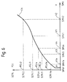
- Curve C6 in Figure 6 represents schematically the characteristic of the circuit of processing 15, that is to say the variation of the signal SCFc in function of the SMV signal, and therefore the variation of the setpoint power FCc as a function of the speed of rotation V of motor 2.
- this curve C6 has the same shape as curve C2b in figure 2 and, in particular, that the signal SCFc and therefore the power of FCc setpoint is zero when the SMV signal has the value SMVr corresponding to the engine idling speed Vr 2.
- circuit of signal processing 15 can also consist of advantageously by a read only memory.
- SCFc signal is applied to a first input a comparator circuit, designated by reference 16, which has a second input receiving the SCFb signal supplied by the multiplier circuit 12.
- the comparator 16 is arranged to produce a signal at its output SD switching which selectively takes a first SD1 state or a second state SD2 depending on whether the signal SCFb is lower or higher than the SCFc signal.
- the comparator 16 can be indifferently arranged so that the signal SD is in its first state SD1 or its second state SD2 when the signals SCFb and SCFc are equal.
- This comparator circuit 16 will not be described in detail because the skilled person will be able to realize it without difficulty in either of the various ways well known.
- the adjustment circuit 9 also includes a circuit switch, designated by reference 17, having two signal inputs receiving respectively the SCFb signal and the signal SCFc, a control input receiving the SD signal produced by comparator 16 and an output supplying the power setpoint signal SCFa applied to the integrator circuit 10c and mentioned above.
- This switch circuit 17 is arranged so that the SCFa signal is selectively equal to the SCFb signal or to the signal SCFc depending on whether the signal SD is in its first state SD1 or, respectively, its second state SD2.
- the signal SCFa is always equal to the smallest of the SCFb and SCFc signals, or both if these are equal.
- Circuits 16 and 17 will not be described in detail because they can both be done in different ways well known to specialists.
- the limitation signal SL therefore has its maximum value SLmax (see Figure 3).
- the characteristic of the circuit multiplier 12 is therefore the one represented by the line C4a of FIG. 4, and the signal SCFb produced by the multiplier circuit 12 has an equal value SCFb1 to the SCF1 value of the SCF signal.
- the set power FCb therefore has a value FCb1 equal to the value FC1 of the setpoint power FC.
- the signal SCFb having this value SCFb1, the signal SCV produced by processing circuit 13 has a value SCV1 ( Figure 5).
- the SMV signal for measuring the speed of rotation of the motor 2 therefore has a value SMV1 equal to the value SCV1 of the signal SCV, and the signal SP supplied by the comparator 14 has its SPf value.
- the value P1 of the mechanical power P provided by motor 2 is therefore represented by the ordinate of the point of curve C2b of figure 2 whose abscissa represents the value V1 of the speed of rotation of this motor 2.
- this power P1 is equal to the sum of the power of reference FCb1 mentioned above, which we will recall that it is equal in the case present at the setpoint power FC1, and powers DG and DC dissipated in generator 3 and in the circuit motor 10a 5.
- the electrical power E supplied by the generator 3 obviously has a value E1 equal to the difference between the power P1 and the power dissipated DG, and therefore also equal to the sum of the setpoint power FC1 and the DC power dissipated in the control circuit 10a.
- the SMV signal for measuring the speed of rotation V of motor 2 having the value SMV1 defined above, the signal SCFc produced by the signal processing circuit 15 has a value SCFc1, and the setpoint power FCc has a FCc1 value proportional to this SCFc1 value of this SCFc signal.
- this setpoint power FCc1 is equal to the difference between, on the one hand, the power P1 supplied by motor 2 and, on the other hand, the sum of DG and DC powers dissipated in generator 3 and in the control circuit 10a of the motor 5.
- this setpoint power FCc1 is equal to the set power FCb1, and that there is so likewise of the values SCFc1 and SCFb1 of the signals SCFc and, respectively, SCFb.
- the SCFa setpoint signal supplied by the switch 17 therefore has a value SCFa1 equal to this value SCFb1 of which we saw above that it is itself equal to the value SCF1 of the SCF signal produced by sensor 8b of the position of the accelerator pedal 8a.
- the electrical power F supplied by the control circuit 10a at motor 5 has a value F1 which is proportional to the value SCFa1 of the signal SCFa, and it is therefore equal to the setpoint power FC1 proportional to the value SCF1 of the SCF signal.
- This electrical power F1 therefore corresponds to the position of the accelerator pedal 8a.
- this electrical power F can have this F1 value
- the power electric E supplied by generator 3 to the command 10a has a value equal to the sum of this F1 value and the DC power dissipated in this circuit 10a.
- this electrical power E has a value E1 equal to the sum of the setpoint power FC1 and the power DC dissipated in the control circuit 10a, and that the power F1 is equal to this set power FC1.
- This situation which can be referred to as a situation of equilibrium, is maintained as long as the driver of vehicle 1 does not change the position of the accelerator pedal 8a and the slope of the ground on which road this vehicle 1 does not change.
- the speed of rotation W of the motor 5 being always higher than the speed WA, the signal SL always has its SLmax value, and the SCFb signal produced by the circuit multiplier 12 takes a value SCFb2 equal to the value SCF2 of the SCF signal ( Figure 4).
- the SCV signal produced by the processing circuit 13 takes a new SCV2 value greater than the SCV1 value previous ( Figure 5).
- the signal SP supplied by the comparator 14 therefore takes its maximum value SPmax, and the throttle valve of the carburetor 2a motor 2 fully opens.
- the mechanical power P supplied by the motor 2 therefore increases to a value P1 '( Figure 2).
- this increase in the power P has the effect of increasing the speed of rotation V of motor 2 up to speed V2 equal to the set speed VC2.
- the SMV signal for measuring this speed V remains lower than the new value SCV2 of the signal SCV, and the power setpoint signal SCFc produced by the processing circuit 15 remains less than the new SCFb2 value of the SCFb signal.
- Comparator 16 therefore gives the SD signal its second state SD2, so that the signal SCFa supplied by switch 17 is equal to signal SCFc, and that the setpoint power FCa at which the circuit servo 10 controls the electric power F supplied to motor 5 is equal to the target power FCc proportional to this signal SCFc.
- this target power FCc is always equal to the difference between the fraction f maximum mechanical power Pmax than motor 2 can deliver at the speed it spins and the sum dissipated powers DG and DC.
- the electrical power F supplied by the control circuit 10a to the motor 5, which is slaved to the setpoint power FCc since the value of the signal SCFa is equal to the value of the signal SCFc, is so less than the difference between this power mechanical P1 'and the sum of the dissipated powers DC and DC.
- This mechanical power P1 ' is therefore greater than that which the generator 3 absorbs, and the speed V of rotation of motor 2 increases until the SMV signal reaches the value SMV2 equal to the value SCV2 of the signal SCV.
- the signal SCFc setpoint obviously increases at the same time as the SMV signal and goes from its SCFc1 value to its SCFc2 value. But until it reaches this SCFc2 value, it stays below the SCFb signal, so the signal SCFa is always equal to this SCFc signal.
- the set power FCa at which the circuit 10 controls the electric power F supplied by the control circuit 10a of the motor 5 increases with the rotation speed V of the motor 2 and always remains equal to the difference between the mechanical power P that engine 2 would provide if the signal SP had its value SPf and the sum of the powers dissipated DG and DC.
- this setpoint power FCa remains below the set power FCb2 proportional to the SCFb2 value of the SCFb signal.
- the driver of vehicle 1 wishes to reduce the speed of it or keep it constant despite a decrease in the slope of the ground on which this vehicle is traveling 1, it moves the accelerator pedal 8a in the direction of its rest position to a position where the SCF signal takes, for example, an SCF3 value lower than the value SCF2 previous and proportional to a new FC3 setpoint power also lower than the previous FC2 setpoint power.
- the speed of rotation W of the motor 5 is obviously always higher than the speed WA, the signal SL has always its SLmax value, and the SCFb signal takes a SCFb3 value equal to the SCF3 value of the SCF signal (figure 4).
- the SCV signal takes a new SCV3 value lower than the previous SCV2 value ( Figure 5).
- the latter SCV3 value is obviously lower than the SMV2 value of the signal for measuring the speed of rotation V of this engine 2, at least initially.
- the signal SP supplied by the comparator 14 therefore takes its minimum value SPmin, and the throttle valve of the carburetor 2a motor closes completely.
- the mechanical power P supplied by the motor 2 therefore becomes practically zero, and the speed of rotation of this motor 2 decreases until it reaches the value V3 equal to the new setpoint value VC3.
- Comparator 16 therefore gives the signal SD its first state SD1, so that the signal SCFa supplied by the switch 17 immediately takes an equal SCFa3 value to the SCFb3 value of the SCFb signal.
- the setpoint power FCa at which the circuit servo 10 controls the electric power F supplied by the control circuit 10a to the motor 5 takes therefore, also immediately, the value FCa3 equal to the FCb3 value of the FCb setpoint power, which we have seen above that it is equal to the new FC3 value of the setpoint power FC.
- This situation also remains stable as long as the position of accelerator pedal 8a is not changed and / or that the slope of the ground on which the vehicle is traveling 1 do not change.
- the signal SCFb is therefore zero and the signal SCV a, for therefore, its value SCVr ( Figure 5).
- Motor 2 is running at its idling speed Vr, so that the SMV signal has its SMVr value equal to the SCVr value.
- the SCFc signal is therefore zero (FIG. 6) as well as the signal SCFa, and the control circuit 10a provides no power electric F to motor 5.
- the SMW speed measurement signal of rotation W of motor 5 is zero, and the signal SL limitation therefore has its minimum value SLmin ( Figure 3).
- the signal SL having its value SLmin, the value of SCFb signal is represented by the ordinate of the point of the line C4b of figure 4 whose abscissa is represented by the SCF1 value of the SCF signal.
- This signal value SCFb has been designated as SCFb1a.
- the processing circuit 13 In response to this value SCFb1a of the signal SCFb, the processing circuit 13 gives the signal SCV a value SCV1a, which is obviously greater than the value SCVr.
- the comparator 14 gives the signal SP its value SPmax, and the power mechanical P supplied by motor 2 takes the value Pr ' represented by the ordinate of the point of the curve C2a whose the abscissa represents the speed of rotation Vr.
- the mechanical power P increases and tends towards the value P1a represented by the ordinate of the point of the curve C2a whose abscissa represents the speed V1a.
- the signal SCFc therefore also begins to increase, but obviously remains, at least initially, lower than the SCFb1a value of the SCFb signal.
- the signal SCFa therefore has the same value as the signal SCFc and obviously increases at the same time as the latter.
- the electrical power F supplied by the command 10a to motor 5 therefore also increases, and from that it reaches a sufficient value, the vehicle 1 begins to move.
- the speed of rotation W of the motor 5 therefore begins to increase, as obviously the value of the SMW signal.
- the signal SL therefore increases, so that the signal SCFb also increases, as does the SCV signal.
- the SMV signal remains, at least at the start of this process, lower than the SCV signal, so the signal SP keeps its value SPmax and that the mechanical power P supplied by motor 2 keeps its Pmax value, which increases obviously at the same time as the rotational speed V of this motor 2 (curve C2a in FIG. 2).
- the SP signal keeps its SPmax value, and the power mechanical P provided by motor 2 is always equal to the maximum mechanical power Pmax that this motor 2 can provide at speed V where it rotates.
- the signal SCFa remains equal to the signal SCFc and the electrical power F supplied by the circuit command 10a to motor 5 is therefore always proportional to this signal SCFc and increases like the latter.
- the mechanical power P is therefore always higher to the sum of this electrical power F and dissipated powers DG and DC, so that the speed of rotation V of motor 2 continues to increase.
- the signal SL has taken its value SLmax
- the signal SCFb has the value SCFb1 equal to the value SCF1 of the signal SCF
- the signal SCFa obviously also has this value SCF1.
- Vehicle 1 is therefore in a situation similar to the one described above.
- vehicle speed 1 is such that the rotation speed W of motor 5 has a lower value at the speed WA, for example the value Wx indicated at the Figure 3, the corresponding value SLx of the signal SL is still lower than its maximum value SLmax.
- the characteristic of the multiplier circuit 12 is therefore represented, in this case, by the line C4x of the Figure 4, and the SCFbx value of the SCFb signal is given by the ordinate of the point of this straight line C4x whose abscissa represents the SCF1 value of the SCF signal.
- the signal SCV therefore has the corresponding value SCVx ( Figure 5) and the SMV signal has the value SMVx equal to this SCVx value.
- Motor 2 therefore provides mechanical power Px shown in Figure 2, and the signal SCFc has the value SCFcx equal to the SCFbx value of the SCFb signal.
- the signal SCFa therefore has a value SCFax equal to this last value SCFbx, and the electrical power F supplied by the circuit 10a to motor 2 has an Fx value proportional to this SCFbx value.
- a vehicle according to the present invention has a behavior very close to that of conventional vehicles whose traction motor is an internal combustion engine and that the danger that can be created in vehicles known to the same kind, the delay between the moment when their driver presses their accelerator pedal the instant the electrical power supplied to their motor traction increases is removed.
- the components of the control 10a which are crossed by the current absorbed by the traction motor 5 can have a nominal current smaller, and therefore a smaller footprint and a lower price, all other things being equal, than corresponding components of known vehicles.
- the comparison circuit 14 so that the signal SP of carburetor 2a control of engine 2 does not change abruptly as described above but at gradually, between its values SPmax, SPf and SPmin.
- the present invention is not limited to the case described above of a vehicle having only one driving wheel, but that it applies obviously also in the case of vehicles having several drive wheels driven by a traction motor common, as well as in the case of vehicles with several traction motors each driving one or more drive wheels.
Landscapes
- Engineering & Computer Science (AREA)
- Transportation (AREA)
- Mechanical Engineering (AREA)
- Chemical & Material Sciences (AREA)
- Combustion & Propulsion (AREA)
- Power Engineering (AREA)
- Automation & Control Theory (AREA)
- Polymers With Sulfur, Phosphorus Or Metals In The Main Chain (AREA)
- Electric Propulsion And Braking For Vehicles (AREA)
- Hybrid Electric Vehicles (AREA)
- Auxiliary Drives, Propulsion Controls, And Safety Devices (AREA)
Description
- un premier moteur constitué par un moteur à combustion interne pour produire une puissance mécanique;
- des moyens d'asservissement de vitesse comportant des premiers moyens de mesure couplés audit premier moteur pour fournir un premier signal de mesure représentatif de la vitesse de rotation dudit premier moteur et répondant à un signal de consigne de vitesse représentatif d'une vitesse de rotation de consigne pour asservir ladite vitesse de rotation dudit premier moteur à ladite vitesse de rotation de consigne;
- un dispositif de commande comportant un organe de commande actionnable par un conducteur dudit véhicule et un détecteur couplé audit organe de commande pour fournir un premier signal de consigne de puissance représentatif de la position dudit organe de commande et d'une première puissance de consigne;
- un générateur couplé mécaniquement audit premier moteur pour produire une première puissance électrique en réponse à ladite puissance mécanique;
- une roue motrice;
- un deuxième moteur constitué par un moteur électrique couplé mécaniquement à ladite roue motrice; et
- des moyens de réglage répondant à ladite première puissance électrique pour fournir une deuxième puissance électrique audit deuxième moteur et répondant audit premier signal de consigne de puissance pour produire ledit signal de consigne de vitesse et pour asservir ladite deuxième puissance électrique à ladite première puissance de consigne.
- des moyens d'asservissement de vitesse comportant des premiers moyens de mesure couplés audit premier moteur pour fournir un premier signal de mesure représentatif de la vitesse de rotation dudit premier moteur et répondant à un signal de consigne de vitesse représentatif d'une vitesse de rotation de consigne pour asservir ladite vitesse de rotation dudit premier moteur à ladite vitesse de rotation de consigne;
- un dispositif de commande comportant un organe de commande actionnable par un conducteur dudit véhicule et un détecteur couplé audit organe de commande pour fournir un premier signal de consigne de puissance représentatif de la position dudit organe de commande et d'une première puissance de consigne;
- un générateur couplé mécaniquement audit premier moteur pour produire une première puissance électrique en réponse à ladite puissance mécanique;
- une roue motrice;
- un deuxième moteur constitué par un moteur électrique couplé mécaniquement a ladite roue motrice; et
- des moyens de réglage répondant à ladite première
puissance électrique pour fournir une deuxième puissance
électrique audit deuxième moteur et répondant audit
premier signal de consigne de puissance pour produire
ledit signal de consigne de vitesse et pour asservir
ladite deuxième puissance électrique à ladite première
puissance de consigne;
et qui caractérisé par le fait que ledit véhicule comporte en outre des deuxièmes moyens de mesure couplés audit deuxième moteur pour fournir un deuxième signal de mesure représentatif de la vitesse de rotation dudit deuxième moteur;
et par le fait que lesdits moyens de réglage comportent : - des moyens d'asservissement de puissance répondant à un deuxième signal de consigne de puissance représentatif d'une deuxième puissance de consigne pour asservir ladite deuxième puissance électrique à ladite deuxième puissance de consigne;
- des moyens de sécurité répondant audit premier signal de consigne de puissance et audit deuxième signal de mesure pour fournir un troisième signal de consigne de puissance représentatif d'une troisième puissance de consigne et agencés de manière que ledit troisième signal de consigne de puissance a une valeur telle que ladite troisième puissance de consigne est au plus égale à la puissance électrique maximale que lesdits moyens d'asservissement peuvent fournir sans dommage audit deuxième moteur;
- des premiers moyens de traitement de signal répondant audit troisième signal de consigne de puissance pour fournir ledit signal de consigne de vitesse et agencés de manière que ledit signal de consigne de vitesse a une valeur telle que, lorsque la vitesse de rotation dudit premier moteur est égale à ladite vitesse de consigne, une fraction déterminée de la puissance mécanique maximale que ledit premier moteur peut fournir est égale à la somme de ladite troisième puissance de consigne et des puissances dissipées dans ledit générateur et dans lesdits moyens d'asservissement de puissance;
- des deuxièmes moyens de traitement de signal répondant audit premier signal de mesure pour fournir un quatrième signal de consigne de puissance représentatif d'une quatrième puissance de consigne et agencés de manière que ledit quatrième signal de consigne de puissance a une valeur telle que ladite quatrième puissance de consigne est égale à la différence entre ladite fraction déterminée de ladite puissance mécanique maximale et lesdites puissances dissipées; et
- des moyens de sélection répondant audit troisième signal de consigne de puissance et audit quatrième signal de consigne de puissance pour fournir ledit deuxième signal de consigne de puissance et agencés de manière que ledit deuxième signal de consigne de puissance a une valeur telle que ladite deuxième puissance de consigne est égale à la plus petite desdites troisième puissance de consigne et quatrième puissance de consigne.
- la figure 1 est un schéma-bloc d'une forme d'exécution du véhicule selon la présente invention;
- la figure 2 est un diagramme représentant schématiquement la variation de la puissance mécanique P fournie par un moteur à explosion en fonction de sa vitesse de rotation V pour deux valeurs différentes du signal de commande SP de son carburateur; et
- les figures 3 à 6 sont des diagrammes qui illustrent schématiquement les caractéristiques de divers composants du circuit de la figure 1.
Claims (5)
- Véhicule automobile (1) comportant :un premier moteur (2) constitué par un moteur à combustion interne pour produire une puissance mécanique (P) en fonction de la vitesse de rotation dudit premier moteur (2);des moyens d'asservissement de vitesse (2a,4,14) comportant des premiers moyens de mesure (4) couplés audit premier moteur (2) pour fournir un premier signal de mesure (SMV) représentatif de la vitesse de rotation (V) dudit premier moteur (2) et répondant à un signal de consigne de vitesse (SCV) représentatif d'une vitesse de rotation de consigne (VC) pour asservir ladite vitesse de rotation (V) dudit premier moteur (2) à ladite vitesse de rotation de consigne (VC);un dispositif de commande (8) comportant un organe de commande (8a) actionnable par un conducteur dudit véhicule (1) et un détecteur (8b) couplé audit organe de commande (8a) pour fournir un premier signal de consigne de puissance (SCF) représentatif de la position dudit organe de commande (8a) et d'une première puissance de consigne (FC);un générateur (3) couplé mécaniquement audit premier moteur (2) pour produire une première puissance électrique (E) en réponse à ladite puissance mécanique (P);une roue motrice (6);un deuxième moteur (5) constitué par un moteur électrique couplé mécaniquement à ladite roue motrice (6); etdes moyens de réglage (9) répondant à ladite première puissance électrique (E) pour fournir une deuxième puissance électrique (F) audit deuxième moteur (5) et répondant audit premier signal de consigne de puissance (SCF) pour produire ledit signal de consigne de vitesse (SCV) et pour asservir ladite deuxième puissance électrique (F) à ladite première puissance de consigne (FC);
caractérisé par le fait que ledit véhicule (1) comporte en outre des deuxièmes moyens de mesure (7) couplés audit deuxième moteur (5) pour fournir un deuxième signal de mesure (SMW) représentatif de la vitesse de rotation (W) dudit deuxième moteur (5);
et par le fait que lesdits moyens de réglage (9) comportent :des moyens d'asservissement de puissance (10) répondant à un deuxième signal de consigne de puissance (SCFa) représentatif d'une deuxième puissance de consigne (FCa) pour asservir ladite deuxième puissance électrique (F) à ladite deuxième puissance de consigne (FCa);des moyens de sécurité (11,12) répondant audit premier signal de consigne de puissance (SCF) et audit deuxième signal de mesure (SMW) pour fournir un troisième signal de consigne de puissance (SCFb) représentatif d'une troisième puissance de consigne (FCb) et agencés de manière que ledit troisième signal de consigne de puissance (SCFb) a une valeur telle que ladite troisième puissance de consigne (FCv) est au plus égale à la puissance électrique maximale (FM) que lesdits moyens d'asservissement (10) peuvent fournir sans dommage audit deuxième moteur (5);des premiers moyens de traitement de signal (13) répondant audit troisième signal de consigne de puissance (SCFb) pour fournir ledit signal de consigne de vitesse (SCV) et agencés de manière que ledit signal de consigne de vitesse (SCV) a une valeur telle que, lorsque la vitesse de rotation (V) dudit premier moteur (2) est égale à ladite vitesse de consigne (VC), une fraction déterminée (f) de la puissance mécanique maximale (Pmax), qui est une fonction de la vitesse de rotation dudit premier moteur (2), est égale à la somme de ladite troisième puissance de consigne (FCb) et des puissances dissipées (DG,DC) dans ledit générateur (3) et dans lesdits moyens d'asservissement de puissance (10);des deuxièmes moyens de traitement de signal (15) répondant audit premier signal de mesure (SMV) pour fournir un quatrième signal de consigne de puissance (SCFc) représentatif d'une quatrième puissance de consigne (FCc) et agencés de manière que ledit quatrième signal de consigne de puissance (SCFc) a une valeur telle que ladite quatrième puissance de consigne (FCc) est égale à la différence entre ladite fraction déterminée (f) de ladite puissance mécanique maximale (Pmax) et lesdites puissances dissipées (DG,DC); etdes moyens de sélection (16,17) répondant audit troisième signal de consigne de puissance (SCFb) et audit quatrième signal de consigne de puissance (SCFc) pour fournir ledit deuxième signal de consigne de puissance (SCFa) et agencés de manière que ledit deuxième signal de consigne de puissance (SCFa) a une valeur telle que ladite deuxième puissance de consigne (FCa) est égale à la plus petite desdites troisième puissance de consigne (FCb) et quatrième puissance de consigne (FCc). - Véhicule automobile (1) selon la revendication 1, caractérisé par le fait que lesdits moyens de sécurité (11,12) comportent des troisièmes moyens de traitement de signal (11) répondant audit deuxième signal de mesure (SMW) pour fournir un signal de limitation (SL) représentatif de ladite puissance électrique maximale (FM) et des moyens de calcul (12) répondant audit premier signal de consigne de puissance (SCF) et audit signal de limitation (SL) pour produire ledit troisième signal de consigne de puissance (SCFb).
- Véhicule automobile (1) selon la revendication 1, caractérisé par le fait que lesdits moyens d'asservissement (2a,4,14) comportent en outre :des moyens de commande (2a) de ladite puissance mécanique (P) répondant à un signal de commande de puissance (SP) et agencés de manière que ladite puissance mécanique (P) est égale à ladite puissance mécanique maximale (Pmax), égale à ladite fraction déterminée (f) de ladite puissance mécanique maximale (Pmax) et sensiblement nulle selon que ledit signal de commande de puissance (SP) a respectivement une première valeur (SPmax), une deuxième valeur (SPf) et une troisième valeur (SPmin); etdes moyens de comparaison (14) répondant audit signal de consigne de vitesse (SCV) et audit premier signal de mesure (SMV) pour produire ledit signal de commande de puissance (SP) et agencé de manière que ledit signal de commande de puissance (SP) a ladite première valeur (SPmax), ladite deuxième valeur (SPf) et ladite troisième valeur (SPmin) selon que ledit signal de consigne de vitesse (SCV) est respectivement supérieur, égal et inférieur audit premier signal de mesure (SMV).
- Véhicule automobile (1) selon la revendication 1, caractérisé par le fait que lesdits moyens de sélection (16,17) comportent :des moyens de comparaison (16) répondant audit troisième signal de consigne de puissance (SCFb) et audit quatrième signal de consigne de puissance (SCFc) pour fournir un signal de commutation (SD) et agencés de manière que ledit signal de commutation (SD) a un premier état (SD1) et un deuxième état (SD2) selon que ledit troisième signal de consigne de puissance (SCFb) est respectivement inférieur et supérieur audit quatrième signal de consigne de puissance (SCFc); etdes moyens de commutation (17) répondant audit signal de commutation (SD), audit troisième signal de consigne de puissance (SCFb) et audit quatrième signal de consigne de puissance (SXFc) pour fournir ledit deuxième signal de consigne de puissance (SCFa) et agencés de manière que ledit deuxième signal de consigne de puissance (SCFa) a une valeur telle que ladite deuxième puissance de consigne (FCa) est égale à ladite troisième puissance de consigne (FCb) ou à ladite quatrième puissance de consigne (FCc) selon que ledit signal de commutation (SD) est respectivement dans son premier état (SD1) et dans son deuxième état (SD2).
- Véhicule automobile (1) selon la revendication 1, caractérisé par le fait que ladite fraction déterminée (f) est sensiblement égale à 80%.
Applications Claiming Priority (4)
| Application Number | Priority Date | Filing Date | Title |
|---|---|---|---|
| CH01180/94A CH689692A5 (fr) | 1994-04-19 | 1994-04-19 | Véhicule hybride. |
| CH1180/94 | 1994-04-19 | ||
| FR9405532A FR2719526B1 (fr) | 1994-05-05 | 1994-05-05 | Véhicule automobile à moteur thermique et propulsion électrique asservie en puissance. |
| FR9405532 | 1994-05-05 |
Publications (2)
| Publication Number | Publication Date |
|---|---|
| EP0678414A1 EP0678414A1 (fr) | 1995-10-25 |
| EP0678414B1 true EP0678414B1 (fr) | 1998-07-08 |
Family
ID=25686914
Family Applications (1)
| Application Number | Title | Priority Date | Filing Date |
|---|---|---|---|
| EP95105340A Expired - Lifetime EP0678414B1 (fr) | 1994-04-19 | 1995-04-08 | Véhicule hybride |
Country Status (3)
| Country | Link |
|---|---|
| EP (1) | EP0678414B1 (fr) |
| AT (1) | ATE168078T1 (fr) |
| DE (1) | DE69503291T2 (fr) |
Families Citing this family (6)
| Publication number | Priority date | Publication date | Assignee | Title |
|---|---|---|---|---|
| FR2743343B1 (fr) * | 1996-01-05 | 1998-02-13 | Smh Management Services Ag | Systeme d'entrainement pour vehicule automobile a propulsion hybride et son procede de commande |
| FR2783768B1 (fr) * | 1998-09-28 | 2000-11-24 | Renault | Procede de commande d'un vehicule hybride a transmission electrique serie |
| FR2791195B1 (fr) * | 1999-03-15 | 2001-05-18 | Renault | Systeme de commande d'un groupe generateur electrique |
| JP3539358B2 (ja) * | 2000-06-09 | 2004-07-07 | 日産自動車株式会社 | 車両の駆動力制御装置 |
| HUP0500296A2 (en) | 2005-03-11 | 2008-04-28 | Zsolt Hegedues | Hybrid driven vehicle |
| DE102014219004A1 (de) * | 2014-09-22 | 2016-03-24 | Continental Teves Ag & Co. Ohg | Signalverarbeitungsvorrichtung zur Verarbeitung eines Messsignals in einem Kraftfahrzeug |
Family Cites Families (3)
| Publication number | Priority date | Publication date | Assignee | Title |
|---|---|---|---|---|
| DE4133060C2 (de) * | 1991-10-04 | 1995-08-31 | Mannesmann Ag | Antriebsanordnung für ein Kraftfahrzeug |
| DE4133059A1 (de) * | 1991-10-04 | 1993-04-08 | Mannesmann Ag | Antriebsanordnung fuer ein kraftfahrzeug |
| DE4205770C2 (de) * | 1992-02-21 | 1994-05-05 | Mannesmann Ag | Fahrzeug mit Verbrennungsmotor, elektrischem Generator und Elektromotor |
-
1995
- 1995-04-08 EP EP95105340A patent/EP0678414B1/fr not_active Expired - Lifetime
- 1995-04-08 AT AT95105340T patent/ATE168078T1/de active
- 1995-04-08 DE DE69503291T patent/DE69503291T2/de not_active Expired - Fee Related
Also Published As
| Publication number | Publication date |
|---|---|
| DE69503291T2 (de) | 1999-03-18 |
| ATE168078T1 (de) | 1998-07-15 |
| EP0678414A1 (fr) | 1995-10-25 |
| DE69503291D1 (de) | 1998-08-13 |
Similar Documents
| Publication | Publication Date | Title |
|---|---|---|
| CH689692A5 (fr) | Véhicule hybride. | |
| EP0652835B1 (fr) | Vehicule automobile a traction electrique | |
| EP0414782B1 (fr) | Boite de vitesses a variation continue par engrenages | |
| FR2898742A1 (fr) | Dispositif de commande permettant une commande economique et fiable d'un generateur electrique. | |
| FR2780921A1 (fr) | Dispositif de sortie motrice et son procede de controle et vehicule hybride actionne par le dispositif de sortie motrice | |
| CH687307A5 (fr) | Ensemble de propulsion d'un véhicule. | |
| EP0782941A1 (fr) | Procédé et dispositif pour régler la répartition de la puissance électrique dans un véhicule automobile, notamment à propulsion hybride | |
| FR2732652A1 (fr) | Vehicule electro-hydraulique a recuperation d'energie | |
| FR2520892A1 (fr) | Systeme regulateur de la vitesse d'un moteur | |
| EP0576947B1 (fr) | Système moteur d'un véhicule du type électrique | |
| EP0786369A1 (fr) | Procédé et dispositif de régulation commune de plusieurs moteurs électriques entraînant les roues motrices d'un véhicule automobile | |
| EP0678414B1 (fr) | Véhicule hybride | |
| FR3012399A1 (fr) | Systeme de charge de vehicule | |
| EP1224092A1 (fr) | Procede de commande d'un vehicule hybride | |
| FR2465884A1 (fr) | Groupe propulseur pour vehicule automobile utilisant un moteur thermique jusqu'aux plus bas regimes | |
| EP1402202A1 (fr) | Appareil de transmission de vitesses | |
| FR3083338A1 (fr) | Procede d'emulation de soubresauts par la commande d'une machine electrique tournante integree dans une chaine de transmission de vehicule automobile | |
| FR2719526A1 (fr) | Véhicule automobile à moteur thermique et propulsion électrique asservie en puissance. | |
| EP1542882A2 (fr) | Procede et dispositif de transmission de puissance pour un vehicule hybride | |
| EP1452383B1 (fr) | Système de régulation mécanique du dispositif de transmission de mouvement pour un véhicule automobile | |
| FR2875201A1 (fr) | Procede de commande a plusieurs modes de fonctionnement d'une transmission automatisee pour un vehicule automobile, notamment pour un avancement au ralenti du vehicule automobile avec frein active et dispositif correspondant | |
| FR2875448A1 (fr) | Systeme de controle du fonctionnement de moyens de motorisation hybride pour vehicule automobile | |
| EP1174304A1 (fr) | Dispositif de transmission électronique de couple sans batterie de puissance | |
| FR2842870A1 (fr) | Procede et dispositif pour la commande d'une unite d'entrainement d'un vehicule | |
| FR2780350A1 (fr) | Vehicule automobile comportant un dispositif de regulation automatique de la vitesse |
Legal Events
| Date | Code | Title | Description |
|---|---|---|---|
| PUAI | Public reference made under article 153(3) epc to a published international application that has entered the european phase |
Free format text: ORIGINAL CODE: 0009012 |
|
| AK | Designated contracting states |
Kind code of ref document: A1 Designated state(s): AT BE DE ES GB IT NL SE |
|
| 17P | Request for examination filed |
Effective date: 19960111 |
|
| GRAG | Despatch of communication of intention to grant |
Free format text: ORIGINAL CODE: EPIDOS AGRA |
|
| 17Q | First examination report despatched |
Effective date: 19970808 |
|
| GRAG | Despatch of communication of intention to grant |
Free format text: ORIGINAL CODE: EPIDOS AGRA |
|
| GRAG | Despatch of communication of intention to grant |
Free format text: ORIGINAL CODE: EPIDOS AGRA |
|
| GRAH | Despatch of communication of intention to grant a patent |
Free format text: ORIGINAL CODE: EPIDOS IGRA |
|
| GRAH | Despatch of communication of intention to grant a patent |
Free format text: ORIGINAL CODE: EPIDOS IGRA |
|
| GRAA | (expected) grant |
Free format text: ORIGINAL CODE: 0009210 |
|
| AK | Designated contracting states |
Kind code of ref document: B1 Designated state(s): AT BE DE ES GB IT NL SE |
|
| PG25 | Lapsed in a contracting state [announced via postgrant information from national office to epo] |
Ref country code: NL Free format text: LAPSE BECAUSE OF FAILURE TO SUBMIT A TRANSLATION OF THE DESCRIPTION OR TO PAY THE FEE WITHIN THE PRESCRIBED TIME-LIMIT Effective date: 19980708 Ref country code: ES Free format text: THE PATENT HAS BEEN ANNULLED BY A DECISION OF A NATIONAL AUTHORITY Effective date: 19980708 Ref country code: AT Free format text: LAPSE BECAUSE OF FAILURE TO SUBMIT A TRANSLATION OF THE DESCRIPTION OR TO PAY THE FEE WITHIN THE PRESCRIBED TIME-LIMIT Effective date: 19980708 |
|
| REF | Corresponds to: |
Ref document number: 168078 Country of ref document: AT Date of ref document: 19980715 Kind code of ref document: T |
|
| REF | Corresponds to: |
Ref document number: 69503291 Country of ref document: DE Date of ref document: 19980813 |
|
| ITPR | It: changes in ownership of a european patent |
Owner name: C.BIO NOME EPO REG.92;THE SWATCH GROUP MANAGEMENT |
|
| PG25 | Lapsed in a contracting state [announced via postgrant information from national office to epo] |
Ref country code: SE Free format text: LAPSE BECAUSE OF FAILURE TO SUBMIT A TRANSLATION OF THE DESCRIPTION OR TO PAY THE FEE WITHIN THE PRESCRIBED TIME-LIMIT Effective date: 19981008 |
|
| GBT | Gb: translation of ep patent filed (gb section 77(6)(a)/1977) |
Effective date: 19981012 |
|
| NLV1 | Nl: lapsed or annulled due to failure to fulfill the requirements of art. 29p and 29m of the patents act | ||
| RAP2 | Party data changed (patent owner data changed or rights of a patent transferred) |
Owner name: THE SWATCH GROUP MANAGEMENT SERVICES AG |
|
| PLBE | No opposition filed within time limit |
Free format text: ORIGINAL CODE: 0009261 |
|
| STAA | Information on the status of an ep patent application or granted ep patent |
Free format text: STATUS: NO OPPOSITION FILED WITHIN TIME LIMIT |
|
| 26N | No opposition filed | ||
| PGFP | Annual fee paid to national office [announced via postgrant information from national office to epo] |
Ref country code: GB Payment date: 20010330 Year of fee payment: 7 |
|
| PGFP | Annual fee paid to national office [announced via postgrant information from national office to epo] |
Ref country code: DE Payment date: 20010406 Year of fee payment: 7 |
|
| PGFP | Annual fee paid to national office [announced via postgrant information from national office to epo] |
Ref country code: BE Payment date: 20010516 Year of fee payment: 7 |
|
| REG | Reference to a national code |
Ref country code: GB Ref legal event code: IF02 |
|
| PG25 | Lapsed in a contracting state [announced via postgrant information from national office to epo] |
Ref country code: GB Free format text: LAPSE BECAUSE OF NON-PAYMENT OF DUE FEES Effective date: 20020408 |
|
| PG25 | Lapsed in a contracting state [announced via postgrant information from national office to epo] |
Ref country code: BE Free format text: LAPSE BECAUSE OF NON-PAYMENT OF DUE FEES Effective date: 20020430 |
|
| PG25 | Lapsed in a contracting state [announced via postgrant information from national office to epo] |
Ref country code: DE Free format text: LAPSE BECAUSE OF NON-PAYMENT OF DUE FEES Effective date: 20021101 |
|
| GBPC | Gb: european patent ceased through non-payment of renewal fee |
Effective date: 20020408 |
|
| PG25 | Lapsed in a contracting state [announced via postgrant information from national office to epo] |
Ref country code: IT Free format text: LAPSE BECAUSE OF NON-PAYMENT OF DUE FEES;WARNING: LAPSES OF ITALIAN PATENTS WITH EFFECTIVE DATE BEFORE 2007 MAY HAVE OCCURRED AT ANY TIME BEFORE 2007. THE CORRECT EFFECTIVE DATE MAY BE DIFFERENT FROM THE ONE RECORDED. Effective date: 20050408 |