EP0678630A2 - Einpunktarmatur - Google Patents
Einpunktarmatur Download PDFInfo
- Publication number
- EP0678630A2 EP0678630A2 EP95810253A EP95810253A EP0678630A2 EP 0678630 A2 EP0678630 A2 EP 0678630A2 EP 95810253 A EP95810253 A EP 95810253A EP 95810253 A EP95810253 A EP 95810253A EP 0678630 A2 EP0678630 A2 EP 0678630A2
- Authority
- EP
- European Patent Office
- Prior art keywords
- point fitting
- casing
- inner body
- fitting according
- fitting
- Prior art date
- Legal status (The legal status is an assumption and is not a legal conclusion. Google has not performed a legal analysis and makes no representation as to the accuracy of the status listed.)
- Granted
Links
- 230000008878 coupling Effects 0.000 claims abstract description 11
- 238000010168 coupling process Methods 0.000 claims abstract description 11
- 238000005859 coupling reaction Methods 0.000 claims abstract description 11
- XLYOFNOQVPJJNP-UHFFFAOYSA-N water Substances O XLYOFNOQVPJJNP-UHFFFAOYSA-N 0.000 claims abstract description 8
- 238000012423 maintenance Methods 0.000 description 2
- 239000000565 sealant Substances 0.000 description 2
- 238000010276 construction Methods 0.000 description 1
- 238000009434 installation Methods 0.000 description 1
- 238000009413 insulation Methods 0.000 description 1
- 238000004519 manufacturing process Methods 0.000 description 1
- 238000000034 method Methods 0.000 description 1
- 238000003825 pressing Methods 0.000 description 1
- 238000010079 rubber tapping Methods 0.000 description 1
- 238000007789 sealing Methods 0.000 description 1
Images

Classifications
-
- E—FIXED CONSTRUCTIONS
- E03—WATER SUPPLY; SEWERAGE
- E03C—DOMESTIC PLUMBING INSTALLATIONS FOR FRESH WATER OR WASTE WATER; SINKS
- E03C1/00—Domestic plumbing installations for fresh water or waste water; Sinks
- E03C1/02—Plumbing installations for fresh water
- E03C1/04—Water-basin installations specially adapted to wash-basins or baths
- E03C1/042—Arrangements on taps for wash-basins or baths for connecting to the wall
-
- E—FIXED CONSTRUCTIONS
- E03—WATER SUPPLY; SEWERAGE
- E03C—DOMESTIC PLUMBING INSTALLATIONS FOR FRESH WATER OR WASTE WATER; SINKS
- E03C1/00—Domestic plumbing installations for fresh water or waste water; Sinks
- E03C1/02—Plumbing installations for fresh water
- E03C1/04—Water-basin installations specially adapted to wash-basins or baths
- E03C1/0404—Constructional or functional features of the spout
-
- Y—GENERAL TAGGING OF NEW TECHNOLOGICAL DEVELOPMENTS; GENERAL TAGGING OF CROSS-SECTIONAL TECHNOLOGIES SPANNING OVER SEVERAL SECTIONS OF THE IPC; TECHNICAL SUBJECTS COVERED BY FORMER USPC CROSS-REFERENCE ART COLLECTIONS [XRACs] AND DIGESTS
- Y10—TECHNICAL SUBJECTS COVERED BY FORMER USPC
- Y10T—TECHNICAL SUBJECTS COVERED BY FORMER US CLASSIFICATION
- Y10T137/00—Fluid handling
- Y10T137/6851—With casing, support, protector or static constructional installations
- Y10T137/6966—Static constructional installations
- Y10T137/6969—Buildings
- Y10T137/698—Wall
-
- Y—GENERAL TAGGING OF NEW TECHNOLOGICAL DEVELOPMENTS; GENERAL TAGGING OF CROSS-SECTIONAL TECHNOLOGIES SPANNING OVER SEVERAL SECTIONS OF THE IPC; TECHNICAL SUBJECTS COVERED BY FORMER USPC CROSS-REFERENCE ART COLLECTIONS [XRACs] AND DIGESTS
- Y10—TECHNICAL SUBJECTS COVERED BY FORMER USPC
- Y10T—TECHNICAL SUBJECTS COVERED BY FORMER US CLASSIFICATION
- Y10T137/00—Fluid handling
- Y10T137/8593—Systems
- Y10T137/86268—With running joint between movable parts of system
-
- Y—GENERAL TAGGING OF NEW TECHNOLOGICAL DEVELOPMENTS; GENERAL TAGGING OF CROSS-SECTIONAL TECHNOLOGIES SPANNING OVER SEVERAL SECTIONS OF THE IPC; TECHNICAL SUBJECTS COVERED BY FORMER USPC CROSS-REFERENCE ART COLLECTIONS [XRACs] AND DIGESTS
- Y10—TECHNICAL SUBJECTS COVERED BY FORMER USPC
- Y10T—TECHNICAL SUBJECTS COVERED BY FORMER US CLASSIFICATION
- Y10T137/00—Fluid handling
- Y10T137/8593—Systems
- Y10T137/877—With flow control means for branched passages
- Y10T137/87829—Biased valve
- Y10T137/87837—Spring bias
-
- Y—GENERAL TAGGING OF NEW TECHNOLOGICAL DEVELOPMENTS; GENERAL TAGGING OF CROSS-SECTIONAL TECHNOLOGIES SPANNING OVER SEVERAL SECTIONS OF THE IPC; TECHNICAL SUBJECTS COVERED BY FORMER USPC CROSS-REFERENCE ART COLLECTIONS [XRACs] AND DIGESTS
- Y10—TECHNICAL SUBJECTS COVERED BY FORMER USPC
- Y10T—TECHNICAL SUBJECTS COVERED BY FORMER US CLASSIFICATION
- Y10T137/00—Fluid handling
- Y10T137/9464—Faucets and spouts
Definitions
- the invention relates to a single-point valve with the features specified in the preamble of claim 1.
- the purpose of the invention is to create a single-point fitting which is inexpensive to manufacture and which can be quickly and easily assembled and completed on site.
- the visible parts of the single-point valve should be replaced quickly and inexpensively during maintenance.
- EP 0 392 176 shows such an arrangement in which the fitting body which carries the mixing device is designed as a one-piece part with the outlet and is equipped with a multi-part rosette.
- the valve body has a flange with several through holes, through which it is screwed to a connecting element in a positive manner in the direction of rotation.
- discharge fittings as modular building block systems, in that a base body is preferably combined with several discharge pieces of different lengths. It is also known that these outlet pieces are rotatably mounted on the connection to the valve body and that these pivot bearings have swivel angle limits.
- CH 673 689 shows a fitting in which such rotatably mounted covers are present and which can simultaneously serve as a pivotable holder for a flexible spout.
- the single-point fitting contains, among other things, the operating element 1, the casing 2, the inner body 3, which is preferably formed in one piece, the union nut 4 and a snap ring 5 which is seated in an annular groove 5a of the inner body 3 and is secured by the securing ring 6.
- the union nut sits with an axial play z approximately corresponding to its length on a shoulder of the inner body 3 and connects the single-point fitting via the snap ring 5 and the locking ring 6 and via seals 25 in a rotationally non-positive manner and tightly to the fitting connecting element 7.
- This arrangement means that the fastening means 4 , 5, 6 can be removed quickly and easily in the mounting direction of the valve against the valve connecting element 7.
- the valve connector 7 consists of a housing 26 and an insert 27 rotatably inserted in the housing 26 with two channels 28 for cold and hot water, which are aligned with corresponding channels 29 of the inner body 3.
- two pins 30 formed on the insert 27 engage in corresponding bores 31 of the inner body 3. It is thereby achieved that the housing 26 can be mounted in the wall in any rotational position.
- 27 hot and cold water connections can be swapped by turning the insert. The non-positive connection between the inner body 3 and the connecting member 7 therefore facilitates the installation of the supply lines.
- the rosette 8 carries in its inside means for water-tight sealing against the wall 23 on the one hand and against the casing 2 of the single-point fitting on the other hand, as well as a screw 10.
- This screw 10 spreads the seal 9a frictionally against the casing 2 when screwed in and thus serves as a fixing element for the rosette on the single-point fitting to keep the sealant under the rosette for years.
- the type of attachment of the union nut 4 by means of a snap ring 5 and locking ring 6 allows on the one hand a smaller diameter of the fitting body 2 and 3 than that of the union nut and on the other hand the aforementioned quick and easy assembly of the union nut 4 after the rosette, designed as a one-piece assembly with loose screw 10 has been pushed onto the casing 2.
- the rosette can be pushed as far as possible on the casing 2 in the direction of the operating element 1. This creates the necessary space for the appropriate assembly wrench for the purpose of tool attack in the longitudinal grooves 32 of the union nut 4 in the interior of the wall.
- the rosette 8 can be pushed approximately up to the operating member 1 onto the valve head when the connection to the valve connecting element 7 is carried out with a suitably designed geometry, which is particularly advantageous.
- the inner body 3 contains the feed lines 29 for hot and cold water from the valve connection element 7 to the mixing element 11 containing the shut-off and mixing device, which is connected in a rotationally fixed manner by means of a cam 12 to the inner body 3, and the mixed water outlet 13, which leads to the coupling part in FIGS then leads to the outlet 14. He also wears the casing 2, which can be pushed onto the inner body 3 from both sides via an O-ring brake 15.
- the casing can be slid on both sides has the particular advantage that the inner body is already pre-assembled during factory assembly Valve head (control element 1 and mixing element 11), and with the head sheathing 17a and 17b, but without connecting parts (union nut 4, snap ring 5 and locking ring 6), without sheathing 2, without a rosette and without a coupling part according to FIG. 2, can be checked for function and tightness . This means that any leaks on the inner body are immediately visible.
- both the casing 2 and the one-piece rosette 8 can be easily removed to the front in order to carry out maintenance.
- the water does not need to be turned off and / or the single-point fitting has to be dismantled from the connection element 7.
- the casing 2 is held on the inner body by means of the screw 16 so as to be non-rotatable and non-slip, which in turn is absolutely necessary for the permanent pressing of the sealant 9 under the rosette 8 and to maintain the rotatability of the valve head 1, 17, 17a when the valve is operated .
- the screw head of the screw 16 already produces this holder due to the height H of its screw head in the partially screwed-in state, which brings about the advantages of the following explanations:
- Fig. 2 the coupling part to the outlet 14, 14a, 14b is drawn again.
- the screw 16 also serves to hold and prevent rotation of the pivot bearing element 18.
- the easy interchangeability and combinability of spouts of different lengths and designs 14, 14a with the same single-point fitting body are known.
- the coupling and mounting of the swivel spouts is usually done on a pin similar to the pivot bearing element 18 by means of fixing screws 20.
- the pivot bearing elements are mostly screwed or soldered in the valve body in a torsion-proof manner. In the embodiment of the single-point fitting according to the invention, however, this coupling takes place via the easily removable pivot bearing element 18.
- This pivot bearing element 18 on the one hand contains a groove 19, which serves to limit the swivel angle of the outlet 14, and projects as a pin into this outlet 14.
- the swivel spout 14 itself is by means of a fixing screw 20 attached to this pin and thus forms, together with the pivot bearing element 18, a preassembled, testable structural unit, which is suitably sealed in itself and against the inner body 3 with O-rings.
- the pivot bearing element 18 on the other hand carries a collar 21 which serves as a depth stop and which has bayonet-type recesses 22.
- the above, pre-assembled outlet assembly of the single-point fitting consisting of a pivot bearing element 18 and swivel outlet 14, can be inserted into the inner body 3 quickly and easily by a suitable rotary movement, following the bayonet-type recesses, with the screw 16 not yet fully screwed in. It is then secured against falling out and against twisting in the inner body 3 by screwing the screw 16 to the depth stop. This achieves the double function of the screw 16 (fixation of the casing 2 on the one hand and non-rotatable mounting of the pivot bearing element 18 on the other).
- a relatively large air space 24 is created between the casing 2 and the inner body 3. This has the advantage of a lightweight construction of the single-point fitting and the temperature insulation against the casing 3. Even if the inner body heats up as a result of hot water tapping, there is a risk of burns when touching the single-point fitting excluded on the casing 3.
Landscapes
- Life Sciences & Earth Sciences (AREA)
- Engineering & Computer Science (AREA)
- Hydrology & Water Resources (AREA)
- Public Health (AREA)
- Water Supply & Treatment (AREA)
- Health & Medical Sciences (AREA)
- Domestic Plumbing Installations (AREA)
- Multiple-Way Valves (AREA)
- Developing Agents For Electrophotography (AREA)
- Impact Printers (AREA)
- Valve Housings (AREA)
- Transition And Organic Metals Composition Catalysts For Addition Polymerization (AREA)
- Pharmaceuticals Containing Other Organic And Inorganic Compounds (AREA)
- Stringed Musical Instruments (AREA)
Abstract
Description
- Die Erfindung betriffl eine Einpunktarmatur mit den im Oberbegriff des Anspruchs 1 angegebenen Merkmalen.
- Zweck der Erfindung ist es, eine Einpunktarmatur zu schaffen, welche kostengünstig herzustellen ist und welche auf dem Bau schnell und problemlos montiert und komplettiert werden kann. Ausserdem sollen bei der Einpunktarmatur im Wartungsfall die sichtbaren Teile schnell und kostengünstig ausgewechselt werden können.
- Anschlussvorrichtungen und Einpunktarmaturen mit Ausflussvorrichtungen sind bekannt. So zeigt beispielsweise EP 0 392 176 eine derartige Anordnung, bei welcher der Armaturenkörper, der die Mischeinrichtung trägt, mit dem Auslauf als einstückiges Teil ausgebildet und mit einer mehrteiligen Rosette ausgerüstet ist. Der Armaturenkörper hat einen Flansch mit mehreren Durchgangsbohrungen, durch welche er an ein Anschlussorgan in Drehrichtung formschlüssig angeschraubt wird.
- Ebenso ist es bekannt, Ausflussarmaturen als modulare Baukastensysteme auszubilden, indem vorzugsweise ein Grundkörper mit mehreren Auslaufstücken verschiedener Längen kombiniert werden. Bekannt ist auch, dass diese Auslaufstücke an der Verbindung zum Armaturenkörper drehbar gelagert sind und dass diese Drehlager Schwenkwinkelbegrenzungen aufweisen.
- Weiter ist es bei Sanitärarmaturen bekannt, Innenkörper mit Aussenhüllen als veredelte Abdeckungen zu versehen. So zeigt beispielsweise CH 673 689 eine Armatur, bei welcher solche, drehbar gelagerte Abdeckungen vorhanden sind und welche gleichzeitig als schwenkbare Halterung für einen flexiblen Auslauf dienen können.
- Ein Ausführungsbeispiel der Erfindung ist in den Zeichnungen dargestellt und wird im folgenden näher erklärt:
- Es zeigen:
- Fig. 1:
- Schnitt durch die Einpunktarmatur mit den Kupplungspartien zu den Schwenkausläufen und zum Anschluss an das Armaturen-Anschlussorgan.
- Fig. 2:
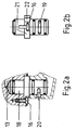
- Kupplungspartie zu den Schwenkausläufen, wobei Fig. 2a im Seitenriss und Fig. 2b als Ansicht von hinten gezeichnet ist.
- In Figur 1 enthält die Einpunktarmatur, unter anderem das Bedienungsorgan 1, die Ummantelung 2, den vorzugsweise einstückig ausgebildeten Innenkörper 3, die Ueberwurfmutter 4 und ein in einer ringförmigen Nut 5a des Innenkörpers 3 sitzenden Sprengring 5, der durch den Sicherungsring 6 gesichert ist. Die Ueberwurfmutter sitzt mit einem ungefähr ihrer Länge entsprechenden Achsialspiel z auf einer Schulter des Innenkörpers 3 und verbindet die Einpunktarmatur über den Sprengring 5 und den Sicherungsring 6 und über Abdichtungen 25 in Drehrichtung kraftschlüssig sowie dicht mit dem Armaturenanschlussorgan 7. Durch diese Anordnung sind die Befestigungsmittel 4, 5, 6 schnell und leicht in Montagerichtung der Armatur gegen das Armaturenanschlussorgan 7 demontierbar.
- Das Armaturenanschlussorgan 7 besteht aus einem Gehäuse 26 und einem im Gehäuse 26 drehbar eingesetzten Einsatz 27 mit zwei Kanälen 28 für Kalt- und Warmwasser, welche mit entsprechenden Kanälen 29 des Innenkörpers 3 fluchten. Zur Drehsicherung greifen zwei am Einsatz 27 angeformte Zapfen 30 in entsprechende Bohrungen 31 des Innenkörpers 3 ein. Dadurch wird erreicht, dass das Gehäuse 26 in beliebiger Drehstellung in der Wand montiert werden kann. Ausserdem können durch Drehen des Einsatzes 27 Kalt- und Warmwasser-Anschluss vertauscht werden. Die kraftschlüssige Verbindung von Innenkörper 3 und Anschlussorgan 7 erleichtert daher die Installation der Zuleitungen.
- Die Rosette 8 trägt in ihrer Innenseite Mittel zur sprizwasserdichten Abdichtung gegen die Wand 23 einerseits und gegen die Ummantelung 2 der Einpunktarmatur andererseits, sowie eine Schraube 10. Diese Schraube 10 spreizt beim Eindrehen die Abdichtung 9a reibschlüssig gegen die Ummantelung 2 und dient somit als Fixierelement für die Rosette auf der Einpunktarmatur, um die Anpressungen der Dichtmittel unter der Rosette jahrelang zu erhalten.
- Die Art der Befestigung der Ueberwurfmutter 4 mittels Sprengring 5 und Sicherungsring 6 erlaubt einerseits eine im Durchmesser kleinere Bauweise des Armaturenkörpers 2 und 3 als diejenige der Ueberwurfmutter und andererseits die bereits erwähnte schnelle und leichte Montage der Ueberwurfmutter 4, nachdem die, als einstückige Baugruppe konzipierte Rosette bei loser Schraube 10 auf die Ummantelung 2 aufgeschoben worden ist. Um eine leichte Montage der Ueberwurfmutter 4 mit dem in oder auf der Wand befestigten Armaturenanschlussorgan 7 zu gewährleisten, ist es günstig, dass die Rosette möglichst weit auf der Ummantelung 2 in Richtung des Bedienungsorgans 1 geschoben werden kann. Hierdurch wird der nötige Platz für den passenden Montageschlüssel zwecks Werkzeug-Angriff in Längsnuten 32 der Ueberwurfmutter 4 in Innern der Wand geschaffen.
- Wird dieser Montagevorgang vor der Montage der Kupplungspartie für den Auslauf 14 ausgeführt, so kann die Rosette 8 beim Anschlussvorgang an das Armaturenanschlussorgan 7 bei passend ausgebildeter Geometrie der Einpunktarmatur ungefähr bis zum Bedienungsorgan 1 hin auf den Armaturenkopf vorgeschoben werden, was sich als besonders vorteilhaft zeigt.
- Der Innenkörper 3 enthält die Zuleitungen 29 für Warm- und Kaltwasser vom Armaturenanschlussorgan 7 zum die Absperr- und Mischeinrichtung enthaltenden Mischorgan 11, welches mittels einem Nocken 12 mit dem Innenkörper 3 drehfest verbunden ist, sowie den Mischwasserabgang 13, der zur Kupplungspartie Fig. 2 und sodann zum Auslauf 14 führt. Weiter trägt er die Ummantelung 2, welche über eine O-Ringbremse 15 von beiden Seiten her auf den Innenkörper 3 aufschiebbar ist. Die beidseitige Aufschiebbarkeit der Ummantelung hat den besonderen Vorteil, dass bei der Werksmontage der Innenkörper bereits mit vormontiertem Armaturenkopf (Bedienungsorgan 1 und Mischorgan 11), und mit der Kopfummantelung 17a und 17b, jedoch ohne Anschlussteile (Ueberwurfmutter 4, Sprengring 5 und Sicherungsring 6), ohne Ummantelung 2, ohne Rosette und ohne Kupplungspartie gemäss Fig 2 auf Funktion und Dichtheit geprüft werden kann. Hierdurch sind allfällige Undichtheiten am Innenkörper sofort sichtbar.
- Andererseits kann im druckbeaufschlagten, geschlossenen Betriebszustand der Armatur unter Demontage des Bedienungsorgans 1, der Kopfummantelung 17a und 17b, sowie der Kupplungspartie gemäss Fig. 2 sowohl die Ummantelung 2 wie auch die einstückig ausgebildete Rosette 8 problemlos nach vorne demontiert werden, um Wartungen durchzuführen. Hierbei braucht das Wasser nicht abgestellt und/oder die Einpunktarmatur vom Anschlussorgan 7 demontiert zu werden.
- Die Ummantelung 2 ist auf dem Innenkörper mittels der Schraube 16 dreh- und rutschfest gehalten.Dies wiederum ist für die dauerhafte Anpressung der Dichtmittel 9 unter der Rosette 8 und zur Erhaltung der Drehbarkeit des Armaturenkopfes 1,17,17a, bei Bedienung der Armatur unbedingt erforderlich. Der Schraubenkopf der Schraube 16 stellt diese Halterung infolge der Höhe H seines Schraubenkopfs bereits im nur teilweise eingedrehten Zustande her, was die Vorteile der nachfolgenden Erläuterungen bewirkt:
- In Fig. 2 ist die Kupplungspartie zum Auslauf 14, 14a, 14b nochmals gezeichnet. Die Schraube 16 dient zusätzlich zur Halterung und Verdrehsicherung des Drehlagerelements 18. Die leichte Auswechselbarkeit und Kombinierbarkeit von Ausläufen verschiedener Längen und Ausführungen 14, 14a mit dem stets gleichen Einpunktarmaturenkörper sind bekannt. Die Kupplung und Lagerung der Schwenkausläufe erfolgt in der Regel meist an einem Zapfen ähnlich dem Drehlagerelement 18 mittels Fixierschrauben 20. Die Drehlagerelemente sind jedoch meistens im Armaturenkörper verdrehfest eingeschraubt oder eingelötet. Bei der erfindungsgemässen Ausbildung der Einpunktarmatur erfolgt diese Kupplung jedoch über das leicht demontierbare Drehlagerelement 18.
Dieses Drehlagerelement 18 enthält einerseits eine Nut 19, die zur Schwenkwinkelbegrenzung des Auslaufes 14 dient, und ragt als Zapfen in diesen Auslauf 14 hinein. Der Schwenkauslauf 14 selbst ist mittels einer Fixierschraube 20 auf diesem Zapfen befestigt und bildet so zusammen mit dem Drehlagerelement 18 eine vormontierte, prüfbare Baueinheit, welche mit O-Ringen in geeigneter Weise in sich und gegen den Innenkörper 3 abgedichtet ist. - Um eine vorteilhafte Schnellmontage zu gewährleisten, trägt das Drehlagerelement 18 andererseits einen Bund 21, der als Tiefenanschlag dient, und welcher bajonettverschlussartige Vertiefungen 22 aufweist.
- Hierdurch ist die vorstehende, vormontierte Auslauf-Baueinheit der Einpunktarmatur, bestehend aus Drehlagerelement 18 und Schwenkauslauf 14, bei noch nicht ganz eingedrehter Schraube 16 schnell und leicht durch geeignete Drehbewegung, den bajonettverschlussartigen Vertiefungen folgend, in den Innenkörper 3 einführbar. Sie wird sodann durch Eindrehen der Schraube 16 auf Tiefenanschlag gegen Herausfallen und gegen Verdrehen im Innenkörper 3 gesichert. Hierdurch ist die Doppelfunktion der Schraube 16 (Fixierung der Ummantelung 2 einerseits und verdrehsichere Halterung des Drehlagerelements 18 andererseits) erreicht.
- Zwischen der Ummantelung 2 und dem Innenkörper 3 entsteht bei der gezeichneten Ausführungsform ein relativ grosser Luftraum 24. Dies bewirkt den Vorteil einer Leichtbauweise der Einpunktarmatur und der Temperaturisolierung gegen die Ummantelung 3. Auch wenn der Innenkörper infolge Heisswasserzapfung sich erwärmt, ist Verbrennungsgefahr beim Berühren der Einpunktarmatur an der Ummantelung 3 ausgeschlossen.
Claims (9)
- Einpunktarmatur zur Montage auf einem in oder auf der Gebäudewand angeordneten Armaturenanschlussorgan (7), mit einer Abdeckrosette (8) und mit mindestens einem Mischorgan (11), welches durch mindestens ein Bedienungsorgan (1) betätigbar ist, dadurch gekennzeichnet, dass ein Innenkörper (3), welcher Kanäle (29) für Kalt- und Warmwasser aufweist, eine Ummantelung (2) aufweist und mindestens abflusseitig mit einer Schnellkupplung ausgerüstet ist.
- Einpunktarmatur gemäss Oberbegriff des Anspruchs 1, mit Befestigungsmitteln zur Verbindung mit dem Armaturenanschlussorgan (7), dadurch gekennzeichnet, dass die Befestigungsmittel zur kraftschlüssigen Verbindung mit dem Anschlussorgan (7) in Drehrichtung ausgebildet sind, und dass die Befestigungsmittel in Montagerichtung der Einpunktarmatur gegen das Armaturenanschlussorgan hin demontierbar sind.
- Einpunktarmatur nach Anspruch 2, dadurch gekennzeichnet, dass die Befestigungsmittel als Ueberwurfmutter (4) mit achsialem Spiel (z) und Sprengring (5) mit Sicherungsring (6) ausgebildet sind.
- Einpunktarmatur nach Anspruch 3, dadurch gekennzeichnet, dass die Befestigungsmittel einen Durchmesser aufweisen, welcher grösser als die Armaturenummantelung ist.
- Einpunktarmatur gemäss einem der Ansprüche 1 bis 4, dadurch gekennzeichnet, dass die Ummantelung (2) auf dem vorzugsweise einstückig ausgebildeten Innenkörper (1) mittels einem von aussen bedienbaren Befestigungselement (16) fixiert ist.
- Einpunktarmatur nach Anspruch 5, dadurch gekennzeichnet, dass das Befestigungselement (16) gleichzeitig Halterung und Fixierung für ein Drehlagerelement (18) eines Auslaufs (14) ist.
- Einpunktarmatur nach Anspruch 6, dadurch gekennzeichnet, dass das Drehlagerelement (18) mit dem Auslauf (14) eine vormontierte Baueinheit bildet.
- Einpunktarmatur nach einem der Ansprüche 1 bis 7, dadurch gekennzeichnet, dass die Ummantelung (3) auf dem Innenkörper (2) in beiden Achsrichtungen montierbar und demontierbar ist.
- Einpunktarmatur nach einem der Ansprüche 1 bis 8, dadurch gekennzeichnet, dass zwischen der Ummantelung (2) und dem Innenkörper (3) ein Luftraum (24) vorhanden ist.
Applications Claiming Priority (2)
| Application Number | Priority Date | Filing Date | Title |
|---|---|---|---|
| CH115894 | 1994-04-18 | ||
| CH1158/94 | 1994-04-18 |
Publications (3)
| Publication Number | Publication Date |
|---|---|
| EP0678630A2 true EP0678630A2 (de) | 1995-10-25 |
| EP0678630A3 EP0678630A3 (de) | 1996-02-14 |
| EP0678630B1 EP0678630B1 (de) | 1998-05-27 |
Family
ID=4203839
Family Applications (1)
| Application Number | Title | Priority Date | Filing Date |
|---|---|---|---|
| EP95810253A Expired - Lifetime EP0678630B1 (de) | 1994-04-18 | 1995-04-13 | Einpunktarmatur |
Country Status (4)
| Country | Link |
|---|---|
| US (1) | US5647393A (de) |
| EP (1) | EP0678630B1 (de) |
| AT (1) | ATE166683T1 (de) |
| DE (1) | DE59502305D1 (de) |
Families Citing this family (2)
| Publication number | Priority date | Publication date | Assignee | Title |
|---|---|---|---|---|
| ATE434091T1 (de) * | 2005-01-27 | 2009-07-15 | Kwc Ag | Sanitärarmatur mit schwenkbarem wasserauslass |
| US20070251590A1 (en) * | 2006-05-01 | 2007-11-01 | Hal Weinstein | Dual articulated faucet for lavatory bowls |
Citations (2)
| Publication number | Priority date | Publication date | Assignee | Title |
|---|---|---|---|---|
| CH673689A5 (de) | 1986-08-22 | 1990-03-30 | Wallisellen Ag Armaturen | |
| EP0392176A1 (de) | 1989-03-09 | 1990-10-17 | Friedrich Grohe Aktiengesellschaft | Anschlussvorrichtung für Wasserarmaturen |
Family Cites Families (12)
| Publication number | Priority date | Publication date | Assignee | Title |
|---|---|---|---|---|
| GB931705A (en) * | 1961-04-14 | 1963-07-17 | Barking Brassware | Improvements in or relating to fluid mixing devices |
| GB1216121A (en) * | 1968-02-28 | 1970-12-16 | Imi Dev Ltd | Improvements in or relating to mixer taps |
| DE1784504B2 (de) * | 1968-08-14 | 1975-10-16 | Friedrich Grohe Armaturenfabrik, 5870 Hemer | Mischbatterie |
| DE2412679A1 (de) * | 1973-03-26 | 1974-10-10 | Walter Hussauf | Wandanschluss fuer wasserarmatur |
| US4026328A (en) * | 1975-07-28 | 1977-05-31 | Zin-Plas Corporation | Lavatory spout |
| US4037624A (en) * | 1976-03-01 | 1977-07-26 | Bristol Products, Inc. | Spout assembly |
| US4778108A (en) * | 1987-02-13 | 1988-10-18 | Richards Marvin D | Spigot water fountain |
| DE3717442A1 (de) * | 1987-05-23 | 1988-12-08 | Grohe Armaturen Friedrich | Mischbatterie |
| DE3723828A1 (de) * | 1987-07-18 | 1989-01-26 | Grohe Armaturen Friedrich | Anschlussvorrichtung fuer mischarmaturen und verfahren zum anschluss der armatur |
| DE3907588A1 (de) * | 1989-03-09 | 1990-09-13 | Grohe Armaturen Friedrich | Befestigungsvorrichtung |
| DE4113879C2 (de) * | 1990-05-10 | 1996-09-05 | Grohe Armaturen Friedrich | Einlochmischbatterie |
| DE4138938A1 (de) * | 1991-11-27 | 1993-06-03 | Grohe Armaturen Friedrich | Wasserarmatur mit schwenkbarem auslaufrohr |
-
1995
- 1995-04-13 EP EP95810253A patent/EP0678630B1/de not_active Expired - Lifetime
- 1995-04-13 AT AT95810253T patent/ATE166683T1/de active
- 1995-04-13 DE DE59502305T patent/DE59502305D1/de not_active Expired - Lifetime
-
1996
- 1996-08-19 US US08/699,197 patent/US5647393A/en not_active Expired - Lifetime
Patent Citations (2)
| Publication number | Priority date | Publication date | Assignee | Title |
|---|---|---|---|---|
| CH673689A5 (de) | 1986-08-22 | 1990-03-30 | Wallisellen Ag Armaturen | |
| EP0392176A1 (de) | 1989-03-09 | 1990-10-17 | Friedrich Grohe Aktiengesellschaft | Anschlussvorrichtung für Wasserarmaturen |
Also Published As
| Publication number | Publication date |
|---|---|
| US5647393A (en) | 1997-07-15 |
| DE59502305D1 (de) | 1998-07-02 |
| ATE166683T1 (de) | 1998-06-15 |
| EP0678630B1 (de) | 1998-05-27 |
| EP0678630A3 (de) | 1996-02-14 |
Similar Documents
| Publication | Publication Date | Title |
|---|---|---|
| EP1261824B1 (de) | Sanitärarmatur | |
| EP0386594B1 (de) | Sanitäres Wasserauslaufventil | |
| EP2313207B1 (de) | Kopf- oder seitenbrause | |
| EP0386595B1 (de) | Mischbatterie | |
| DE102008023671B4 (de) | Wandhalterung | |
| DE19529189C2 (de) | Anschlußstück | |
| WO2005068884A1 (de) | Sanitärarmatur | |
| EP0678630A2 (de) | Einpunktarmatur | |
| EP0701028B1 (de) | Sanitäre Armatur | |
| DE10153988B4 (de) | Sollwerteinstellvorrichtung an einem thermostatisch geregelten Mischventil | |
| DE4105387C1 (de) | ||
| DE19902397C1 (de) | Sanitärarmatur, insbesondere Waschtischarmatur | |
| DE9101627U1 (de) | Über-Kopf-gesteuerte Einloch-Einhebelmischbatterie | |
| EP1837578B1 (de) | Anschlussstutzen zum drehbaren Anschluss eines Sanitärschlauchs | |
| DE102004037051B4 (de) | Mischbatterie mit Standanschluss | |
| DE19501313A1 (de) | Seitenbrause | |
| EP0716255B1 (de) | Sanitärarmatur | |
| EP0780523B1 (de) | Mischarmatur mit schräg eingesetzen Zulaufrohren | |
| DE19913214A1 (de) | Ventilkartuschenanordnung | |
| EP1128108B1 (de) | Sanitäranschlusseinrichtung | |
| DE10358771B4 (de) | Ventil mit einem Betätigungsgriff | |
| DE1629877C (de) | Sicherheitsgasanschlußhahn für Steckeranschluß | |
| EP4159937A1 (de) | Vorrichtung zur befestigung einer sanitärarmatur | |
| DE2418832C3 (de) | Vorrichtung zum Anschließen von Sanitärarmaturen | |
| DE102006060930B4 (de) | Sanitärarmatur |
Legal Events
| Date | Code | Title | Description |
|---|---|---|---|
| PUAI | Public reference made under article 153(3) epc to a published international application that has entered the european phase |
Free format text: ORIGINAL CODE: 0009012 |
|
| AK | Designated contracting states |
Kind code of ref document: A2 Designated state(s): AT CH DE FR GB LI SE |
|
| PUAL | Search report despatched |
Free format text: ORIGINAL CODE: 0009013 |
|
| AK | Designated contracting states |
Kind code of ref document: A3 Designated state(s): AT CH DE FR GB LI SE |
|
| 17P | Request for examination filed |
Effective date: 19960415 |
|
| 17Q | First examination report despatched |
Effective date: 19960918 |
|
| GRAG | Despatch of communication of intention to grant |
Free format text: ORIGINAL CODE: EPIDOS AGRA |
|
| GRAG | Despatch of communication of intention to grant |
Free format text: ORIGINAL CODE: EPIDOS AGRA |
|
| GRAH | Despatch of communication of intention to grant a patent |
Free format text: ORIGINAL CODE: EPIDOS IGRA |
|
| GRAH | Despatch of communication of intention to grant a patent |
Free format text: ORIGINAL CODE: EPIDOS IGRA |
|
| GRAA | (expected) grant |
Free format text: ORIGINAL CODE: 0009210 |
|
| AK | Designated contracting states |
Kind code of ref document: B1 Designated state(s): AT CH DE FR GB LI SE |
|
| PG25 | Lapsed in a contracting state [announced via postgrant information from national office to epo] |
Ref country code: GB Free format text: LAPSE BECAUSE OF FAILURE TO SUBMIT A TRANSLATION OF THE DESCRIPTION OR TO PAY THE FEE WITHIN THE PRESCRIBED TIME-LIMIT Effective date: 19980527 Ref country code: FR Free format text: LAPSE BECAUSE OF FAILURE TO SUBMIT A TRANSLATION OF THE DESCRIPTION OR TO PAY THE FEE WITHIN THE PRESCRIBED TIME-LIMIT Effective date: 19980527 |
|
| REF | Corresponds to: |
Ref document number: 166683 Country of ref document: AT Date of ref document: 19980615 Kind code of ref document: T |
|
| REG | Reference to a national code |
Ref country code: CH Ref legal event code: NV Representative=s name: ISLER & PEDRAZZINI AG Ref country code: CH Ref legal event code: EP |
|
| REF | Corresponds to: |
Ref document number: 59502305 Country of ref document: DE Date of ref document: 19980702 |
|
| PG25 | Lapsed in a contracting state [announced via postgrant information from national office to epo] |
Ref country code: SE Free format text: LAPSE BECAUSE OF FAILURE TO SUBMIT A TRANSLATION OF THE DESCRIPTION OR TO PAY THE FEE WITHIN THE PRESCRIBED TIME-LIMIT Effective date: 19980827 |
|
| EN | Fr: translation not filed | ||
| GBV | Gb: ep patent (uk) treated as always having been void in accordance with gb section 77(7)/1977 [no translation filed] |
Effective date: 19980527 |
|
| PLBE | No opposition filed within time limit |
Free format text: ORIGINAL CODE: 0009261 |
|
| STAA | Information on the status of an ep patent application or granted ep patent |
Free format text: STATUS: NO OPPOSITION FILED WITHIN TIME LIMIT |
|
| 26N | No opposition filed | ||
| REG | Reference to a national code |
Ref country code: CH Ref legal event code: PCAR Free format text: ISLER & PEDRAZZINI AG;POSTFACH 1772;8027 ZUERICH (CH) |
|
| REG | Reference to a national code |
Ref country code: CH Ref legal event code: PUE Owner name: ARWA AG Free format text: ARMATURENFABRIK WALLISELLEN AG#RICHTISTRASSE 2#CH-8304 WALLISELLEN (CH) -TRANSFER TO- ARWA AG#RICHTISTRASSE 2#8304 WALLISELLEN (CH) |
|
| REG | Reference to a national code |
Ref country code: CH Ref legal event code: NV Representative=s name: BOHEST AG, CH |
|
| REG | Reference to a national code |
Ref country code: CH Ref legal event code: PCAR Free format text: NEW ADDRESS: HOLBEINSTRASSE 36-38, 4051 BASEL (CH) |
|
| PGFP | Annual fee paid to national office [announced via postgrant information from national office to epo] |
Ref country code: DE Payment date: 20140630 Year of fee payment: 20 Ref country code: CH Payment date: 20140424 Year of fee payment: 20 Ref country code: AT Payment date: 20140425 Year of fee payment: 20 |
|
| REG | Reference to a national code |
Ref country code: DE Ref legal event code: R071 Ref document number: 59502305 Country of ref document: DE |
|
| REG | Reference to a national code |
Ref country code: CH Ref legal event code: PL |
|
| REG | Reference to a national code |
Ref country code: AT Ref legal event code: MK07 Ref document number: 166683 Country of ref document: AT Kind code of ref document: T Effective date: 20150413 |