EP0678631A2 - Steuervorrichtung für Vakuumventil für Unterdruckabwasseranlage - Google Patents
Steuervorrichtung für Vakuumventil für Unterdruckabwasseranlage Download PDFInfo
- Publication number
- EP0678631A2 EP0678631A2 EP95104657A EP95104657A EP0678631A2 EP 0678631 A2 EP0678631 A2 EP 0678631A2 EP 95104657 A EP95104657 A EP 95104657A EP 95104657 A EP95104657 A EP 95104657A EP 0678631 A2 EP0678631 A2 EP 0678631A2
- Authority
- EP
- European Patent Office
- Prior art keywords
- vacuum valve
- vacuum
- suction pipe
- soil water
- pressure
- Prior art date
- Legal status (The legal status is an assumption and is not a legal conclusion. Google has not performed a legal analysis and makes no representation as to the accuracy of the status listed.)
- Ceased
Links
Images



Classifications
-
- E—FIXED CONSTRUCTIONS
- E03—WATER SUPPLY; SEWERAGE
- E03F—SEWERS; CESSPOOLS
- E03F1/00—Methods, systems, or installations for draining-off sewage or storm water
- E03F1/006—Pneumatic sewage disposal systems; accessories specially adapted therefore
-
- F—MECHANICAL ENGINEERING; LIGHTING; HEATING; WEAPONS; BLASTING
- F16—ENGINEERING ELEMENTS AND UNITS; GENERAL MEASURES FOR PRODUCING AND MAINTAINING EFFECTIVE FUNCTIONING OF MACHINES OR INSTALLATIONS; THERMAL INSULATION IN GENERAL
- F16K—VALVES; TAPS; COCKS; ACTUATING-FLOATS; DEVICES FOR VENTING OR AERATING
- F16K51/00—Other details not peculiar to particular types of valves or cut-off apparatus
- F16K51/02—Other details not peculiar to particular types of valves or cut-off apparatus specially adapted for high-vacuum installations
-
- Y—GENERAL TAGGING OF NEW TECHNOLOGICAL DEVELOPMENTS; GENERAL TAGGING OF CROSS-SECTIONAL TECHNOLOGIES SPANNING OVER SEVERAL SECTIONS OF THE IPC; TECHNICAL SUBJECTS COVERED BY FORMER USPC CROSS-REFERENCE ART COLLECTIONS [XRACs] AND DIGESTS
- Y10—TECHNICAL SUBJECTS COVERED BY FORMER USPC
- Y10S—TECHNICAL SUBJECTS COVERED BY FORMER USPC CROSS-REFERENCE ART COLLECTIONS [XRACs] AND DIGESTS
- Y10S137/00—Fluid handling
- Y10S137/907—Vacuum-actuated valves
-
- Y—GENERAL TAGGING OF NEW TECHNOLOGICAL DEVELOPMENTS; GENERAL TAGGING OF CROSS-SECTIONAL TECHNOLOGIES SPANNING OVER SEVERAL SECTIONS OF THE IPC; TECHNICAL SUBJECTS COVERED BY FORMER USPC CROSS-REFERENCE ART COLLECTIONS [XRACs] AND DIGESTS
- Y10—TECHNICAL SUBJECTS COVERED BY FORMER USPC
- Y10T—TECHNICAL SUBJECTS COVERED BY FORMER US CLASSIFICATION
- Y10T137/00—Fluid handling
- Y10T137/2931—Diverse fluid containing pressure systems
- Y10T137/3109—Liquid filling by evacuating container
-
- Y—GENERAL TAGGING OF NEW TECHNOLOGICAL DEVELOPMENTS; GENERAL TAGGING OF CROSS-SECTIONAL TECHNOLOGIES SPANNING OVER SEVERAL SECTIONS OF THE IPC; TECHNICAL SUBJECTS COVERED BY FORMER USPC CROSS-REFERENCE ART COLLECTIONS [XRACs] AND DIGESTS
- Y10—TECHNICAL SUBJECTS COVERED BY FORMER USPC
- Y10T—TECHNICAL SUBJECTS COVERED BY FORMER US CLASSIFICATION
- Y10T137/00—Fluid handling
- Y10T137/402—Distribution systems involving geographic features
-
- Y—GENERAL TAGGING OF NEW TECHNOLOGICAL DEVELOPMENTS; GENERAL TAGGING OF CROSS-SECTIONAL TECHNOLOGIES SPANNING OVER SEVERAL SECTIONS OF THE IPC; TECHNICAL SUBJECTS COVERED BY FORMER USPC CROSS-REFERENCE ART COLLECTIONS [XRACs] AND DIGESTS
- Y10—TECHNICAL SUBJECTS COVERED BY FORMER USPC
- Y10T—TECHNICAL SUBJECTS COVERED BY FORMER US CLASSIFICATION
- Y10T137/00—Fluid handling
- Y10T137/7287—Liquid level responsive or maintaining systems
- Y10T137/7313—Control of outflow from tank
- Y10T137/7316—Self-emptying tanks
-
- Y—GENERAL TAGGING OF NEW TECHNOLOGICAL DEVELOPMENTS; GENERAL TAGGING OF CROSS-SECTIONAL TECHNOLOGIES SPANNING OVER SEVERAL SECTIONS OF THE IPC; TECHNICAL SUBJECTS COVERED BY FORMER USPC CROSS-REFERENCE ART COLLECTIONS [XRACs] AND DIGESTS
- Y10—TECHNICAL SUBJECTS COVERED BY FORMER USPC
- Y10T—TECHNICAL SUBJECTS COVERED BY FORMER US CLASSIFICATION
- Y10T137/00—Fluid handling
- Y10T137/7287—Liquid level responsive or maintaining systems
- Y10T137/7339—By weight of accumulated fluid
Definitions
- the present invention relates to a vacuum valve controller for a vacuum sewer system in which soil water in a soil water basin is sucked through a suction pipe by opening a vacuum valve and sent to a predetermined place, e.g., a sewage disposal plant.
- FIG. 5 shows one example of the arrangement of a conventional vacuum sewer system of the type described above.
- reference numeral 10 denotes a soil water basin.
- One end of a suction pipe 12 is inserted into the soil water basin 10.
- the other, or rear, end of the suction pipe 12 is connected to a line 15 which communicates with a vacuum tank (vacuum system not shown) through a main valve 14 of a vacuum valve.
- a vacuum valve body 13 has in a chamber 13c a diaphragm 13b and a spring 13a for biasing the diaphragm 13b into a valve closing position.
- Reference numeral 200 denotes a controller for on/off controlling the vacuum valve.
- the controller 200 has a cylindrical casing 201.
- the inside of the casing 201 is divided into a sensor chamber 202, a first chamber 203, a second chamber 204, a third chamber 205, a fourth chamber 206, and a fifth chamber 207.
- the sensor chamber 202 is connected to a pressure sensor pipe 11, which is disposed in the soil water basin 10 through a pipe 208.
- the fifth chamber 207 is connected to an actuating chamber 13c in the vacuum valve body 13 through a pipe 209. Further, the fifth chamber 207 communicates with the outside air through a breather pipe 210.
- the fourth chamber 206 is connected to the line 15 through a pipe 211 and a check valve 212.
- the first chamber 203 is connected to the breather pipe 210 through a filter 213 and a check valve 214 with an orifice.
- the second and third chambers 204 and 205 are connected to each other by a pipe 216 through a needle valve 215.
- the distal end of the pipe 216 is connected to the fourth chamber 206 through a bevel check valve 217.
- a three-way valve 222 is held in the leftward position by the biasing force of a spring 221. Since the fifth chamber 207 communicates with the atmospheric air through the breather pipe 210, the chamber 13c in the vacuum valve body 13 is placed under the atmospheric pressure. Accordingly, the main valve 14 is pressed in the direction for closing the valve by the spring 13a and thus set in a full-closed state.
- the pressure detected by the pressure sensor pipe 11 rises. Consequently, the sensor diaphragm 218 moves rightward and comes in contact with the sensor lever 220.
- the pressure exceeds a water column of about 20 mmAq, it overcomes the sum of the force of the spring 219 and the vacuum in the second chamber 204 and causes the sensor lever 220 to separate from the air passage 223.
- the air in the first chamber 203 flows into the second chamber 204 through the air passage 223, causing the pressure in the second chamber 204 to rise to a level higher than the pressure in the third chamber 205.
- a three-way valve driving diaphragm 222a moves rightward, causing the three-way valve 222 to close a hole which communicates with the breather pipe 210.
- the vacuum in the line 15 is coupled to the chamber 13c in the vacuum valve body 13 through the fourth chamber 206, the axial passage in the three-way valve 222, the fifth chamber 207 and the pipe 209.
- the vacuum in the chamber 13c overcomes the force of the spring 13a and raises the main valve 14 from its valve seat, thereby setting the vacuum valve in a fully-open state (i.e., a state where the bore that provides communication between the suction pipe 12 and the line 15 is open).
- the controller 200 arranged as described above, however, suffers from the following problems:
- the breather pipe 210 must be installed outdoors in order to prevent water or any other liquid from entering the casing of the controller 200.
- the present invention provides a vacuum valve controller for a vacuum sewer system having a suction pipe which is communicated with a vacuum system by opening a vacuum valve, and which is cut off from the vacuum system by closing the vacuum valve, so that soil water in a soil water basin is sucked through the suction pipe and sent to a predetermined place by opening the vacuum valve.
- the vacuum valve controller is characterized by comprising a device for detecting a soil water level when the suction pipe begins to suck air from a lower end thereof when the soil water level has fallen as a result of suction of soil water through the suction pipe, and a control device for closing the vacuum valve when the detecting device detects that the suction pipe has begun to suck air through the suction pipe.
- the vacuum valve controller is further characterized in that the detection device detects that the suction pipe begins to suck air from a change of pressure difference between two points in the suction pipe which are different in height from each other.
- the vacuum valve controller is characterized in that the controller includes a pressure sensor pipe for converting the rising of the soil water within the soil water basin into a pressure and transmitting the pressure to the control device, and the control device opens the vacuum valve by means of the pressure when the soil water level within the soil water basin reaches a predetermined value.
- the vacuum valve controller is also characterized in that the pressure difference between the two points in the suction pipe is transmitted to the control device and the control device holds the vacuum valve being open by means of the pressure difference applied thereto.
- the vacuum valve controller is further characterized in that the controller includes a vacuum valve on/off control mechanism for opening and closing the vacuum valve, the vacuum valve on/off control mechanism includes a shaft reciprocably provided within a casing and a valve body provided on the shaft, the valve body is shiftable between a first position where an actuating chamber of the vacuum valve is communicated with a line of the vacuum system for opening the vacuum valve and a second position where the actuating chamber is opened to atmospheric air for closing the vacuum valve.
- the vacuum valve controller is characterized in that the control device comprises a vacuum valve on/off control mechanism for opening and closing the vacuum valve, a reciprocating shaft for operating the vacuum valve on/off control mechanism, first and second diaphragms attached to the shaft, a spring means for biasing the shaft in the normal direction for closing the vacuum valve, a pair of pressurized chambers for applying pressure on both sides of the first diaphragm, a pressurized chamber for applying a pressure on one side of the second diaphragm to thereby shift the shaft in a direction for opening the vacuum valve, and a pressure sensor pipe for converting the rise of the soil water level in the soil water basin into a pressure.
- the control device comprises a vacuum valve on/off control mechanism for opening and closing the vacuum valve, a reciprocating shaft for operating the vacuum valve on/off control mechanism, first and second diaphragms attached to the shaft, a spring means for biasing the shaft in the normal direction for closing the vacuum valve, a pair of pressurized chambers for applying pressure on both sides
- a soil water pressure at two points different in height of the suction pipe is transmitted to the pressurized chambers on both sides of the first diaphragm so that a pressure difference therebetween operates to shift the shaft in a direction for opening the valve against the spring means, and a pressure generated in the pressure sensor pipe is transmitted to the pressurized chamber on one side of the second diaphragm.
- the vacuum valve controller is characterized in that fluid restrictions are provided in respective pipes connecting the control device and the suction pipe for transmitting the soil water pressure to the pressurized chambers on both sides of the first diaphragm, whereby reciprocating of the shaft within a short period due to temporal fluctuation of the pressure difference between the two different points in the suction pipe is prevented and the movement of the first diaphragm is delayed to control the volume of suction air through the vacuum valve.
- the vacuum valve controller is further characterized in that a magnet is provided for attracting the shaft in a direction in which the vacuum valve is closed.
- the vacuum valve is closed after detecting that the suction pipe begins to suck air. Accordingly, the present invention is free from the problem that the amount of air sucked varies according to the degree of vacuum. Also, the present invention is free from the problems associated with the conventional controller that air lock occurs in the piping, since air is positively sucked in the suction pipe even if the degree of vacuum is low.
- the pressure difference between two points in the suction pipe which are different in height from each other is large during the suction of soil water, but it is small during the suction of air. Accordingly, it is possible to detect the fact that the suction pipe begins to suck air, from a point at which the pressure difference rapidly decreases.
- fluid restrictions are provided in respective pipes for transmitting a soil water pressure in the suction pipe to the pressurized chambers on both sides of the first diaphragm to prevent movement of the shaft within a short period due to the temporal fluctuation of the pressure difference between the two points in the suction pipe which are different in height and also delay the movement of the first diaphragm thereby controlling the volume of the suction air into the suction pipe.
- it is possible to prevent the opening and closing of the vacuum valve due to the temporal fluctuation of the pressure difference between two points in the suction pipe which are different in height and control the volume of the suction air through the vacuum valve.
- the present invention is characterized in that a second diaphragm is provided on the shaft, a sensor pipe is provided for converting the rise of soil water level within a soil water basin into a pressure, a pressurized chamber is provided for applying a pressure on one side of the second diaphragm to shift the shaft in the direction for opening the vacuum valve, and a pressure generated in the sensor pipe is transmitted to the pressurized chamber.
- a magnet is provided for attracting the shaft in a direction for closing the vacuum valve.
- Fig. 1 shows the arrangement of a vacuum sewer system which employs the vacuum valve controller of the present invention
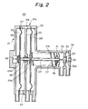
- Fig. 2 shows the detailed arrangement of the vacuum valve controller.
- portions which are denoted by the same reference numerals as those in Fig. 5 are the same or corresponding portions.
- reference numeral 18 denotes a simultaneous air suction pipe arranged to suck air simultaneously with the suction of soil water through the suction pipe 12.
- a controller 20 has a casing 21.
- the casing 21 has an integral structure composed of a large-diameter portion 21 a and a small-diameter portion 21 b.
- the large-diameter portion 21 a has a partition 22 in the center thereof to divide the inside of the large-diameter portion 21 a into left- and right-hand chambers.
- the partition 22 is pierced with a shaft 24 of a valve body 23.
- the left-hand chamber is divided into first and second chambers 26 and 27 by a second diaphragm 25 which is provided in the center thereof.
- the right-hand chamber is divided into third and fourth chambers 29 and 30 by a first diaphragm 28 which is provided in the center thereof.
- the inside of the small-diameter portion 21 b is divided into left- and right-hand chambers by a partition 31.
- the left-hand chamber communicates with the fourth chamber 30.
- the right-hand chamber is divided into fifth and sixth chambers 33 and 34 by a partition 32.
- the rear end of the shaft 24 is secured to the center of the second diaphragm 25 by means of a set screw 24a.
- the shaft 24 penetrates through the partition 22 and extends through the first diaphragm 28 (it should be noted that the first diaphragm 28 is secured to the shaft 24 by means of a set screw 24b).
- the shaft 24 further penetrates through the partitions 31 and 32.
- the portion of the partition 22 through which the shaft 24 penetrates is provided with a seal mechanism 35.
- the portion of the partition 31 through which the shaft 24 penetrates is provided with a seal mechanism 36.
- the portion of the partition 32 through which the shaft 24 penetrates is provided with a through-hole 32a which is opened or closed by the valve body 23.
- Reference numeral 37 denotes a spring that presses the first diaphragm 28 leftward.
- a magnet 38 is provided at a position on the rear end wall of the casing 21 which faces the rear end of the shaft 24, i.e., the set screw 24a made of a magnetic material.
- the sixth chamber 34 is provided with a hole 39 which is opened or closed by the valve body 23 and which communicates with the atmospheric air.
- the suction pipe 12 is provided with pressure detecting holes 16 and 17 with a predetermined spacing provided therebetween in the vertical direction.
- the pressure detecting hole 16 communicates with the fourth chamber 30 through a pipe 41.
- the pressure detecting hole 17 communicates with the third chamber 29 through a pipe 40.
- the pressure sensor pipe 11 communicates with the first chamber 26 through a pipe 42.
- the second chamber 27 communicates with the atmospheric air through a hole 43.
- the fifth chamber 33 communicates with the line 15 through a pipe 44.
- the sixth chamber 34 communicates with the chamber 13c in the vacuum valve body 13.
- the fifth chamber 33, the sixth chamber 34 and the valve body 23 constitute a vacuum valve on/off control mechanism for opening and closing the vacuum valve 13.
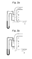
- Figs. 3(a) and 3(b) show the way in which the pressure difference between the pressure detecting holes 16 and 17 of the suction pipe 12, which are different in height from each other, changes.
- Fig. 3-(a) shows the pressure difference during the suction of soil water.
- Fig. 3(b) shows the pressure difference during the suction of air.
- the pressure difference is large, i.e., 0:1 x h; while during the suction of air, the pressure difference is exceedingly small, i.e., a 2 x h.
- the symbol h represents the dimension between the pressure detecting holes 16 and 17, 0:1 the specific weight of the soil water and a 2 the specific weight of air.
- the pressure difference is applied between the third and fourth chambers 29 and 30 as follows: During the suction of soil water, the diaphragm 28 is pushed rightward with the differential pressure of 0:1 x h; while during the suction of air, the pressure difference between the third and fourth chambers 29 and 30 is substantially zero. Thus, by detecting a point at which the pressure difference has become exceedingly small, it is possible to find that the level of soil water Q has reached the lower end of the suction pipe 12, that is, the level at which air begins to be sucked.
- fluid restrictions 40a and 41a are respectively provided in the pipe 40 connecting the pressure detecting hole 17 and the third chamber 29 and the pipe 41 connecting the pressure detecting hole 16 and the fourth chamber 30.
- These fluid restrictions 40a and 41 a prevent reciprocation of the shaft 24 in a short period due to the temporal fluctuation of the pressure difference between the pressure detecting holes 17 and 16 and delay the movement of the first diaphragm 28, thereby providing a function to control the volume of suction air through the vacuum valve.
- the vacuum valve 13 does not open or close in response to the temporal fluctuation of the pressure difference between the pressure detecting holes 17 and 16 which stabilizes the operation of the vacuum valve.
- Fig. 4 shows the relationship between the force applied to the shaft of the controller and the operational timing of the controller, wherein the abscissa denotes the timing of the controller and the ordinate denotes the force applied to the shaft.
- a solid line E denotes the force acting to shift the shaft 24 rightward (vacuum valve opening direction) and the dot line F denotes the force (sum of the biasing force of the spring 37 and the magnetic attracting force of the magnet 38) acting to shift the shaft 24 leftward (vacuum valve closing direction).
- G denotes the set value for actuating the controller 20
- H the pressure difference between the pressure detecting holes 17 and 16 during the suction of the soil water into the suction pipe 12, and I the friction force caused in the seal mechanisms 35 and 36.
- the pressure detected in the pressure sensor pipe 11 is transmitted to the first chamber 26 which pushes the second diaphragm 25 of the controller 20 rightward.
- the pressure transmitted to the first chamber overcomes the sum of the biasing force of the spring 37 and the magnetic attracting force of the magnet 38 and, consequently the shaft 24 is shifted rightward (vacuum valve opening direction) until the valve body 23 closes the hole 39.
- the relationship between the force E and the force F is E > F and, therefore, the controller is brought under the vacuum valve opening operation A.
- the controller 20 With the above-described arrangement of the controller 20, the fact that the level of soil water has fallen to such an extent that air begins to be sucked from the lower end of the suction pipe 12 is detected from the fact that there is no pressure difference between the pressure detecting holes 16 and 17, and the main valve 14 of the vacuum valve is closed to cut off the communication between the suction pipe 12 and the line 15. Accordingly, there is no possibility that the closing of the vacuum valve is extremely delayed. Also, there is no possibility that a large amount of air will be sucked through the suction pipe 12 at one gulp after soil water in the soil water basin 10 has been sucked. Therefore, there is not likelihood that the level of water used, for example, in a domestic flush toilet would fall to an undesirable level, thereby causing the trap to be destroyed.
- the controller 20 since no vacuum is used as force for activating the vacuum valve controller as in the conventional controller, the controller 20 is free from the above-described conventional problems arising from the use of a vacuum. Since the operation is independent of the degree of vacuum, a stable operation can be obtained.
- a soil water level at which the suction pipe 12 begins to suck air is detected from a change of the pressure difference between the pressure detecting holes 16 and 17 of the suction pipe 12 which are different in height from each other, it should be noted that the device for detecting the fact that air begins to be sucked is not necessarily limited to the described arrangement.
- the present invention provides the following advantageous effects:
Landscapes
- Engineering & Computer Science (AREA)
- Health & Medical Sciences (AREA)
- Life Sciences & Earth Sciences (AREA)
- Hydrology & Water Resources (AREA)
- Public Health (AREA)
- Water Supply & Treatment (AREA)
- General Engineering & Computer Science (AREA)
- Mechanical Engineering (AREA)
- Sewage (AREA)
Applications Claiming Priority (4)
| Application Number | Priority Date | Filing Date | Title |
|---|---|---|---|
| JP104587/94 | 1994-04-19 | ||
| JP10458794 | 1994-04-19 | ||
| JP07039362A JP3079411B2 (ja) | 1994-04-19 | 1995-02-02 | 真空式下水道システムの真空弁制御装置 |
| JP39362/95 | 1995-02-02 |
Publications (2)
| Publication Number | Publication Date |
|---|---|
| EP0678631A2 true EP0678631A2 (de) | 1995-10-25 |
| EP0678631A3 EP0678631A3 (de) | 1997-01-02 |
Family
ID=26378726
Family Applications (1)
| Application Number | Title | Priority Date | Filing Date |
|---|---|---|---|
| EP19950104657 Ceased EP0678631A3 (de) | 1994-04-19 | 1995-03-29 | Steuervorrichtung für Vakuumventil für Unterdruckabwasseranlage. |
Country Status (5)
| Country | Link |
|---|---|
| US (1) | US5588458A (de) |
| EP (1) | EP0678631A3 (de) |
| JP (1) | JP3079411B2 (de) |
| KR (1) | KR100401380B1 (de) |
| CN (1) | CN1065582C (de) |
Cited By (1)
| Publication number | Priority date | Publication date | Assignee | Title |
|---|---|---|---|---|
| EP0826838A3 (de) * | 1996-08-26 | 1998-03-11 | Ebara Corporation | Vakuumventilregler |
Families Citing this family (28)
| Publication number | Priority date | Publication date | Assignee | Title |
|---|---|---|---|---|
| DE19633178A1 (de) * | 1996-08-17 | 1998-02-19 | Roediger Anlagenbau | Steuerung für ein mit Unterdruck betätigbares Absaug- und/oder Wasserventil |
| DE29616003U1 (de) * | 1996-09-13 | 1997-02-13 | Roediger Vakuum- Und Haustechnik Gmbh, 63450 Hanau | Anordnung zum Absaugen von Flüssigkeit |
| JPH1143982A (ja) * | 1997-07-25 | 1999-02-16 | Sekisui Chem Co Ltd | 真空下水管の空気取入れ装置 |
| US6467497B1 (en) * | 1999-04-21 | 2002-10-22 | Evac International Oy | Buffer box for use in a vacuum drainage system |
| US6655402B1 (en) * | 2002-06-13 | 2003-12-02 | U.S. Environmental Protection Agency | System and method for vacuum flushing sewer solids |
| JP4105581B2 (ja) * | 2003-04-10 | 2008-06-25 | 株式会社荏原製作所 | 真空弁制御装置 |
| FI117298B (fi) * | 2005-01-25 | 2006-08-31 | Evac Int Oy | Alipaineviemärijärjestelmä |
| US7374669B2 (en) * | 2005-04-26 | 2008-05-20 | Acorn Engineering Co. | Vacuum waste removal system |
| US20090116969A1 (en) * | 2007-11-02 | 2009-05-07 | Mcvicker R Vance | Rail tank car evacuation and transfer system and method |
| CN102428235B (zh) * | 2009-04-03 | 2013-10-23 | 株式会社酉岛制作所 | 真空阀的控制装置 |
| US9828757B2 (en) * | 2010-01-27 | 2017-11-28 | Ip Sensing, Inc. | Distributed control system for a vacuum sewer system |
| US8228190B2 (en) * | 2010-02-24 | 2012-07-24 | Data Flow Systems, Inc. | Valve malfunctioning detection system for a vacuum sewer an associated methods |
| DE102010000609B4 (de) * | 2010-03-02 | 2015-03-12 | Roediger Vacuum Gmbh | Steueranordnung |
| JP5351808B2 (ja) * | 2010-03-19 | 2013-11-27 | 株式会社荏原製作所 | 真空弁の制御装置 |
| JP5351807B2 (ja) * | 2010-03-19 | 2013-11-27 | 株式会社荏原製作所 | 真空弁ユニット |
| CN102011430B (zh) * | 2010-09-25 | 2012-10-17 | 中国恩菲工程技术有限公司 | 从低位向高位输送液体的液体输送设备及污水提升系统 |
| US10001787B2 (en) | 2014-06-02 | 2018-06-19 | Aqseptence Group, Inc. | Controller for vacuum sewage system |
| US10745267B2 (en) * | 2015-12-21 | 2020-08-18 | Tetra Laval Holdings & Finance S.A. | Product loss reduction by using shortened purge for aseptic tank |
| FI127077B (en) * | 2016-04-19 | 2017-10-31 | Evac Oy | A method for controlling a vacuum system and a vacuum system |
| US10648382B2 (en) * | 2016-10-05 | 2020-05-12 | Parker-Hannifin Corporation | Inerting and venting system |
| US10584473B2 (en) | 2017-12-08 | 2020-03-10 | Legend Energy Advisors | Controlling a vacuum sewer system |
| CN108980446B (zh) * | 2018-08-31 | 2020-03-17 | 杭州电子科技大学 | 一种引线按钮压力切换装置 |
| CN109268552B (zh) * | 2018-08-31 | 2020-03-20 | 杭州电子科技大学 | 一种按压压力交换装置 |
| CN109056975A (zh) * | 2018-08-31 | 2018-12-21 | 杭州电子科技大学 | 一种地漏自控阀收集系统 |
| CN109269950A (zh) * | 2018-09-29 | 2019-01-25 | 上海峥兴环保科技有限公司 | 一种污泥指数自动监测系统 |
| US11299878B2 (en) * | 2019-03-21 | 2022-04-12 | Aqseptence Group, Inc. | Vacuum sewage system with sump breather apparatus |
| CN115183047B (zh) * | 2022-05-16 | 2026-01-06 | 苏州中鹿环保设备有限公司 | 具有延迟闭阀功能的启闭转换器 |
| CN116213379B (zh) * | 2023-03-21 | 2025-10-10 | 江苏徐工工程机械研究院有限公司 | 一种抽吸管路防堵和清洗系统、控制方法及抽吸车辆 |
Family Cites Families (12)
| Publication number | Priority date | Publication date | Assignee | Title |
|---|---|---|---|---|
| US3777778A (en) * | 1972-08-30 | 1973-12-11 | Johnson Service Co | Two-position liquid level controller |
| US3774637A (en) * | 1972-08-30 | 1973-11-27 | Johnson Service Co | Diaphragm actuated spool valve |
| US3998736A (en) * | 1976-05-12 | 1976-12-21 | Greenleaf Jr John W | Sewage disposal system |
| US4373838A (en) * | 1981-02-13 | 1983-02-15 | Burton Mechanical Contractors Inc. | Vacuum sewage transport system |
| US4373837A (en) * | 1981-05-28 | 1983-02-15 | T. Y. Lin International | Pier with prestressed resiliant integral deck to absorb docking forces of ships |
| GB2149534B (en) * | 1983-11-08 | 1986-12-10 | Cowells Sewerage Systems Limit | Liquid level control system |
| US4691731A (en) * | 1983-12-08 | 1987-09-08 | Burton Mechanical Contractors, Inc. | Vacuum sewerage system with in pit breather |
| SE449883B (sv) * | 1984-02-10 | 1987-05-25 | Waertsilae Oy Ab | Anordning vid ett vakuumtransportsystem for vetskor t ex vakuumavloppssystem |
| GB2215492B (en) * | 1988-02-04 | 1992-09-30 | Cowells Int Ltd | Liquid level control system |
| JPH0388621A (ja) * | 1989-08-31 | 1991-04-15 | Ebara Corp | 真空式汚水収集装置及び該装置用真空弁コントローラ |
| JPH062777A (ja) * | 1992-06-18 | 1994-01-11 | Sekisui Chem Co Ltd | 真空弁 |
| JP2652494B2 (ja) * | 1992-10-08 | 1997-09-10 | 株式会社イナックス | 真空式下水道システムにおける真空弁ユニット |
-
1995
- 1995-02-02 JP JP07039362A patent/JP3079411B2/ja not_active Expired - Lifetime
- 1995-03-29 KR KR1019950006829A patent/KR100401380B1/ko not_active Expired - Fee Related
- 1995-03-29 EP EP19950104657 patent/EP0678631A3/de not_active Ceased
- 1995-04-06 US US08/417,764 patent/US5588458A/en not_active Expired - Lifetime
- 1995-04-18 CN CN95105070A patent/CN1065582C/zh not_active Expired - Fee Related
Cited By (3)
| Publication number | Priority date | Publication date | Assignee | Title |
|---|---|---|---|---|
| EP0826838A3 (de) * | 1996-08-26 | 1998-03-11 | Ebara Corporation | Vakuumventilregler |
| US5871027A (en) * | 1996-08-26 | 1999-02-16 | Ebara Corporation | Vacuum valve controller |
| MY118911A (en) * | 1996-08-26 | 2005-02-28 | Ebara Corp | Vacuum valve controller |
Also Published As
| Publication number | Publication date |
|---|---|
| CN1123865A (zh) | 1996-06-05 |
| KR100401380B1 (ko) | 2004-02-25 |
| EP0678631A3 (de) | 1997-01-02 |
| KR950033213A (ko) | 1995-12-22 |
| CN1065582C (zh) | 2001-05-09 |
| JPH084093A (ja) | 1996-01-09 |
| JP3079411B2 (ja) | 2000-08-21 |
| US5588458A (en) | 1996-12-31 |
Similar Documents
| Publication | Publication Date | Title |
|---|---|---|
| US5588458A (en) | Vacuum valve controller for vacuum sewer system | |
| US5871027A (en) | Vacuum valve controller | |
| US4604194A (en) | Water conditioner valve and system | |
| US5114280A (en) | Vacuum type sewage collecting system and vacuum valve controller for the same | |
| US10435999B2 (en) | Fluid release valve | |
| JP4105581B2 (ja) | 真空弁制御装置 | |
| JP2000096698A (ja) | 真空弁強制作動機器 | |
| US5601111A (en) | Method for automatically circulating and then halting circulation of wastewater in a wastewater pump station, and a valving device therefore | |
| JP3007791B2 (ja) | 液状物等流体の自動移送装置 | |
| JP5123803B2 (ja) | 真空弁制御装置 | |
| JP3636779B2 (ja) | 真空弁 | |
| JP3423116B2 (ja) | 真空弁 | |
| JP2010281141A (ja) | 真空弁および真空弁の制御装置 | |
| JP3483316B2 (ja) | 真空弁ユニット | |
| JP3379856B2 (ja) | 液位制御方法およびその制御装置 | |
| JP3406050B2 (ja) | 多弁式真空弁ユニット | |
| JP3527621B2 (ja) | 真空弁 | |
| JP3429555B2 (ja) | 真空弁 | |
| JPH0932951A (ja) | 真空弁 | |
| JP3513335B2 (ja) | 真空弁装置 | |
| GB2322421A (en) | Automatic transmission fluid level control | |
| JP2735756B2 (ja) | 真空弁 | |
| JP2005009569A (ja) | 弁装置 | |
| JPH07317943A (ja) | 真空弁 | |
| JP2017186735A (ja) | 真空弁制御装置及び真空弁ユニット |
Legal Events
| Date | Code | Title | Description |
|---|---|---|---|
| PUAI | Public reference made under article 153(3) epc to a published international application that has entered the european phase |
Free format text: ORIGINAL CODE: 0009012 |
|
| AK | Designated contracting states |
Kind code of ref document: A2 Designated state(s): FR GB NL |
|
| PUAL | Search report despatched |
Free format text: ORIGINAL CODE: 0009013 |
|
| AK | Designated contracting states |
Kind code of ref document: A3 Designated state(s): FR GB NL |
|
| 17P | Request for examination filed |
Effective date: 19970625 |
|
| 17Q | First examination report despatched |
Effective date: 19991005 |
|
| GRAG | Despatch of communication of intention to grant |
Free format text: ORIGINAL CODE: EPIDOS AGRA |
|
| RTI1 | Title (correction) |
Free format text: VACUUM SEWER SYSTEM WITH VACUUM VALVE CONTROLLER |
|
| STAA | Information on the status of an ep patent application or granted ep patent |
Free format text: STATUS: THE APPLICATION HAS BEEN WITHDRAWN |
|
| 18W | Application withdrawn |
Withdrawal date: 20010518 |
|
| 18R | Application refused |
Effective date: 20011013 |