EP0678647A1 - Rétention pour un dispositif de verrouillage pour volets à rouleau - Google Patents
Rétention pour un dispositif de verrouillage pour volets à rouleau Download PDFInfo
- Publication number
- EP0678647A1 EP0678647A1 EP95105745A EP95105745A EP0678647A1 EP 0678647 A1 EP0678647 A1 EP 0678647A1 EP 95105745 A EP95105745 A EP 95105745A EP 95105745 A EP95105745 A EP 95105745A EP 0678647 A1 EP0678647 A1 EP 0678647A1
- Authority
- EP
- European Patent Office
- Prior art keywords
- wings
- metal claw
- slats
- slat
- engagement seat
- Prior art date
- Legal status (The legal status is an assumption and is not a legal conclusion. Google has not performed a legal analysis and makes no representation as to the accuracy of the status listed.)
- Withdrawn
Links
- 210000000078 claw Anatomy 0.000 claims abstract description 31
- 229910052751 metal Inorganic materials 0.000 claims abstract description 22
- 239000002184 metal Substances 0.000 claims abstract description 22
- 230000000295 complement effect Effects 0.000 claims abstract description 6
- 238000004873 anchoring Methods 0.000 claims abstract description 4
- 238000003780 insertion Methods 0.000 claims description 5
- 230000037431 insertion Effects 0.000 claims description 5
- 230000008878 coupling Effects 0.000 claims description 2
- 238000010168 coupling process Methods 0.000 claims description 2
- 238000005859 coupling reaction Methods 0.000 claims description 2
- 238000004381 surface treatment Methods 0.000 claims 1
- 229910000831 Steel Inorganic materials 0.000 description 3
- 229910052782 aluminium Inorganic materials 0.000 description 3
- XAGFODPZIPBFFR-UHFFFAOYSA-N aluminium Chemical compound [Al] XAGFODPZIPBFFR-UHFFFAOYSA-N 0.000 description 3
- 230000014759 maintenance of location Effects 0.000 description 3
- 239000010959 steel Substances 0.000 description 3
- 229920003023 plastic Polymers 0.000 description 2
- 239000004033 plastic Substances 0.000 description 2
- 238000009434 installation Methods 0.000 description 1
- 230000000670 limiting effect Effects 0.000 description 1
- 239000000463 material Substances 0.000 description 1
- 238000000034 method Methods 0.000 description 1
Images


Classifications
-
- E—FIXED CONSTRUCTIONS
- E06—DOORS, WINDOWS, SHUTTERS, OR ROLLER BLINDS IN GENERAL; LADDERS
- E06B—FIXED OR MOVABLE CLOSURES FOR OPENINGS IN BUILDINGS, VEHICLES, FENCES OR LIKE ENCLOSURES IN GENERAL, e.g. DOORS, WINDOWS, BLINDS, GATES
- E06B9/00—Screening or protective devices for wall or similar openings, with or without operating or securing mechanisms; Closures of similar construction
- E06B9/02—Shutters, movable grilles, or other safety closing devices, e.g. against burglary
- E06B9/08—Roll-type closures
- E06B9/11—Roller shutters
- E06B9/15—Roller shutters with closing members formed of slats or the like
Definitions
- the present invention relates to an interlocking retainer for roller blinds.
- roller blinds also known as roll-up shutters, constituted by slats formed of profiled elements made of plastics, aluminum, or steel and appropriately connected to each other, have been in use for a long time.
- said slats commonly have a hook-shaped longitudinal edge adapted to be inserted in a corresponding engagement seat formed along the complementary longitudinal edge of the adjacent slats.
- said slats furthermore have, at said hook-shaped edge, a plurality of longitudinally aligned slots allowing light to pass partially when the roller blind is not fully lowered.
- said slats In order to prevent disengagement of the slats during transport or after installation of the roller blind, said slats have adapted interlocking retainers, provided according to various methods, such as the draw-forming of a recess on the hook-shaped edge, the insertion of a nail, or by means of end plugs.
- interlocking retainers provided according to various methods, such as the draw-forming of a recess on the hook-shaped edge, the insertion of a nail, or by means of end plugs.
- these retention systems have some drawbacks that limit the effectiveness of their use or disadvantageously affect the features of roller blinds.
- End plugs made of aluminum or steel, in turn have the drawback that they entail long fitting times and greater manipulation of the profiled elements, with a consequent increase in costs. Said end plugs are furthermore generally fixed precariously.
- a principal aim of the present invention is to solve the mentioned problems, by providing an interlocking retainer for roller blinds allowing quick and easy assembly of the pre-perforated slats and ensuring durable efficiency during use.
- an object of the present invention is to provide an interlocking retainer simple in concept, very sturdy, safely reliable in operation, and versatile in use.
- the present interlocking retainer for roller blinds constituted by slats having a hook-shaped longitudinal edge adapted to be inserted in a corresponding engagement seat formed along a complementary longitudinal edge of the adjacent slats, said retainer being characterized in that it comprises an anchoring element consisting of a U-shaped metal claw adapted to be applied on said hook-shaped edge of each slat and to engage, in a snap-together manner, an opening correspondingly formed on said engagement seat of the adjacent slat.
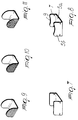
- the reference numeral 1 designates the slats of a roller blind provided with the interlocking retainer according to the invention.
- the slats 1 consist, in a known manner, of profiled elements made of plastics, aluminum, or steel, having a hook-shaped longitudinal portion 2 along the upper edge and a complementary grooved engagement seat 3 along the lower edge.
- the hook-shaped portion 2 of each slat 1 is adapted to be inserted in a corresponding engagement seat 3 of the adjacent slat.
- the slats 1 furthermore have a plurality of longitudinally aligned slots 4 at the hook-shaped edge 2.
- the interlocking retainer has an anchoring element 5 consisting of a practically U-shaped metal claw adapted to be applied to the hook-shaped portion 2 of the slat.
- the claw 5 has a bottom 5a and wings 5b with an appropriately rounded profile protruding therefrom.
- the wings 5b of the metal claw 5 are engageable with an opening 6 correspondingly formed on the engagement seat 3 of the adjacent slat. More specifically, said opening 6 is formed astride the outer edge of the portion of the profiled element forming the engagement seat 3 (see figure 3).
- the wings 5b of the metal claw 5 have respective pairs of teeth 7 formed by cutting and folding corresponding flaps of said wings. Said teeth 7 are adapted to ensure better locking and better stability of the claw 5 inside the opening 6.
- the metal claw 5 is conveniently applied at an end portion of each slat 6; in the working configuration, the wings 5b of the claw are arranged along planes perpendicular to the longitudinal axis of the slat.
- a chamfer 8 is formed on the profiled element forming the engagement seat 3 at the corresponding end of the slat to be associated with the preceding slat; said chamfer is adapted to facilitate the insertion of the claw.
- the slats 1 of the roller blind are provided, proximate to a corresponding end, with a respective metal claw 5, applied by pressing onto the hook-shaped longitudinal edge 2. It should be noted that the insertion of the metal claw 5 on the profiled element produces a deformation of said profiled element, so that the bottom 5a of the claw is co-planar with respect to said profiled element.
- the wings 5b of the claw protrude inside said hook-shaped longitudinal edge 2 of the slat.
- the slat 1 correspondingly has, on the opposite longitudinal edge, forming the engagement seat 3, the chamfer 8 and the opening 6 (see figure 5).
- the roller blind is assembled in a conventional manner by inserting the hook-shaped end 2 of the slats 1 in the complementarily shaped engagement seat 3 of the adjacent slats.
- the claw 5 engages the chamfer 8 of the profiled element forming said engagement seat 3, elastically deforming said profiled element until the wings 5b of the claw fit, in a snap-together manner, in the corresponding opening 6 (figure 6). This mutually anchors the two slats and prevents their subsequent sliding disengagement.
- Figure 7 illustrates a different embodiment of the metal claw 5, wherein the bottom 5a has a wider shape and the wings 5b have a flattened head. This configuration allows to better affect the opening 6 formed in the engagement seat 3 of the adjacent slat, improving interlocking retention.
- Said head of the wings 5a of the metal claw 5 conveniently has a slight concavity 9 (figure 8).
- the wings 5b have an appropriate surface finish that is adapted to improve the stability of the coupling.
- This surface finish consists for example of adapted linear or intersecting knurlings or of a plurality of fretted incisions.
- the described interlocking retainer allows easy and rapid assembly of the slats of the roller blinds.
- the retainer can be assembled very quickly and does not entail complicated handling of the slats.
- the device can be advantageously used with pre-perforated slats.
- the metal claw 5 can in fact also be applied at one of the slots 4 of the profiled element, as shown by way of example in figure 1. Accordingly, this allows the installer to purchase preperforated profiled bars to be cut to size when they are to be used, subsequently installing the interlocking retainer.
- the metal claws 5 are stably inserted in the slats 1, and therefore the effectiveness of the retainer is also ensured throughout the operating life of the roller blind.
- the device is furthermore very sturdy and has a proportionally very low cost.
- the materials employed, as well as the shape and the dimensions, may be any according to the requirements.
Landscapes
- Engineering & Computer Science (AREA)
- Structural Engineering (AREA)
- Architecture (AREA)
- Civil Engineering (AREA)
- Blinds (AREA)
- Operating, Guiding And Securing Of Roll- Type Closing Members (AREA)
Applications Claiming Priority (2)
| Application Number | Priority Date | Filing Date | Title |
|---|---|---|---|
| IT94BO000176A ITBO940176A1 (it) | 1994-04-22 | 1994-04-22 | Dispositivo di arresto antisfilamento per persiane avvolgibili |
| ITBO940176 | 1994-04-22 |
Publications (1)
| Publication Number | Publication Date |
|---|---|
| EP0678647A1 true EP0678647A1 (fr) | 1995-10-25 |
Family
ID=11339736
Family Applications (1)
| Application Number | Title | Priority Date | Filing Date |
|---|---|---|---|
| EP95105745A Withdrawn EP0678647A1 (fr) | 1994-04-22 | 1995-04-18 | Rétention pour un dispositif de verrouillage pour volets à rouleau |
Country Status (2)
| Country | Link |
|---|---|
| EP (1) | EP0678647A1 (fr) |
| IT (1) | ITBO940176A1 (fr) |
Cited By (2)
| Publication number | Priority date | Publication date | Assignee | Title |
|---|---|---|---|---|
| EP2857627A1 (fr) * | 2013-10-03 | 2015-04-08 | Regazzi SA | Volet roulant et procédé de production d'un volet roulant |
| WO2015155793A1 (fr) * | 2014-04-10 | 2015-10-15 | Cmvi Group Srl | Volet pliable comportant des lamelles pourvues d'un système innovant d'accouplement-accrochage mutuel pour fermer de façon sûre des ouvertures de bâtiments civils et industriels |
Citations (6)
| Publication number | Priority date | Publication date | Assignee | Title |
|---|---|---|---|---|
| CH531636A (de) * | 1970-11-17 | 1972-12-15 | Hardt Walter | Verfahren zum Zusammenbau eines Rolladenpanzers |
| DE2135078A1 (de) * | 1971-07-14 | 1973-01-25 | Theo Fest Fa | Kettenloser rolladen |
| DE2303525A1 (de) * | 1973-01-25 | 1974-08-01 | Fritz Janke | Selbsttaetig blockierende rolladen |
| CH573041A5 (en) * | 1974-01-09 | 1976-02-27 | Egloff & Notz Gmbh | Shaped interlocking suspended-element roller shutter - with T shaped clamp unit in upper element projecting into lower element's slit |
| AT357740B (de) * | 1974-10-22 | 1980-07-25 | Dyna Plastik Werke | Selbsttaetig blockierender rolladen |
| FR2579660A3 (fr) * | 1985-03-27 | 1986-10-03 | Citea Spa | Dispositif pour la stabilisation transversale d'un rideau enroulable avec lattes et coques appliquees |
-
1994
- 1994-04-22 IT IT94BO000176A patent/ITBO940176A1/it unknown
-
1995
- 1995-04-18 EP EP95105745A patent/EP0678647A1/fr not_active Withdrawn
Patent Citations (6)
| Publication number | Priority date | Publication date | Assignee | Title |
|---|---|---|---|---|
| CH531636A (de) * | 1970-11-17 | 1972-12-15 | Hardt Walter | Verfahren zum Zusammenbau eines Rolladenpanzers |
| DE2135078A1 (de) * | 1971-07-14 | 1973-01-25 | Theo Fest Fa | Kettenloser rolladen |
| DE2303525A1 (de) * | 1973-01-25 | 1974-08-01 | Fritz Janke | Selbsttaetig blockierende rolladen |
| CH573041A5 (en) * | 1974-01-09 | 1976-02-27 | Egloff & Notz Gmbh | Shaped interlocking suspended-element roller shutter - with T shaped clamp unit in upper element projecting into lower element's slit |
| AT357740B (de) * | 1974-10-22 | 1980-07-25 | Dyna Plastik Werke | Selbsttaetig blockierender rolladen |
| FR2579660A3 (fr) * | 1985-03-27 | 1986-10-03 | Citea Spa | Dispositif pour la stabilisation transversale d'un rideau enroulable avec lattes et coques appliquees |
Cited By (2)
| Publication number | Priority date | Publication date | Assignee | Title |
|---|---|---|---|---|
| EP2857627A1 (fr) * | 2013-10-03 | 2015-04-08 | Regazzi SA | Volet roulant et procédé de production d'un volet roulant |
| WO2015155793A1 (fr) * | 2014-04-10 | 2015-10-15 | Cmvi Group Srl | Volet pliable comportant des lamelles pourvues d'un système innovant d'accouplement-accrochage mutuel pour fermer de façon sûre des ouvertures de bâtiments civils et industriels |
Also Published As
| Publication number | Publication date |
|---|---|
| ITBO940176A0 (it) | 1994-04-22 |
| ITBO940176A1 (it) | 1995-10-22 |
Similar Documents
| Publication | Publication Date | Title |
|---|---|---|
| US6068040A (en) | Slat edge retainer for overhead rolling doors | |
| US4644721A (en) | Grille fastener system and method of using the same | |
| US5275381A (en) | Wire fencing with decorative slats that provide essentially complete privacy | |
| EP2951366B1 (fr) | Agrafe pour boiserie périmétrique | |
| US20170259970A1 (en) | Band Clamp | |
| US4180347A (en) | Four branch spring steel jam fastener clip for assembly of open extrusions | |
| US5234199A (en) | Chain link fencing with decorative slats | |
| US5165664A (en) | Chain link fencing with decorative slats | |
| USRE36085E (en) | Chain link fencing with decorative slats that provide complete privacy | |
| US5799647A (en) | Oven door window unit | |
| GB2233697A (en) | Glazing retainer | |
| EP3039215B1 (fr) | Pince de fixation et procédé de fixation d'un cadre de finition contre un châssis d'une fenêtre ou similaires et fenêtre munie d'une telle pince de fixation | |
| EP0644312A2 (fr) | Equerre pour assemblages d'angle droit de profilés métalliques pour cadres de portes et fenêtres ou similaires | |
| CA2339724C (fr) | Insert en forme d'assiette pour stores enroulables ou autres profiles | |
| EP1312746A1 (fr) | Fixation contre extraction longitudinale pour volets roulants | |
| CN215212800U (zh) | 卡簧、传动杆与门锁 | |
| US6305144B1 (en) | Window frame and method | |
| NL2038146B1 (en) | Frame-securing clip | |
| US5471793A (en) | Adjustable astragal weathering for operable doors and windows | |
| DE10237006B4 (de) | Kasten zur Aufnahme eines aufwickelbaren Behangs. | |
| AU681639B2 (en) | Bridging member | |
| EP0474581B1 (fr) | Grille de ventilation | |
| AU750220B2 (en) | Improved bridging member | |
| EP2233678A1 (fr) | Maillon d'attache pour persiennes | |
| ITBO940176A1 (it) | Dispositivo di arresto antisfilamento per persiane avvolgibili |
Legal Events
| Date | Code | Title | Description |
|---|---|---|---|
| PUAI | Public reference made under article 153(3) epc to a published international application that has entered the european phase |
Free format text: ORIGINAL CODE: 0009012 |
|
| AK | Designated contracting states |
Kind code of ref document: A1 Designated state(s): AT BE DE FR |
|
| 17P | Request for examination filed |
Effective date: 19960409 |
|
| 17Q | First examination report despatched |
Effective date: 19970313 |
|
| STAA | Information on the status of an ep patent application or granted ep patent |
Free format text: STATUS: THE APPLICATION HAS BEEN WITHDRAWN |
|
| 18W | Application withdrawn |
Withdrawal date: 19971023 |