EP0678663A1 - Verfahren und Erzeuger für Dampfionen - Google Patents
Verfahren und Erzeuger für Dampfionen Download PDFInfo
- Publication number
- EP0678663A1 EP0678663A1 EP94300091A EP94300091A EP0678663A1 EP 0678663 A1 EP0678663 A1 EP 0678663A1 EP 94300091 A EP94300091 A EP 94300091A EP 94300091 A EP94300091 A EP 94300091A EP 0678663 A1 EP0678663 A1 EP 0678663A1
- Authority
- EP
- European Patent Office
- Prior art keywords
- ion vapor
- generator
- generators
- activating
- vapor
- Prior art date
- Legal status (The legal status is an assumption and is not a legal conclusion. Google has not performed a legal analysis and makes no representation as to the accuracy of the status listed.)
- Withdrawn
Links
- 238000000034 method Methods 0.000 title claims abstract description 14
- 238000002485 combustion reaction Methods 0.000 claims abstract description 49
- 239000007788 liquid Substances 0.000 claims abstract description 40
- 150000002500 ions Chemical class 0.000 claims description 121
- 238000004519 manufacturing process Methods 0.000 claims description 17
- 230000003213 activating effect Effects 0.000 claims description 14
- 230000004913 activation Effects 0.000 claims description 10
- 239000012080 ambient air Substances 0.000 claims description 7
- MYMOFIZGZYHOMD-UHFFFAOYSA-N Dioxygen Chemical compound O=O MYMOFIZGZYHOMD-UHFFFAOYSA-N 0.000 claims description 2
- -1 hydroxide ions Chemical class 0.000 claims description 2
- 229910001882 dioxygen Inorganic materials 0.000 claims 1
- 239000002803 fossil fuel Substances 0.000 abstract description 5
- 239000003570 air Substances 0.000 description 18
- XLYOFNOQVPJJNP-UHFFFAOYSA-N water Chemical compound O XLYOFNOQVPJJNP-UHFFFAOYSA-N 0.000 description 14
- 238000005381 potential energy Methods 0.000 description 6
- 238000006243 chemical reaction Methods 0.000 description 5
- QVGXLLKOCUKJST-UHFFFAOYSA-N atomic oxygen Chemical compound [O] QVGXLLKOCUKJST-UHFFFAOYSA-N 0.000 description 4
- 238000012986 modification Methods 0.000 description 4
- 230000004048 modification Effects 0.000 description 4
- 230000002708 enhancing effect Effects 0.000 description 3
- 238000005259 measurement Methods 0.000 description 3
- 239000001301 oxygen Substances 0.000 description 3
- 229910052760 oxygen Inorganic materials 0.000 description 3
- CURLTUGMZLYLDI-UHFFFAOYSA-N Carbon dioxide Chemical compound O=C=O CURLTUGMZLYLDI-UHFFFAOYSA-N 0.000 description 2
- MWUXSHHQAYIFBG-UHFFFAOYSA-N Nitric oxide Chemical compound O=[N] MWUXSHHQAYIFBG-UHFFFAOYSA-N 0.000 description 2
- ATUOYWHBWRKTHZ-UHFFFAOYSA-N Propane Chemical compound CCC ATUOYWHBWRKTHZ-UHFFFAOYSA-N 0.000 description 2
- 238000013019 agitation Methods 0.000 description 2
- 230000005587 bubbling Effects 0.000 description 2
- 230000003247 decreasing effect Effects 0.000 description 2
- 230000000694 effects Effects 0.000 description 2
- 239000000446 fuel Substances 0.000 description 2
- 230000008569 process Effects 0.000 description 2
- 230000009467 reduction Effects 0.000 description 2
- 230000000284 resting effect Effects 0.000 description 2
- 239000004215 Carbon black (E152) Substances 0.000 description 1
- UGFAIRIUMAVXCW-UHFFFAOYSA-N Carbon monoxide Chemical compound [O+]#[C-] UGFAIRIUMAVXCW-UHFFFAOYSA-N 0.000 description 1
- 230000002730 additional effect Effects 0.000 description 1
- 230000003416 augmentation Effects 0.000 description 1
- 230000004888 barrier function Effects 0.000 description 1
- 239000001273 butane Substances 0.000 description 1
- 239000006227 byproduct Substances 0.000 description 1
- 229910002092 carbon dioxide Inorganic materials 0.000 description 1
- 239000001569 carbon dioxide Substances 0.000 description 1
- 229910002091 carbon monoxide Inorganic materials 0.000 description 1
- 230000003197 catalytic effect Effects 0.000 description 1
- 239000000356 contaminant Substances 0.000 description 1
- 230000008878 coupling Effects 0.000 description 1
- 238000010168 coupling process Methods 0.000 description 1
- 238000005859 coupling reaction Methods 0.000 description 1
- 230000001351 cycling effect Effects 0.000 description 1
- 230000007423 decrease Effects 0.000 description 1
- 239000008367 deionised water Substances 0.000 description 1
- 229910021641 deionized water Inorganic materials 0.000 description 1
- 239000002283 diesel fuel Substances 0.000 description 1
- 238000005516 engineering process Methods 0.000 description 1
- 239000007789 gas Substances 0.000 description 1
- 239000003502 gasoline Substances 0.000 description 1
- 230000036541 health Effects 0.000 description 1
- 229930195733 hydrocarbon Natural products 0.000 description 1
- 150000002430 hydrocarbons Chemical class 0.000 description 1
- XLYOFNOQVPJJNP-UHFFFAOYSA-M hydroxide Chemical compound [OH-] XLYOFNOQVPJJNP-UHFFFAOYSA-M 0.000 description 1
- 208000015181 infectious disease Diseases 0.000 description 1
- 230000002458 infectious effect Effects 0.000 description 1
- 238000009434 installation Methods 0.000 description 1
- 239000002085 irritant Substances 0.000 description 1
- 231100000021 irritant Toxicity 0.000 description 1
- 239000003949 liquefied natural gas Substances 0.000 description 1
- 230000007774 longterm Effects 0.000 description 1
- 230000007246 mechanism Effects 0.000 description 1
- 229910052751 metal Inorganic materials 0.000 description 1
- 239000002184 metal Substances 0.000 description 1
- IJDNQMDRQITEOD-UHFFFAOYSA-N n-butane Chemical compound CCCC IJDNQMDRQITEOD-UHFFFAOYSA-N 0.000 description 1
- OFBQJSOFQDEBGM-UHFFFAOYSA-N n-pentane Natural products CCCCC OFBQJSOFQDEBGM-UHFFFAOYSA-N 0.000 description 1
- 235000019645 odor Nutrition 0.000 description 1
- 239000004033 plastic Substances 0.000 description 1
- 230000002035 prolonged effect Effects 0.000 description 1
- 239000001294 propane Substances 0.000 description 1
- 230000003252 repetitive effect Effects 0.000 description 1
- 238000011160 research Methods 0.000 description 1
- 230000029058 respiratory gaseous exchange Effects 0.000 description 1
- 238000005070 sampling Methods 0.000 description 1
- 238000012360 testing method Methods 0.000 description 1
Images



Classifications
-
- F—MECHANICAL ENGINEERING; LIGHTING; HEATING; WEAPONS; BLASTING
- F02—COMBUSTION ENGINES; HOT-GAS OR COMBUSTION-PRODUCT ENGINE PLANTS
- F02M—SUPPLYING COMBUSTION ENGINES IN GENERAL WITH COMBUSTIBLE MIXTURES OR CONSTITUENTS THEREOF
- F02M25/00—Engine-pertinent apparatus for adding non-fuel substances or small quantities of secondary fuel to combustion-air, main fuel or fuel-air mixture
- F02M25/022—Adding fuel and water emulsion, water or steam
- F02M25/032—Producing and adding steam
-
- Y—GENERAL TAGGING OF NEW TECHNOLOGICAL DEVELOPMENTS; GENERAL TAGGING OF CROSS-SECTIONAL TECHNOLOGIES SPANNING OVER SEVERAL SECTIONS OF THE IPC; TECHNICAL SUBJECTS COVERED BY FORMER USPC CROSS-REFERENCE ART COLLECTIONS [XRACs] AND DIGESTS
- Y02—TECHNOLOGIES OR APPLICATIONS FOR MITIGATION OR ADAPTATION AGAINST CLIMATE CHANGE
- Y02T—CLIMATE CHANGE MITIGATION TECHNOLOGIES RELATED TO TRANSPORTATION
- Y02T10/00—Road transport of goods or passengers
- Y02T10/10—Internal combustion engine [ICE] based vehicles
- Y02T10/12—Improving ICE efficiencies
Definitions
- the present invention relates generally to improvements in combustion processes, and more particularly to an improved apparatus and method for generating negatively charged ion-containing vapor for enhancing efficiency of fossil fuel combustion.
- other utilities are also contemplated by the present invention, including, for example, in health fields related to control of infectious air-borne contaminants, irritants to breathing, odors, and the like.
- the predominant contribution to enhancing combustion efficiency may come, not from a negatively charged hydroxide ion (OH ⁇ ) but rather from negatively charged oxygen molecules, i.e. O2 ⁇ .
- O2 ⁇ negatively charged oxygen molecules
- the inclusion of negatively charged oxygen molecules in a combustion reaction reduces the activation energy required to begin and/or continue combustion by the amount of potential energy of the ionic species.
- the ionic species O2 ⁇ carries a potential energy of 42 kJ/mol which is released during combustion. The release of this potential energy reduces the activation energy required for combustion by the amount of potential energy released.
- the actual activation energy required for combustion is reduced to only 31.3 kJ/mol (that is, (73.3 - 42) kJ/mol).
- This reduction of required combustion activation energy is thought to increase the efficiency of the combustion process by enabling combustion to occur at a much faster pace, result in improved flame stability, and permit actual combustion with excess air close to stoichiometry. Greater combustion efficiency results in decreased production of polluting by-products, such as nitric oxide, carbon dioxide, and carbon monoxide, as well as decreased fuel consumption per uniform combustion heat output.
- ion vapor generators usable to enhance fossil fuel combustion efficiency are described in U.S. Patents Nos. 3,862,819, 4,016,837, 4,410,467, and 4,952,340, 5,211,890, 5,246,632 and 5,255,514, which are incorporated herein by reference. All of the generators described these patents produce negative ion vapor from a quantity of water-including liquid contained within the generator. However, the quantity of negative ions produced by negative ion generators such as described in the foregoing patents decreases after long periods of continuous ion vapor generation from the same quantity of water. And, under conditions of extremely prolonged use, production of negatively charged ions may fall off significantly.
- a more specific object of the present invention is to provide an improved apparatus and method for generating negative ion vapor, e.g. for use in enhancing combustion efficiency.
- an apparatus made according to this aspect of the present invention comprises at least one negative ion vapor generator for generating negatively charged ion vapor from water-including liquid.
- Means are provided for activating and de-activating the at least one generator whereby to permit the liquid to "rest", periodically, between periods of active generation.
- the present invention comprises a plurality of negative ion vapor generators for generating negatively charged ion vapor from water-including liquid, and having their respective outlets connected to a common manifold, e.g. for delivery to a combustion process.
- Means are provided for selectively activating and de-activating the individual generators whereby to permit the liquid in the individual generators to "rest", periodically, between periods of active generation.
- the means for selectively activating and de-activating are arranged so that at least one generator is running and producing negative ion vapor at desired levels at all times.
- At least two negative ion vapor generators are connected together whereby the negative ion vapor output from the first generator is delivered to the head-space region of a second negative ion vapor generator.
- Cascading negative ion vapor generators in this manner results in the generation of a multiple of the amount of negative ions, as compared to the amount that could be produced by the sum of the generators separately. For example, connecting two like size generators together results in the production of, not twice, but approximately four times the amount of negative ions.
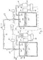
- FIG. 3 illustrates one preferred embodiment of an apparatus according to the first aspect of the present invention.
- the apparatus comprises at least one 10A conventional negative ion vapor generator, and preferably a plurality 10A, 10B of conventional negative ion vapor generators for generating vapor containing negatively charged ions (OH ⁇ and O2 ⁇ ) from a water-containing liquid.
- the negative ion vapor generators 10A, 10B shown in Figure 3 are of the vibratory-type described in U.S. Patent No. 4,952,340, other types of negative ion vapor generators may be used in an apparatus according to the first aspect of the present invention, without departing therefrom.
- Generators 10A, 10B may be of essentially identical size and capacity, or may be of different size and capacity.
- Generators 10A, 10B respectively comprise liquid containers 12A, 12B partially filled with a liquid 14A, 14B which contains water.
- Vibration means 19A, 19B respectively coupled to containers 12A, 12B by conventional coupling means 20A, 20B, cause the surfaces 16A, 16B of liquid 14A, 14B to be agitated with a resulting rippling effect.
- the vibratory levels, frequency and amplitude are adjusted so as to maintain substantially continuous surface tension on liquid surfaces 16A, 16B, as described in the aforesaid '340 patent. This agitation causes negative ions to be released from liquid 14A, 14B and out through surfaces 16A, 16B.
- Elevated levels of surface agitation that lead to substantial disruption of the surface tension will (1) significantly limit the effective generation of negative ions and/or (2) cause undesired levels of positive ions to be generated in place of negative ions, defeating the purpose of the negative ion generator.
- At the top of containers 12A, 12B are respective head-spaces 15A, 15B where the negative ion vapor accumulates after liberation from the liquid 14A, 14B of generators 10A, 10B.
- ambient air 31A is drawn into air pump 21A via air inlet 22A.
- the air is then pumped from pump 21A through opening 33A into head-space 15A of generator 10A via conduit 24A.
- the positive pressure of ambient air thus provided to head-space 15A causes ion vapor generated therein to be driven from head-space 15A of container 12A through outlet 34A and into conduit 4A for delivery to a desired location 32, which preferably comprises a combustion process such as an engine or burner (not shown).
- ambient air 32B is drawn into air pump 21B via air inlet 22B, and is pumped from pump 21B through opening 33B into head-space 15B of generator 10B via conduit 24B.
- the positive pressure of ambient air thus provided to head-space 15B causes ion vapor generated therein to be driven from head-space 15B of container 12B through outlet 34B and into conduit 4B for delivery to location 32.
- means 11A, 11B are provided for selectively activating and de-activating generators 10A and 10B, in turn, for predetermined active and inactive periods, respectively, so as to permit the liquid 14A and 14B to "rest” for a period of time, thereby to avoid “overusing” the liquid which will result in a reduction in the rate of generation of negatively charged ion vapor. Resting the liquid for a period of time permits the liquid to "autoregenerate" itself to a balanced state, comparable to that at start-up, for favoring production of negative ion vapor.
- means 11A and 11B comprise conventional timer-switches or counters coupled to generators 10A and 10B, respectively, to switch the respective generator “on” and “off” in repetitive, predetermined active and inactive periods of time.
- Timer-switches 11A and 11B may be electrically coupled to pump 21A and vibrator 19A, and to pump 21B and vibrator 19B, respectively, to activate and de-activate them simultaneously, so as to cycle generators 10A and 10B, respectively, through periods of activity and inactivity, respectively.
- the periods of the on and off cycles depend on various factors including the size of the ion generator and quantity of liquid therein.
- Switches 11A, 11B preferably are programmable and permit their respective generators 10A and 10B to be activated and de-activated alternatively, that is, generators 10A and 10B are cycled "on” and "off", in timed sequence so that at least one generator is producing ion vapor at any given time, according to a predetermined timing sequence.
- the alternate cycling of generators 10A, 10B permits ion vapor to be continuously and efficiently produced and supplied to combustion space 32, while permitting the water 14A, 14B in the inactive generator to rest for sufficient time to autoregenerate to a balanced state favoring production of negative ion vapor.
- the "rest" period should be no longer than, and preferably will be somewhat shorter than the activating period so that the newly started generator may come-up essentially to full charge so that there is no "dead” period in which little or no negative ion vapor is being produced.
- timer-switches 11C, 11D controlled valves 17A, 17B may be disposed in conduits 4A, 4B.
- each timer-switch 11C, 11D is programmed to synchronize opening and closing of its respective valve 17A, 17B, as needed, to prevent flow of ion vapor from an active generator to an inactive generator and thus permit substantially all of the ion vapor generated by the active generator to be delivered to the combustion space 32.
- valve 17A should be opened and valve 17B closed.
- valves 17A, 17B shown in Figure 3 is merely for illustrative purposes and valves 17A, 17B may be disposed elsewhere in conduits 4A, 4B.
- the apparatus comprises at least two ion generators 10A, 10B of the vibratory type, i.e. as described in aforesaid '340 patent.
- ion generators 10A, 10B of the vibratory type, i.e. as described in aforesaid '340 patent.
- Air pump 21A draws ambient air 31A through conduit 22A and pumps the air into head-space 15A via inlet 33A through conduit 24A.
- Positive pressure in head-space 15A forces ion vapor generated in the head-space 15A of generator 10A through conduit 6 to the head-space 15B of generators 10B.
- conduit 6 is made of metal or plastic and connects inlet 34A of generator 10A to the head-space 15B of generator 10B.
- a conventional air pump (not shown) may be operatively disposed in conduit 6 to force ion vapor generated in head-space 15A through the conduit to the head-space 15B of generator 10B.
- the negative ion vapor generated by the generator apparatus may be withdrawn via conduit 4 and delivered to a desired location 32, such as a fossil fuel combustion space, driven from generator 10B by positive air pressure supplied by air pump 21A and/or an optional air pump (not shown) which may be operatively disposed in conduit 4 or conduit 6.
- a desired location 32 such as a fossil fuel combustion space
- air pump 21A and/or an optional air pump (not shown) which may be operatively disposed in conduit 4 or conduit 6.
- vacuum suction or draw from combustion space 32 may be used to move the negative ion vapor.
- generator 10B also may comprise air pressure equalization means 38 for drawing ambient air 31B into the head-space 15B of generator 10B.
- Equalization means 38 includes inlets 33B, 33B' in container 12B.
- either one 33B' or both 33B, 33B' of the inlets may include one-way flow valve or stopper 38'.
- Equalization means 38 permits the pressure of head-space 15B to be equalized with respect to the ambient environment, despite suction from combustion space 32.
- FIGs 5-7 illustrate preferred ways of applying a negative ion vapor generating system of the present invention to various conventional fossil fuel combustion devices to increase the respective combustion efficiencies thereof.
- negative ion vapor generated by a negative ion vapor generating system 80 such as described in Figure 3 or Figure 4 is delivered through feed line 54 to the desired location 32, which in this case, is a combustion region 52 of the burner 50, which may be fueled, for example by oil.
- FIG. 6 Application of the negative ion vapor generating system 80 to a gas-fired burner 60 is shown in Figure 6.
- the negative ion vapor generated by generating system 80 is feed via line 64 to the desired location 32, which in this case is the combustion region 62 of the gas burner 60.
- Negative ion vapor generated by generating system 80 is delivered to the air intake 74 of engine 70 via feed line 72, and enters the engine 70 along with normal intake air.
- the engine 70 may be of the type fueled with gasoline, diesel oil, liquefied natural gas, propane, butane, and/or the like.
- the container of a vibratory ion vapor generator of the type described in U.S. Patent No. 4,952,340 was partially (75%) filled with a volume of deionized water. When placed in the container, the water had a surface area of 413 sq. cm. Ambient humidity was 62%.
- a magnetic vibrator (which was set for 60 Hz) was used to impart vibratory energy to the wall of the container, which in turn generated vibrations in the water.
- the vibrator was attached to a timer-switch which was set to cycle the generator "on” and "off” for periods of 1/2 hour and 1/2 hours, respectively, over a total time of 200 hours. A constant quantity of 3500 cc.
- Example 1 The procedure of Example 1 was followed, but with the periods of "on” and “off” cycles varied from 10:1 to 1:1. Negative ion production was measured as before using an electrometer, and the results recorded in Table 1.
- means 11A, 11B in Figure 3 are shown as separate and distinct, they may comprise separate controllable switches connected to a unitary, central programmable controller.
- means 11C, 11D may also comprise controllable switches connected to a unitary, central controller, and indeed, means 11A, 11B, 11C, and/or 11D may all comprise switches controlled by a unitary, central programmable controller.
- generators 10A and 10B may share a common air pump 21A.
- Generator 14A is turned on and run for a sufficient time to reach essentially steady state operation as determined by electrometer readings taken at 120A.
- Valve 17A is adjusted to permit slightly less than 100% of the negative ions vapor, for example, 95% to pass to combustion space 32. The balance may be bled off at valve 17A. Electrometer readings are maintained on real time, and when negative ion production begins to fall from generator 14A, e.g. to 97%, valve 17A is opened further to compensate for the falling production, and generator 14B is cycled on. However, all of the output from generator 14B is diverted by valve 17B until such time as generator 14B is running at full production.
- valve 17A is closed, and generator 14A is switched off and allowed to rest. Simultaneously with closing of valve 17A, valve 17B is opened and adjusted to permit 95% of the output of generator 14B to flow to combustion space 32. Generator 14B is then run continuously until its output, as sensed by electrometer 120B falls to about 97%, at which time valve 17B is opened to further compensate for falling production, and generator 14A is reactivated. Once generator 14A reaches full production and the output from generator 14B drops to 95%, valve 14B is closed simultaneously with the opening of valve 17A whereby to permit 95% of the output from generator 14A to pass therethrough, and generator 14B is deactivated to rest. The entire operation is controlled through a suitable feedback loop (Figure 9). The result is plotted in Figure 10.
- generators 14A and 14B are simply cycled on and off according to predetermined cycle, the control of which is affected by computer generated program stored in CPU 100. Cycle times may be determined by emperically measuring output of negatively charged ions from the generators, and adjusting run and rest times to provide a desired steady state production level.
- the invention has been described in the preferred embodiment employing vibratory negative ion generators, the invention also advantageously may be employed using one or more bubble type generators or circulatory generators. And, in order to obtain fasten turn-around times, the liquid in the resting generator may be drained, and replaced with fresh liquid.
Landscapes
- Engineering & Computer Science (AREA)
- Chemical & Material Sciences (AREA)
- Combustion & Propulsion (AREA)
- Mechanical Engineering (AREA)
- General Engineering & Computer Science (AREA)
- Physical Or Chemical Processes And Apparatus (AREA)
- Disinfection, Sterilisation Or Deodorisation Of Air (AREA)
Priority Applications (3)
| Application Number | Priority Date | Filing Date | Title |
|---|---|---|---|
| EP94300091A EP0678663A1 (de) | 1994-01-06 | 1994-01-06 | Verfahren und Erzeuger für Dampfionen |
| AU15982/95A AU1598295A (en) | 1994-01-06 | 1995-01-03 | Ion vapor generating apparatus and method |
| PCT/US1995/000119 WO1995018919A1 (en) | 1994-01-06 | 1995-01-03 | Ion vapor generating apparatus and method |
Applications Claiming Priority (1)
| Application Number | Priority Date | Filing Date | Title |
|---|---|---|---|
| EP94300091A EP0678663A1 (de) | 1994-01-06 | 1994-01-06 | Verfahren und Erzeuger für Dampfionen |
Publications (1)
| Publication Number | Publication Date |
|---|---|
| EP0678663A1 true EP0678663A1 (de) | 1995-10-25 |
Family
ID=8217521
Family Applications (1)
| Application Number | Title | Priority Date | Filing Date |
|---|---|---|---|
| EP94300091A Withdrawn EP0678663A1 (de) | 1994-01-06 | 1994-01-06 | Verfahren und Erzeuger für Dampfionen |
Country Status (3)
| Country | Link |
|---|---|
| EP (1) | EP0678663A1 (de) |
| AU (1) | AU1598295A (de) |
| WO (1) | WO1995018919A1 (de) |
Cited By (1)
| Publication number | Priority date | Publication date | Assignee | Title |
|---|---|---|---|---|
| EP0869317A1 (de) * | 1997-04-01 | 1998-10-07 | Ionic Fuel Technology, Inc. | Vorrichtung und Verfahren zur Leistungsverbesserung von mit Gasbrenner befeuerten Reaktoren |
Families Citing this family (1)
| Publication number | Priority date | Publication date | Assignee | Title |
|---|---|---|---|---|
| WO2009070132A1 (en) * | 2007-11-27 | 2009-06-04 | Ahern Brian S | Charged water fumigation for combustion systems |
Citations (3)
| Publication number | Priority date | Publication date | Assignee | Title |
|---|---|---|---|---|
| US3107657A (en) * | 1962-02-16 | 1963-10-22 | Cook Daniel | Device for supplying moisture-laden air to the intake manifold of an internal combustion engine |
| US4257989A (en) * | 1979-02-22 | 1981-03-24 | Tdk Electronics Co., Ltd. | Humidifier |
| US4952340A (en) * | 1989-12-04 | 1990-08-28 | Wentworth Fred Albert Jr | Vibratory ion vapor generator and method |
-
1994
- 1994-01-06 EP EP94300091A patent/EP0678663A1/de not_active Withdrawn
-
1995
- 1995-01-03 WO PCT/US1995/000119 patent/WO1995018919A1/en not_active Ceased
- 1995-01-03 AU AU15982/95A patent/AU1598295A/en not_active Abandoned
Patent Citations (3)
| Publication number | Priority date | Publication date | Assignee | Title |
|---|---|---|---|---|
| US3107657A (en) * | 1962-02-16 | 1963-10-22 | Cook Daniel | Device for supplying moisture-laden air to the intake manifold of an internal combustion engine |
| US4257989A (en) * | 1979-02-22 | 1981-03-24 | Tdk Electronics Co., Ltd. | Humidifier |
| US4952340A (en) * | 1989-12-04 | 1990-08-28 | Wentworth Fred Albert Jr | Vibratory ion vapor generator and method |
Cited By (1)
| Publication number | Priority date | Publication date | Assignee | Title |
|---|---|---|---|---|
| EP0869317A1 (de) * | 1997-04-01 | 1998-10-07 | Ionic Fuel Technology, Inc. | Vorrichtung und Verfahren zur Leistungsverbesserung von mit Gasbrenner befeuerten Reaktoren |
Also Published As
| Publication number | Publication date |
|---|---|
| AU1598295A (en) | 1995-08-01 |
| WO1995018919A1 (en) | 1995-07-13 |
Similar Documents
| Publication | Publication Date | Title |
|---|---|---|
| US8287716B2 (en) | Desalination system and method | |
| WO2005108761A3 (en) | Evap canister purge prediction for engine fuel and air control | |
| RU94019339A (ru) | Способ и устройство дозирования топлива, способ дозирования текучих сред и устройство для его осуществления | |
| CN207187506U (zh) | 一种高效电化脱硝器 | |
| CN104421020A (zh) | 蒸汽净化辛烷值分离系统 | |
| EP0678663A1 (de) | Verfahren und Erzeuger für Dampfionen | |
| CN101413444A (zh) | 供以气化燃料的发动机 | |
| EP0504256B1 (de) | Verfahren und vibrationserzeuger für dampfionen | |
| MY143727A (en) | System for generating hybrid fuel for a combustion engine | |
| US5211890A (en) | Circulatory ion vapor generator and method | |
| US7444998B2 (en) | Hydrogen-oxygen plasma engines and dosing methods therefor | |
| CN206823198U (zh) | 一种跑动火龙装置 | |
| CN109621694A (zh) | 氨基酸发酵产生尾气的处理工艺 | |
| RU94017515A (ru) | Способ регулирования газожидкостного двигателя внутреннего сгорания | |
| CN222010368U (zh) | 一种实验室用油箱燃油蒸发吸附脱附系统 | |
| CN217921488U (zh) | 新型负氧离子制氧机 | |
| KR101307602B1 (ko) | 내연기관용 음이온 발생장치 | |
| SU1562509A1 (ru) | Способ питани дизел и система дл его осуществлени | |
| JPS5672232A (en) | Mixed-gas supply unit of engine | |
| CN212403517U (zh) | 一种污水处理装置 | |
| RU2053403C1 (ru) | Устройство подготовки топлива для двигателя автомобиля | |
| Syamsuri et al. | The effect of NaOH loading on the performance of the vario 125 engine with a biogas fuel | |
| RU93043684A (ru) | Система питания карбюраторного двигателя внутреннего сгорания | |
| CN204755071U (zh) | 一种利用沼气的发电装置 | |
| JPS57131853A (en) | Air fuel ratio control process and device for internal combustion engine of low temperature liquefied gas |
Legal Events
| Date | Code | Title | Description |
|---|---|---|---|
| PUAI | Public reference made under article 153(3) epc to a published international application that has entered the european phase |
Free format text: ORIGINAL CODE: 0009012 |
|
| 17P | Request for examination filed |
Effective date: 19941104 |
|
| AK | Designated contracting states |
Kind code of ref document: A1 Designated state(s): AT BE CH DE DK ES FR GB GR IE IT LI LU MC NL PT SE |
|
| STAA | Information on the status of an ep patent application or granted ep patent |
Free format text: STATUS: THE APPLICATION IS DEEMED TO BE WITHDRAWN |
|
| 18D | Application deemed to be withdrawn |
Effective date: 19950927 |