EP0678672A1 - Durchflusssteuervorrichtung für Servolenkung - Google Patents
Durchflusssteuervorrichtung für Servolenkung Download PDFInfo
- Publication number
- EP0678672A1 EP0678672A1 EP95400507A EP95400507A EP0678672A1 EP 0678672 A1 EP0678672 A1 EP 0678672A1 EP 95400507 A EP95400507 A EP 95400507A EP 95400507 A EP95400507 A EP 95400507A EP 0678672 A1 EP0678672 A1 EP 0678672A1
- Authority
- EP
- European Patent Office
- Prior art keywords
- spool
- pressure
- sub
- valve
- hydraulic fluid
- Prior art date
- Legal status (The legal status is an assumption and is not a legal conclusion. Google has not performed a legal analysis and makes no representation as to the accuracy of the status listed.)
- Granted
Links
- 230000007246 mechanism Effects 0.000 title claims abstract description 25
- 239000012530 fluid Substances 0.000 claims abstract description 32
- 238000002485 combustion reaction Methods 0.000 description 4
- 238000000034 method Methods 0.000 description 3
- 230000003213 activating effect Effects 0.000 description 2
- 230000002411 adverse Effects 0.000 description 1
- 238000007796 conventional method Methods 0.000 description 1
- 238000013016 damping Methods 0.000 description 1
- 238000006073 displacement reaction Methods 0.000 description 1
- 230000000694 effects Effects 0.000 description 1
- 238000009434 installation Methods 0.000 description 1
Images


Classifications
-
- F—MECHANICAL ENGINEERING; LIGHTING; HEATING; WEAPONS; BLASTING
- F04—POSITIVE - DISPLACEMENT MACHINES FOR LIQUIDS; PUMPS FOR LIQUIDS OR ELASTIC FLUIDS
- F04C—ROTARY-PISTON, OR OSCILLATING-PISTON, POSITIVE-DISPLACEMENT MACHINES FOR LIQUIDS; ROTARY-PISTON, OR OSCILLATING-PISTON, POSITIVE-DISPLACEMENT PUMPS
- F04C14/00—Control of, monitoring of, or safety arrangements for, machines, pumps or pumping installations
- F04C14/24—Control of, monitoring of, or safety arrangements for, machines, pumps or pumping installations characterised by using valves controlling pressure or flow rate, e.g. discharge valves or unloading valves
- F04C14/26—Control of, monitoring of, or safety arrangements for, machines, pumps or pumping installations characterised by using valves controlling pressure or flow rate, e.g. discharge valves or unloading valves using bypass channels
-
- B—PERFORMING OPERATIONS; TRANSPORTING
- B62—LAND VEHICLES FOR TRAVELLING OTHERWISE THAN ON RAILS
- B62D—MOTOR VEHICLES; TRAILERS
- B62D5/00—Power-assisted or power-driven steering
- B62D5/06—Power-assisted or power-driven steering fluid, i.e. using a pressurised fluid for most or all the force required for steering a vehicle
- B62D5/062—Details, component parts
Definitions
- the present invention relates to a mechanism for a power steering device of automobiles.
- the present invention relates to a flow control mechanism for power steering in which there is formed a combination consisting of: a valve for controlling the flow amount of the hydraulic fluid to be supplied to the power steering device by a pump (which is driven by the engine); and a valve installed for protecting the hydraulic circuit and for a stable operation of the pump.
- a vane pump is widely used as the power steering pump, and this pump is driven by an internal combustion engine which is installed on the automobile.
- the hydraulic fluid is sucked by the pump so as to produce a pressure,and,by utilizing this pressure,the manual steering torque is controlled.
- the power steering device when the vehicle runs slow or is stopped, a sufficient steering force is required, because the ground contact resistance acts in a high degree.
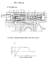
- FIG. 1A is a sectional view showing a conventional apparatus.
- the hydraulic fluid which is discharged by a pump passes through an inlet fluid path 1, a main orifice 2,a first orifice 3 formed in a sub-spool 5 and a second orifice 4 to be supplied to an actuator.
- the control of the hydraulic fluid which is supplied to the actuator is done in such a manner that the sub-spool 5 move to the left owing to the pressure difference produced between the front and the rear of the first orifice 3 and the second orifice 4,and that the sectional area is reduced owing to the movement of the spool 5.
- the extra discharge amount from the pump is bypassed, because a main spool 6 moves to the right by the elastic force of a spring 8 which supports the main spool 6.
- the flow amount Q2 is supplied to the actuator,thereby assuring a stability during the steering.
- a tapered portion 12c and projected portions 12a and 12b which are formed on the sub-spool 5 may cause a variation of the aperture area. Consequently, an imbalance is caused in the orifice characteristics, so that the characteristics of the sub-spool 5 may be affected, and that the hydraulic fluid supplied to the actuator would become unstable. Consequently,the stability of the power steering is adversely affected.
- the aperture area of the main orifice 2 is varied in a linear form over a certain region,but if the region is departed,the variation becomes non-linear,with the result that an accurate hydraulic control becomes difficult.Further,the pressure pulse of the pump can be transmitted to the actuator.
- the present invention is intended to overcome the above described disadvantages of the conventional techniques.
- FIG. 1 illustrates the conventional mechanism, in which: FIG. 1A is a sectional view of the conventional apparatus; and FIG. 1B is a graphical illustration showing the flow amount characteristics.
- the flow control mechanism for the power steering device includes a pump and a valve body which are integrally formed.
- the valve body is provided with an accommodating hole 18 for accommodating a main spool 6 into which a sub-spool 5 is inserted.Thus the overall bulk is reduced, and the energy saving characteristics becomes superior.Further, a relief valve 21 which is for protecting the circuit is exposed to the outside,so that its set pressure can be tested even in the assembled state.
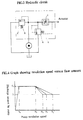
- FIG. 3 illustrates a hydraulic circuit for activating the control valve.
- FIG. 4 illustrates the flow amount characteristics for the preferred embodiment of the present invention.
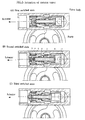
- FIG. 5 illustrates the actuating state of the spool for the control valve.
- the hydraulic fluid which is discharged by the pump passes through an inlet fluid path 1 and a main orifice 2 to be supplied to a first orifice 3 and a second orifice 4 which are formed on the sub-spool 5. Then the hydraulic fluid which has passed through the orifices are supplied to the actuator, so that a steering force needed to the steering can be obtained.
- the hydraulic fluid which discharged from the hydraulic fluid source is easily supplied through the sub-orifice 5 to the actuator.
- the main spool 6 is opened, so that the hydraulic fluid to be supplied from the hydraulic fluid source to the actuator would be bypassed through the main spool 6.
- the relief valve 21 is opened, so that the circuit pressure would not rise over the pre-set pressure.
- the pump which is connected to the engine of the automobile by means of a V belt discharges a flow amount proportionate to the revolution speed of the engine,so that the discharged flow amount would be supplied to the actuator.
- the main spool moves as much as the spring force (spring constant x displacement) to the left so as to open a drain port, so that a part of the hydraulic fluid would be bypassed,thereby supplying a certain flow amount Q1.
- the relief valve 21 is installed. If the circuit pressure rises over the pre-set pressure,the relief valve 21 is opened,and the hydraulic fluid of a guide fluid path 20 is drained through the drain port 7,so that a stabled operation would be possible.
- the spring 8 for supporting the main spool 6 and the spring 9 for supporting the sub-spool 5 are separately actuated, with the result that the control of the flow down is not sufficiently smooth.
- the spring 8 for supporting the main spool and the spring 9 for supporting the sub-spool are serially constituted. Therefore, there can be adjusted the gradient by which the flow amount is subjected to a flow down from Q1 to Q2 under an arbitrary revolution speed of the engine (N1 - N2', or N1 -N2''). Therefore the control range is large,so that an accurate and comfortable steering characteristics can be obtained both in the low speed and high speed.
- the actuator is greatly freed from the influence of the pressure pulses.Further,only the spring constants for the springs 8 and 9 for supporting the main spool 6 and the sub-spool 5 are varied, and therefore, the variation of the controlled fluid due to the processing error can be adjusted.
- FIG. 6 is a sectional view showing a second embodiment of the present invention.
- the inlet fluid path 1 of the flow control mechanism according to the present invention is provided with main spool accommodating holes 13 in a symmetrical form.If one direction is blocked by using a plug,then the assembling can be made from any direction.Therefore, a flexibility is provided when changing the design and the installation space during its attachment on an automobile.
Landscapes
- Engineering & Computer Science (AREA)
- Mechanical Engineering (AREA)
- Physics & Mathematics (AREA)
- Fluid Mechanics (AREA)
- General Engineering & Computer Science (AREA)
- Chemical & Material Sciences (AREA)
- Combustion & Propulsion (AREA)
- Transportation (AREA)
- Power Steering Mechanism (AREA)
- Steering Control In Accordance With Driving Conditions (AREA)
- Safety Valves (AREA)
Applications Claiming Priority (2)
| Application Number | Priority Date | Filing Date | Title |
|---|---|---|---|
| KR9408556 | 1994-04-22 | ||
| KR1019940008556A KR960012224B1 (ko) | 1994-04-22 | 1994-04-22 | 파워 스티어링용 유량제어기구(Flow Control Mechanism for power Steering) |
Publications (2)
| Publication Number | Publication Date |
|---|---|
| EP0678672A1 true EP0678672A1 (de) | 1995-10-25 |
| EP0678672B1 EP0678672B1 (de) | 1999-06-02 |
Family
ID=19381536
Family Applications (1)
| Application Number | Title | Priority Date | Filing Date |
|---|---|---|---|
| EP95400507A Expired - Lifetime EP0678672B1 (de) | 1994-04-22 | 1995-03-10 | Durchflusssteuervorrichtung für Servolenkung |
Country Status (5)
| Country | Link |
|---|---|
| EP (1) | EP0678672B1 (de) |
| JP (1) | JP2672478B2 (de) |
| KR (1) | KR960012224B1 (de) |
| AT (1) | ATE180872T1 (de) |
| DE (1) | DE69509970T2 (de) |
Cited By (1)
| Publication number | Priority date | Publication date | Assignee | Title |
|---|---|---|---|---|
| EP0789174A3 (de) * | 1996-02-06 | 1998-05-13 | Delphi France Automotive Systems | Anordnung zur Durchflussregulierung von Flüssigkeit |
Citations (3)
| Publication number | Priority date | Publication date | Assignee | Title |
|---|---|---|---|---|
| US2748711A (en) * | 1951-11-24 | 1956-06-05 | Chrysler Corp | Pressure fluid system for steering mechanism and the like |
| US4361166A (en) * | 1980-01-24 | 1982-11-30 | Toyoda Koki Kabushiki Kaisha | Flow controlling apparatus for power steering, operating fluid |
| JPS6080974A (ja) * | 1983-10-11 | 1985-05-08 | Toyoda Mach Works Ltd | 動力舵取用作動流体の流量制御装置 |
-
1994
- 1994-04-22 KR KR1019940008556A patent/KR960012224B1/ko not_active Expired - Fee Related
-
1995
- 1995-03-10 EP EP95400507A patent/EP0678672B1/de not_active Expired - Lifetime
- 1995-03-10 AT AT95400507T patent/ATE180872T1/de not_active IP Right Cessation
- 1995-03-10 DE DE69509970T patent/DE69509970T2/de not_active Expired - Fee Related
- 1995-03-29 JP JP7071801A patent/JP2672478B2/ja not_active Expired - Fee Related
Patent Citations (3)
| Publication number | Priority date | Publication date | Assignee | Title |
|---|---|---|---|---|
| US2748711A (en) * | 1951-11-24 | 1956-06-05 | Chrysler Corp | Pressure fluid system for steering mechanism and the like |
| US4361166A (en) * | 1980-01-24 | 1982-11-30 | Toyoda Koki Kabushiki Kaisha | Flow controlling apparatus for power steering, operating fluid |
| JPS6080974A (ja) * | 1983-10-11 | 1985-05-08 | Toyoda Mach Works Ltd | 動力舵取用作動流体の流量制御装置 |
Non-Patent Citations (1)
| Title |
|---|
| PATENT ABSTRACTS OF JAPAN vol. 009, no. 223 (M - 411) 10 September 1985 (1985-09-10) * |
Cited By (1)
| Publication number | Priority date | Publication date | Assignee | Title |
|---|---|---|---|---|
| EP0789174A3 (de) * | 1996-02-06 | 1998-05-13 | Delphi France Automotive Systems | Anordnung zur Durchflussregulierung von Flüssigkeit |
Also Published As
| Publication number | Publication date |
|---|---|
| ATE180872T1 (de) | 1999-06-15 |
| DE69509970D1 (de) | 1999-07-08 |
| EP0678672B1 (de) | 1999-06-02 |
| JP2672478B2 (ja) | 1997-11-05 |
| JPH07315242A (ja) | 1995-12-05 |
| KR960012224B1 (ko) | 1996-09-18 |
| DE69509970T2 (de) | 1999-09-30 |
Similar Documents
| Publication | Publication Date | Title |
|---|---|---|
| US5769386A (en) | Electromagnetic proportional pressure control valve | |
| JP3784797B2 (ja) | 油圧制御弁のダンパ装置 | |
| KR19990028999A (ko) | 전자 밸브의 제어 방법 및 제어 장치 | |
| US4657041A (en) | Oil pressure control apparatus | |
| US6186750B1 (en) | Oil pump control valve spool with pilot pressure relief valve | |
| EP0916566B1 (de) | Fluidstrom steuerventil einer hydraulischen pumpe | |
| EP0678672A1 (de) | Durchflusssteuervorrichtung für Servolenkung | |
| JPWO1998005545A1 (ja) | 油圧ポンプの流量制御弁 | |
| JPH0781593A (ja) | 動力舵取装置 | |
| EP0514767B1 (de) | Durchflussregelvorrichtung | |
| EP0789174B1 (de) | Anordnung zur Durchflussregulierung von Flüssigkeit | |
| US5344288A (en) | Device for controlling displacement of variable displacement hydraulic pump | |
| US4372335A (en) | Flow divider valve assembly | |
| JP3534319B2 (ja) | 油圧回路に用いるアンロード装置 | |
| KR100251796B1 (ko) | 압력제어밸브 | |
| JP2693792B2 (ja) | 流量制御弁装置 | |
| JP3659702B2 (ja) | パワーステアリング装置 | |
| JP3666975B2 (ja) | リリーフバルブ | |
| US4836245A (en) | Control valve | |
| JP3224266B2 (ja) | 操作弁 | |
| JPH045816Y2 (de) | ||
| KR950015025B1 (ko) | 유량제어장치 | |
| JP3084955B2 (ja) | リリーフ弁 | |
| JPS59155691A (ja) | 流体装置 | |
| JP3040498B2 (ja) | 制御弁装置 |
Legal Events
| Date | Code | Title | Description |
|---|---|---|---|
| PUAI | Public reference made under article 153(3) epc to a published international application that has entered the european phase |
Free format text: ORIGINAL CODE: 0009012 |
|
| AK | Designated contracting states |
Kind code of ref document: A1 Designated state(s): AT BE CH DE DK ES FR GB GR IE IT LI LU MC NL PT SE |
|
| 17P | Request for examination filed |
Effective date: 19960123 |
|
| 17Q | First examination report despatched |
Effective date: 19961203 |
|
| GRAG | Despatch of communication of intention to grant |
Free format text: ORIGINAL CODE: EPIDOS AGRA |
|
| GRAG | Despatch of communication of intention to grant |
Free format text: ORIGINAL CODE: EPIDOS AGRA |
|
| GRAH | Despatch of communication of intention to grant a patent |
Free format text: ORIGINAL CODE: EPIDOS IGRA |
|
| GRAH | Despatch of communication of intention to grant a patent |
Free format text: ORIGINAL CODE: EPIDOS IGRA |
|
| GRAA | (expected) grant |
Free format text: ORIGINAL CODE: 0009210 |
|
| AK | Designated contracting states |
Kind code of ref document: B1 Designated state(s): AT BE CH DE DK ES FR GB GR IE IT LI LU MC NL PT SE |
|
| PG25 | Lapsed in a contracting state [announced via postgrant information from national office to epo] |
Ref country code: SE Free format text: THE PATENT HAS BEEN ANNULLED BY A DECISION OF A NATIONAL AUTHORITY Effective date: 19990602 Ref country code: NL Free format text: LAPSE BECAUSE OF FAILURE TO SUBMIT A TRANSLATION OF THE DESCRIPTION OR TO PAY THE FEE WITHIN THE PRESCRIBED TIME-LIMIT Effective date: 19990602 Ref country code: LI Free format text: LAPSE BECAUSE OF FAILURE TO SUBMIT A TRANSLATION OF THE DESCRIPTION OR TO PAY THE FEE WITHIN THE PRESCRIBED TIME-LIMIT Effective date: 19990602 Ref country code: GR Free format text: LAPSE BECAUSE OF NON-PAYMENT OF DUE FEES Effective date: 19990602 Ref country code: ES Free format text: THE PATENT HAS BEEN ANNULLED BY A DECISION OF A NATIONAL AUTHORITY Effective date: 19990602 Ref country code: CH Free format text: LAPSE BECAUSE OF FAILURE TO SUBMIT A TRANSLATION OF THE DESCRIPTION OR TO PAY THE FEE WITHIN THE PRESCRIBED TIME-LIMIT Effective date: 19990602 Ref country code: BE Free format text: LAPSE BECAUSE OF FAILURE TO SUBMIT A TRANSLATION OF THE DESCRIPTION OR TO PAY THE FEE WITHIN THE PRESCRIBED TIME-LIMIT Effective date: 19990602 Ref country code: AT Free format text: LAPSE BECAUSE OF FAILURE TO SUBMIT A TRANSLATION OF THE DESCRIPTION OR TO PAY THE FEE WITHIN THE PRESCRIBED TIME-LIMIT Effective date: 19990602 |
|
| REF | Corresponds to: |
Ref document number: 180872 Country of ref document: AT Date of ref document: 19990615 Kind code of ref document: T |
|
| REG | Reference to a national code |
Ref country code: CH Ref legal event code: EP |
|
| REF | Corresponds to: |
Ref document number: 69509970 Country of ref document: DE Date of ref document: 19990708 |
|
| REG | Reference to a national code |
Ref country code: IE Ref legal event code: FG4D |
|
| ET | Fr: translation filed | ||
| ITF | It: translation for a ep patent filed | ||
| PG25 | Lapsed in a contracting state [announced via postgrant information from national office to epo] |
Ref country code: PT Free format text: LAPSE BECAUSE OF FAILURE TO SUBMIT A TRANSLATION OF THE DESCRIPTION OR TO PAY THE FEE WITHIN THE PRESCRIBED TIME-LIMIT Effective date: 19990902 Ref country code: DK Free format text: LAPSE BECAUSE OF FAILURE TO SUBMIT A TRANSLATION OF THE DESCRIPTION OR TO PAY THE FEE WITHIN THE PRESCRIBED TIME-LIMIT Effective date: 19990902 |
|
| REG | Reference to a national code |
Ref country code: CH Ref legal event code: PL |
|
| PG25 | Lapsed in a contracting state [announced via postgrant information from national office to epo] |
Ref country code: LU Free format text: LAPSE BECAUSE OF NON-PAYMENT OF DUE FEES Effective date: 20000310 Ref country code: IE Free format text: LAPSE BECAUSE OF NON-PAYMENT OF DUE FEES Effective date: 20000310 Ref country code: GB Free format text: LAPSE BECAUSE OF NON-PAYMENT OF DUE FEES Effective date: 20000310 |
|
| PLBE | No opposition filed within time limit |
Free format text: ORIGINAL CODE: 0009261 |
|
| STAA | Information on the status of an ep patent application or granted ep patent |
Free format text: STATUS: NO OPPOSITION FILED WITHIN TIME LIMIT |
|
| 26N | No opposition filed | ||
| PG25 | Lapsed in a contracting state [announced via postgrant information from national office to epo] |
Ref country code: MC Free format text: LAPSE BECAUSE OF NON-PAYMENT OF DUE FEES Effective date: 20000930 |
|
| GBPC | Gb: european patent ceased through non-payment of renewal fee |
Effective date: 20000310 |
|
| REG | Reference to a national code |
Ref country code: IE Ref legal event code: MM4A |
|
| PGFP | Annual fee paid to national office [announced via postgrant information from national office to epo] |
Ref country code: DE Payment date: 20020313 Year of fee payment: 8 |
|
| PGFP | Annual fee paid to national office [announced via postgrant information from national office to epo] |
Ref country code: FR Payment date: 20020325 Year of fee payment: 8 |
|
| PG25 | Lapsed in a contracting state [announced via postgrant information from national office to epo] |
Ref country code: DE Free format text: LAPSE BECAUSE OF NON-PAYMENT OF DUE FEES Effective date: 20031001 |
|
| PG25 | Lapsed in a contracting state [announced via postgrant information from national office to epo] |
Ref country code: FR Free format text: LAPSE BECAUSE OF NON-PAYMENT OF DUE FEES Effective date: 20031127 |
|
| REG | Reference to a national code |
Ref country code: FR Ref legal event code: ST |
|
| PG25 | Lapsed in a contracting state [announced via postgrant information from national office to epo] |
Ref country code: IT Free format text: LAPSE BECAUSE OF NON-PAYMENT OF DUE FEES Effective date: 20050310 |