EP0678697B1 - Schnellkupplung zum kontrollierten Trennen von unter Druck stehenden Rohren - Google Patents
Schnellkupplung zum kontrollierten Trennen von unter Druck stehenden Rohren Download PDFInfo
- Publication number
- EP0678697B1 EP0678697B1 EP95105746A EP95105746A EP0678697B1 EP 0678697 B1 EP0678697 B1 EP 0678697B1 EP 95105746 A EP95105746 A EP 95105746A EP 95105746 A EP95105746 A EP 95105746A EP 0678697 B1 EP0678697 B1 EP 0678697B1
- Authority
- EP
- European Patent Office
- Prior art keywords
- valve
- female
- piece
- male
- latch
- Prior art date
- Legal status (The legal status is an assumption and is not a legal conclusion. Google has not performed a legal analysis and makes no representation as to the accuracy of the status listed.)
- Expired - Lifetime
Links
- 230000008878 coupling Effects 0.000 title claims description 22
- 238000010168 coupling process Methods 0.000 title claims description 22
- 238000005859 coupling reaction Methods 0.000 title claims description 22
- 239000012530 fluid Substances 0.000 claims description 24
- 238000007789 sealing Methods 0.000 claims description 11
- 238000003780 insertion Methods 0.000 claims description 7
- 230000037431 insertion Effects 0.000 claims description 7
- 230000000903 blocking effect Effects 0.000 claims description 4
- 238000004891 communication Methods 0.000 claims description 4
- 244000309466 calf Species 0.000 claims 1
- 238000011144 upstream manufacturing Methods 0.000 description 8
- 230000013011 mating Effects 0.000 description 3
- 238000000605 extraction Methods 0.000 description 2
- 230000000881 depressing effect Effects 0.000 description 1
- 230000000994 depressogenic effect Effects 0.000 description 1
- 230000003455 independent Effects 0.000 description 1
- 238000012986 modification Methods 0.000 description 1
- 230000004048 modification Effects 0.000 description 1
Images

Classifications
-
- F—MECHANICAL ENGINEERING; LIGHTING; HEATING; WEAPONS; BLASTING
- F16—ENGINEERING ELEMENTS AND UNITS; GENERAL MEASURES FOR PRODUCING AND MAINTAINING EFFECTIVE FUNCTIONING OF MACHINES OR INSTALLATIONS; THERMAL INSULATION IN GENERAL
- F16L—PIPES; JOINTS OR FITTINGS FOR PIPES; SUPPORTS FOR PIPES, CABLES OR PROTECTIVE TUBING; MEANS FOR THERMAL INSULATION IN GENERAL
- F16L37/00—Couplings of the quick-acting type
- F16L37/28—Couplings of the quick-acting type with fluid cut-off means
- F16L37/38—Couplings of the quick-acting type with fluid cut-off means with fluid cut-off means in only one of two pipe-end fittings
- F16L37/40—Couplings of the quick-acting type with fluid cut-off means with fluid cut-off means in only one of two pipe-end fittings with a lift valve being opened automatically when the coupling is applied
- F16L37/42—Couplings of the quick-acting type with fluid cut-off means with fluid cut-off means in only one of two pipe-end fittings with a lift valve being opened automatically when the coupling is applied the valve having an axial bore communicating with lateral apertures
-
- F—MECHANICAL ENGINEERING; LIGHTING; HEATING; WEAPONS; BLASTING
- F16—ENGINEERING ELEMENTS AND UNITS; GENERAL MEASURES FOR PRODUCING AND MAINTAINING EFFECTIVE FUNCTIONING OF MACHINES OR INSTALLATIONS; THERMAL INSULATION IN GENERAL
- F16L—PIPES; JOINTS OR FITTINGS FOR PIPES; SUPPORTS FOR PIPES, CABLES OR PROTECTIVE TUBING; MEANS FOR THERMAL INSULATION IN GENERAL
- F16L37/00—Couplings of the quick-acting type
- F16L37/08—Couplings of the quick-acting type in which the connection between abutting or axially overlapping ends is maintained by locking members
- F16L37/084—Couplings of the quick-acting type in which the connection between abutting or axially overlapping ends is maintained by locking members combined with automatic locking
- F16L37/0841—Couplings of the quick-acting type in which the connection between abutting or axially overlapping ends is maintained by locking members combined with automatic locking by means of a transversally slidable locking member surrounding the tube
-
- F—MECHANICAL ENGINEERING; LIGHTING; HEATING; WEAPONS; BLASTING
- F16—ENGINEERING ELEMENTS AND UNITS; GENERAL MEASURES FOR PRODUCING AND MAINTAINING EFFECTIVE FUNCTIONING OF MACHINES OR INSTALLATIONS; THERMAL INSULATION IN GENERAL
- F16L—PIPES; JOINTS OR FITTINGS FOR PIPES; SUPPORTS FOR PIPES, CABLES OR PROTECTIVE TUBING; MEANS FOR THERMAL INSULATION IN GENERAL
- F16L37/00—Couplings of the quick-acting type
- F16L37/08—Couplings of the quick-acting type in which the connection between abutting or axially overlapping ends is maintained by locking members
- F16L37/084—Couplings of the quick-acting type in which the connection between abutting or axially overlapping ends is maintained by locking members combined with automatic locking
- F16L37/086—Couplings of the quick-acting type in which the connection between abutting or axially overlapping ends is maintained by locking members combined with automatic locking by means of latching members pushed radially by spring-like elements
-
- F—MECHANICAL ENGINEERING; LIGHTING; HEATING; WEAPONS; BLASTING
- F16—ENGINEERING ELEMENTS AND UNITS; GENERAL MEASURES FOR PRODUCING AND MAINTAINING EFFECTIVE FUNCTIONING OF MACHINES OR INSTALLATIONS; THERMAL INSULATION IN GENERAL
- F16L—PIPES; JOINTS OR FITTINGS FOR PIPES; SUPPORTS FOR PIPES, CABLES OR PROTECTIVE TUBING; MEANS FOR THERMAL INSULATION IN GENERAL
- F16L2201/00—Special arrangements for pipe couplings
- F16L2201/20—Safety or protective couplings
-
- Y—GENERAL TAGGING OF NEW TECHNOLOGICAL DEVELOPMENTS; GENERAL TAGGING OF CROSS-SECTIONAL TECHNOLOGIES SPANNING OVER SEVERAL SECTIONS OF THE IPC; TECHNICAL SUBJECTS COVERED BY FORMER USPC CROSS-REFERENCE ART COLLECTIONS [XRACs] AND DIGESTS
- Y10—TECHNICAL SUBJECTS COVERED BY FORMER USPC
- Y10S—TECHNICAL SUBJECTS COVERED BY FORMER USPC CROSS-REFERENCE ART COLLECTIONS [XRACs] AND DIGESTS
- Y10S285/00—Pipe joints or couplings
- Y10S285/924—Vented
Definitions
- the present invention relates to a quick coupler, comprising a male part and a female part in which the male part can plug in, the female part being provided with a lock comprising two engagement teeth arranged on either side of the male part to cooperate with means for engaging the male part so as to produce a clearance of the male part from the female part in two phases corresponding to a single depression and a single release of said lock, said female part comprising a shutter valve which is stressed in a closed position when the male parts and female are uncoupled and that is opened by the push of the male part during its coupling in the part female, the shutter valve comprising a part cylindrical empty, the two teeth being separated from one the other axially a sufficient distance to allow a retreat of the male part compared to the female part when the lock is pressed once to close the valve.
- Such a quick coupler is described in FR-A-2 514 855, in which the lock has three teeth blocking, two of which are arranged separately in the axial direction of the coupler inside a radial bore of the lock, so as to define a certain axial distance in which the male part can move, said two teeth being arranged on the same side of the radial opening of the lock relative to the male part which is inserted at the through said radial hole of the lock, and a third tooth being arranged in an axially position between the two first teeth and on the opposite side of the radial hole of the lock.
- a shoulder formed on the outer surface of the male part is locked in its position complete coupling by a first between the first two teeth, and a first insertion operation of the latch releases this first tooth from the shoulder of the male part at the same time as the third tooth comes engage in the axial passage of the shoulder of the part male during extraction to allow the coin male moves back an axial distance corresponding to the axial distance between the first and third teeth.
- the lock is released so that it returns to the initial position driven by a spring, and the third tooth emerges from the shoulder of the male part following this release at the same time as the second of the first two teeth engages in the axial passage of the shoulder of the male part in order to allow said male part to move back again with an axial distance corresponding to the difference axial positions between the third and second tooth which retains the male part in a third axial position before said male part is finally released by a second operation of pressing the lock which releases the second tooth on the shoulder of the male part allowing the complete extraction of the male part as a result of which the latch is released and returns to its original position.
- the male part is released from its coupling with the female part by a sequence of two pushes on the bolt, a first push allowing a partial uncoupling in which the part of the fluid under pressure downstream of the valve can escape from the coupler before the male parts are completely uncoupled and female, this having the advantage of avoiding a whip caused by residual pressure during uncoupling during the period before closing complete of the valve.
- a first object of the present invention is therefore to create a quick coupler with a lock that allows controlled uncoupling of male and female parts when with a single push on the lock while holding the advantages of being able to release pressure residual before the complete release of the male part by releasing the lock.
- FR-A-2 511 115 describes a coupler comprising two latches axially offset independents requiring double maneuver.
- FR-A-1 503 989 describes a single lock system producing a two-stage recoil of the male part in a single actuation of the pusher.
- the engagement of the male part in the joint sealing of the female part is such that the part male is not fully disengaged from this joint or the axial guide part respectively when it is in its intermediate position, which does not allow a rapid release of residual pressure downstream of the valve of the female part this can result in a blow whip when the lock is released too quickly.
- a quick coupler as described above which is further characterized in that the empty cylindrical part of the shutter valve receives a front part of the part male and has a seal intended to make tight the coupling between the valve and the male part, this cylindrical part comprising several openings radial downstream of said seal and in that the recoil of the male part compared to the female part during a single push of the lock to close the valve clears the openings to allow the escape of pressurized fluid downstream of the closed valve to outside, while retaining the male part in the room female, the release of the lock causing the release of the male part of the lock.
- the coupler may include a male part and a part female in which the male part can be plugged in of the coupling, the female part comprising a valve shutter which is stressed in a position of closing when the male and female parts are uncoupled and which is opened by the push of the workpiece male during its coupling in the female part, the female part comprising a lock capable of being moved in a direction perpendicular to the longitudinal axis of the female part between a position of rest and a working position, said lock comprising locking teeth engaging with a groove or rib circumferential of the male part so that the moving the latch can block the groove or rib against moving in an axial direction or releasing it respectively, the male part comprising a shoulder between a circumferential rib and a groove circumferential, a tooth being released from the axial passage of the shoulder and the second tooth in the axial passage of the shoulder when the lock is located in its rest position, while the first tooth is found in the axial passage of the shoulder and the second tooth is
- the part female may have a second seal intended to seal the interior of the female part towards its outside when the valve is in a position open and make the valve more watertight when it is in its closed position.
- the valve may have an empty cylinder having a closed head portion, and a portion empty cylinder provided with holes closable by said first seal when the valve is closed, said valve cylindrical part with two diameter parts different from an axial bore forming between them a shoulder and a circumferential groove which serves as seat for the first seal, the part to larger diameter receiving a front part of the part male.
- the female part can have a spring biasing the valve in its position closing.
- the head portion of the valve may have a surface frustoconical which is likely to marry a surface corresponding frustoconical of the first seal when the valve is closed.
- the larger diameter portion of the cylindrical part of the valve may include several radial bores downstream of the first seal allowing, when the valve is closed and the male part has just emerged from said portion with a larger diameter of the cylindrical part of the valve, to release the fluid pressure residual which is inside the cylindrical part of the valve towards the outside.
- the female part of the coupler according to the invention may include in a downstream position relative to at the valve, a radial bore receiving the latch which comprises a cylinder pierced with a radial hole for the passage of the male part.
- the hole radial of the lock may have projecting projections towards the inside of the hole and forming said teeth blocking.
- the radial bore of the female part opens on one side of the female part through an opening large enough for the lock to pass through and the opposite end of said radial bore of the part female finds a smaller opening in communication with the radial openings of the diameter part upper part of the cylindrical part of the valve to allow the escape of residual fluid from inside the valve towards the outside of the female part before the complete uncoupling of the male and female parts.
- Another opening for the escape of the fluid and communication with the radial openings of the part empty cylindrical valve can be provided by a bore parallel to the axis in the female part.
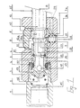
- FIG 1 we see a coupler according to the present invention in the state fully mated, the left side of the figure representing the upstream side where there is a source of fluid under pressure, and the right side representing the downstream side towards which the pressurized fluid flows following the complete coupling of the coupler.
- the female part includes a first socket 3, called external, which has on its upstream side a thread inside as well as a second socket 1 comprising on its downstream side an external thread which is screwed into the internal thread of the external sleeve forming a housing for a seal 4 which projects inward of the two sockets.
- the inner sleeve 1 has a shoulder 15 forming a seat for a spring 2.
- valve 5 Inside the outer sleeve and partially also inside the inner sleeve is located a valve 5 comprising a head portion 16 as well as a cylindrical part 17 which is closed on its upstream side by said head portion 16, said valve 5 being arranged to axially sliding inside an opening axial of the outer sleeve whose inner diameter is substantially equal to the outside diameter of the part cylindrical 17 of the valve 5 so as to allow guidance exact of the valve 5 during its axial movement inside of the outer sleeve 3 during the different stages coupling and uncoupling between male parts and female.
- the cylindrical part 17 At its upstream end the cylindrical part 17 comprises radial openings 18, and the head portion 16 of a side as well as the cylindrical part on the other side of these openings have a frustoconical surface 19 and a annular surface respectively which is formed by a polygonal generator 20, capable of marrying one of the two corresponding surfaces of the seal 4 during the valve opening or closing position respectively.
- Figure 1 shows the open position of the valve 5 where the "polygonal" surface is in contact with the joint sealing 4 so that the openings 18 are open and allow the passage of a fluid, under pressure or not, from the upstream side of the female part to inside the valve passing through the openings 18.
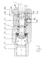
- Figures 2 and 3 show positions of the coupler in which the valve is closed, positions in which the frustoconical surface 19 of the head element 16 marries the frustoconical surface of the seal 4 so as to hermetically seal the part of the female part which located upstream of the valve.
- the cylindrical part 17 of the valve 5 has a bore interior with two sections with different diameters, the intersection of these two parts forming a shoulder followed by a circumferential groove in which is housed a seal 6 which is intended to seal the inside of the valve 5 and the inside of the male part 10 towards the bore of the outer sleeve when the complete coupling of the male part 10 inside of the female part.
- the outer sleeve 3 has a radial bore 21 of diameter greater than the diameter of its axial bore, and said radial bore houses a cylindrical lock which has for its part a radial bore 22 which is located in a more or less coaxial position with the axial bore of the outer sleeve 3, in order to allow or not the passage of the male part 10 through the radial bore 22 of the lock.
- the male part 10 has an insertion end 24 having an outer diameter substantially equal to inside diameter of the larger diameter part of the cylindrical part 17 of the valve 5 so that the end 24 of the male element 10 can be introduced in the cylindrical part 17 of the valve until it abuts the seal 6.
- this has a rib circumferential 14 accompanied by a frustoconical part 23 forming a ramp whose maximum diameter corresponds to outer diameter of the rib 14, and said rib 14 is followed downstream by a wide groove 8 which extends to a thick part 25 of the male part 10, a tapered ramp being formed between the groove 8 and part 25.
- the radial bore 22 of the latch 7 has a first tooth 12 located on the side of an accessible end of the lock 7, while a second tooth 11 is located diametrically opposite the first tooth 12 near one end inside 7a of latch 7.
- a spring 9 rests on a shoulder 26 of the bore radial 21 of the outer sleeve 3, to stress the latch 7 in a rest position as illustrated in figure 1.
- the tooth 12 is at a radial distance from axis A of the coupler, distance which gives off the tooth 12 of the axial passage of the rib 14 of the part male 10.
- the larger diameter portion of the cylindrical portion 17 of the valve 5 comprises downstream of the seal 6 of the radial openings 27 which allow, in the position closed valve 5 as shown in Figures 2 and 3, the communication between the interior of the cylindrical part 17 and the radial bore 21 of the latch 7, said radial bore 21 further comprising an opening 28 in the vicinity of the shoulder 26 which serves as a seat for the spring 9, so that a residual pressure of the fluid contained at inside the cylindrical part 17 of the valve 5 and at inside the male part 10 as well as in all downstream pipes may escape to the outside during a operation phase of the coupler which is illustrated in FIG. 2.
- Such a depression of the latch 7 therefore allows a retreat of the male part under the pressure of the internal fluid or simply by manual traction if the internal fluid is not under pressure, up to an axial position in which the shoulder 14a of the rib 14 abuts against the shoulder 12a of tooth 12, position in which the male part 10 is maintained as long as the lock 7 stays down.
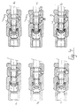
- Figures 4 show a series of coupling steps and for uncoupling the coupler illustrated in FIGS. 1 to 3, the position a) showing the phase just before mating complete, phase in which the valve is still closed and the lock is in the rest position.
- valve In position c), the valve is open and the male part is locked in its fully coupled position by the second tooth which has just clicked behind the rib circumferential.
- This spirit of the invention lies in the principle of providing a complete uncoupling of a coupler by a single pushing on the latch and releasing it, so that depressing said latch allows partial release between the male and female parts of the coupler, while the next release of the bolt allows complete release of the two rooms.
- the first phase of partial release produces a intermediate positioning of the male part in the part female during which the pressure of any downstream fluid of the valve of the female part can quickly and surely escape before the second phase of disengagement complete can be performed.
Landscapes
- Engineering & Computer Science (AREA)
- General Engineering & Computer Science (AREA)
- Mechanical Engineering (AREA)
- Quick-Acting Or Multi-Walled Pipe Joints (AREA)
Claims (9)
- Schnellkupplung mit einem Steckerteil (10) und einem Buchsenteil (1, 3), in das das Steckerteil eingeschoben werden kann, wobei das Buchsenteil (1, 3) mit einem Sperrring (7) ausgestattet ist, der zwei Greifzähne (11, 12) aufweist, die zu beiden Seiten des Steckerteils angeordnet sind, um mit Greiforganen (14) des Steckerteils so zusammenzuwirken, dass ein Entkoppeln des Steckerteils vom Buchsenteil in zwei Phasen erfolgt, die einem einzigen Niederdrücken und einem einzigen Loslassen des benannten Sperrrings (7) entsprechen, wobei das benannte Buchsenteil (1, 3) ein Verschlussventil (5) umfasst, das in eine schliessende Stellung gedrückt wird, wenn Stecker- und Buchsenteil entkoppelt sind, aber durch den Schub des Steckerteils (10) geöffnet wird, wenn dieses in das Buchsenteil (1, 3) eingekoppelt wird, wobei das Verschlussventil (5) einen hohlzylindrischen Abschnitt (17) umfasst und die beiden Zähne (11, 12) axial genügend weit voneinander beabstandet sind, um während eines einzigen Niederdrückens des Sperrrings (7) einen Rückzug des Steckerteils (10) bezüglich des Buchsenteils (1, 3) zum Schliessen des Ventils (7) zu ermöglichen, dadurch gekennzeichnet, dass der hohlzylindrische Abschnitt (17) des Verschlussventils (5) einen vorderen Abschnitt (24) des Steckerteils (10) aufnimmt und eine Dichtung (6) enthält, die dazu bestimmt ist, die Kupplung zwischen dem Ventil (5) und dem Steckerteil (10) dicht zu gestalten, wobei dieser zylindrische Abschnitt (17) strömungsabwärts von der benannten Dichtung (6) mehrere radiale Öffnungen (27) hat, und dass der Rückzug des Steckerteils (10) bezüglich des Buchsenteils (1, 3) während eines einzigen Niederdrückens des Sperrrings (7) zum Schliessen des Ventils die Öffnungen (27) freigibt, um das Entweichen des unter Druck stehenden Fluids strömungsabwärts vom geschlossenen Ventil (5) nach aussen zu gestatten, während das Steckerteil (10) noch im Buchsenteil (1, 3) zurückgehalten wird, wobei das Loslassen des Sperrrings (7) die Abkopplung des Steckerteils (10) vom Sperrring (7) nach sich zieht.
- Kupplung gemäss Anspruch 1, dadurch gekennzeichnet, dass das Buchsenteil (1, 3) eine zweite Dichtung (4) umfasst, die dazu bestimmt ist, das Innere des Buchsenteils (1, 3) nach aussen hin abzudichten, wenn sich das Ventil (5) in einer offenen Stellung befindet, und zusätzlich das benannte Ventil (5) zu dichten, wenn es sich in seiner geschlossenen Stellung befindet.
- Kupplung gemäss einem der Ansprüche 1 oder 2, dadurch gekennzeichnet, dass das Ventil (5) einen Hohlzylinder mit einem geschlossenen Kopfabschnitt (16) und mit dem benannten zylindrischen Abschnitt (17) umfasst, wobei der benannte zylindrische Abschnitt (17) mit Löchern (18) versehen ist, die durch die benannte zweite Dichtung (4) verschlossen werden können, wenn das Ventil geschlossen ist, und wobei der benannte zylindrische Abschnitt (17) zwei Abschnitte einer axialen Bohrung des benannten zylindrischen Abschnitts mit verschiedenen Durchmessern umfasst, die zwischen sich einen Vorsprung und eine periphere Rille bilden, die als Sitz für die benannte Dichtung (6) dient, während der Abschnitt grösseren Durchmessers des zylindrischen Abschnitts des Ventils die radialen Öffnungen (27) strömungsabwärts von der benannten Dichtung (6) aufweist und einen vorderen Abschnitt (24) des Steckerteils (10) aufnimmt.
- Kupplung gemäss Anspruch 3, dadurch gekennzeichnet, dass das Buchsenteil (1, 3) eine Feder (2) umfasst, die das Ventil (5) in seine geschlossene Stellung drückt.
- Kupplung gemäss Ansprüchen 3 oder 4, dadurch gekennzeichnet, dass der Kopfabschnitt (16) des Ventils (5) eine kegelstumpfartige Fläche (19) aufweist, die sich an eine entsprechende kegelstumpfartige Fläche der benannten anderen Dichtung (4) anschmiegen kann, wenn das Ventil (5) geschlossen ist.
- Kupplung gemäss einem beliebigen der Ansprüche 1 bis 5, dadurch gekennzeichnet, dass das Buchsenteil (1, 3) an einem Punkt strömungsabwärts vom Ventil (5) eine radiale Bohrung (21) aufweist, die den Sperrring (7) aufnimmt, der einen Zylinder umfasst, der von einem radialen Loch (22) für den Durchtritt des Steckerteils (10) durchbohrt wird.
- Kupplung gemäss Anspruch 6, dadurch gekennzeichnet, dass das radiale Loch (22) des Sperrrings (7) Vorsprünge zum Inneren des Loches hin aufweist, die Verriegelungszähne (11, 10) bilden.
- Kupplung gemäss Anspruch 7, dadurch gekennzeichnet, dass die radiale Bohrung (21) des Buchsenabschnitts (1, 3) auf der einen Seite des Buchsenabschnitts (1, 3) in eine genügend grosse Öffnung für den Durchtritt des Sperrrings (7) mündet und sich auf der entgegengesetzten Seite der benannten radialen Bohrung (21) des Buchsenabschnitts (1, 3) eine kleinere Öffnung (28) befindet, die mit den radialen Öffnungen (27) des Abschnitts grösseren Durchmessers des zylindrischen Abschnitts (17) des Ventils (5) in Verbindung steht, um das Entweichen des restlichen Fluids strömungsabwärts vom Ventil zur Aussenseite des Buchsenabschnitts zu gestatten, bevor Steckerabschnitt (10) und Buchsenabschnitt (1, 3) völlig entkoppelt sind.
- Kupplung gemäss Anspruch 8, dadurch gekennzeichnet, dass sie eine in den vorderen Abschnitt des Buchsenteils eingelassene Öffnung (29) oder irgend eine andere Öffnung umfasst, die die Entspannung des Fluids strömungsabwärts vom Ventil (5) gestattet.
Applications Claiming Priority (2)
| Application Number | Priority Date | Filing Date | Title |
|---|---|---|---|
| FR9404783 | 1994-04-21 | ||
| FR9404783A FR2719105B1 (fr) | 1994-04-21 | 1994-04-21 | Coupleur rapide pour conduit sous pression à désaccouplement contrôlé. |
Publications (2)
| Publication Number | Publication Date |
|---|---|
| EP0678697A1 EP0678697A1 (de) | 1995-10-25 |
| EP0678697B1 true EP0678697B1 (de) | 1998-06-24 |
Family
ID=9462358
Family Applications (1)
| Application Number | Title | Priority Date | Filing Date |
|---|---|---|---|
| EP95105746A Expired - Lifetime EP0678697B1 (de) | 1994-04-21 | 1995-04-18 | Schnellkupplung zum kontrollierten Trennen von unter Druck stehenden Rohren |
Country Status (6)
| Country | Link |
|---|---|
| US (1) | US5535985A (de) |
| EP (1) | EP0678697B1 (de) |
| CA (1) | CA2147409C (de) |
| DE (1) | DE69503088T2 (de) |
| ES (1) | ES2120655T3 (de) |
| FR (1) | FR2719105B1 (de) |
Families Citing this family (31)
| Publication number | Priority date | Publication date | Assignee | Title |
|---|---|---|---|---|
| FR2740197B1 (fr) * | 1995-10-20 | 1997-12-26 | Yto | Coupleur rapide a desaccouplement a deux phases |
| SE506405C2 (sv) * | 1996-03-22 | 1997-12-15 | Nyberg Bo Erik | Snabbkoppling med tryckavlastning för säkert lösgörande |
| FR2778575B1 (fr) * | 1998-05-12 | 2000-07-28 | Intertechnique Sa | Equipement de protection respiratoire a mise en place rapide |
| US6237891B1 (en) * | 1999-09-08 | 2001-05-29 | Burnswick Corporation | Adaptor for use of alternate gas fuel |
| DE10011724C1 (de) * | 2000-03-10 | 2001-04-26 | Fresenius Medical Care De Gmbh | Konnektor mit innerem Verschiebeelement |
| US6702254B2 (en) * | 2001-03-22 | 2004-03-09 | Hoke, Inc. | Universal safety coupler |
| FR2835585B1 (fr) * | 2002-02-04 | 2004-03-05 | Staubli Sa Ets | Raccord rapide pour la jonction amovible de deux canalisations |
| FR2847330A1 (fr) * | 2002-11-19 | 2004-05-21 | Staubli Sa Ets | Raccord rapide pour la jonction amovible de deux canalisations |
| ITMI20022716A1 (it) * | 2002-12-20 | 2004-06-21 | Faster Spa | Innesto rapido con possibilita' di aggancio, rispettivamente |
| US6902144B2 (en) * | 2003-01-10 | 2005-06-07 | Colder Products Company | Connector apparatus with seal protector and method of the same |
| US7080665B2 (en) * | 2003-09-09 | 2006-07-25 | Colder Products Company | Connector apparatus and method of coupling bioprocessor equipment to a media source |
| FR2861159B1 (fr) * | 2003-10-17 | 2007-05-11 | Staubli Sa Ets | Raccord rapide pour la jonction amovible de deux canalisations et utilisation d'un tel raccord |
| TWI257202B (en) | 2005-05-04 | 2006-06-21 | Realtek Semiconductor Corp | Filter of tunable bandwidth |
| US7102441B2 (en) * | 2003-12-31 | 2006-09-05 | Realtek Semiconductor Corp. | Variable gain amplifying circuit |
| FR2865259B1 (fr) * | 2004-01-20 | 2006-04-21 | Staubli Sa Ets | Raccord rapide et procede de desacouplement des elements male et femelle d'un tel raccord |
| FR2865522B1 (fr) * | 2004-01-27 | 2006-03-03 | Staubli Sa Ets | Element femelle de raccord, raccord rapide et installation de remplissage comprenant un tel element femelle |
| FR2882803B1 (fr) * | 2005-03-02 | 2007-04-20 | Staubli Faverges Sca | Raccord rapide pour la jonction de deux canalisations d'acheminement d'un gaz sous pression |
| US20090143723A1 (en) * | 2007-11-29 | 2009-06-04 | Baxter International Inc. | Flow control device for peritoneal dialysis |
| CN107035930B (zh) | 2011-03-21 | 2020-03-17 | 工程控制国际有限公司 | 具有排气止挡件的快速连接联接器 |
| FR2985554B1 (fr) * | 2012-01-10 | 2014-02-14 | Wichard | Dispositif de connexion mecanique pour relier une charge a un support |
| JP5926809B2 (ja) * | 2012-09-28 | 2016-05-25 | 日東工器株式会社 | 安全機能を有する雌型継手 |
| WO2014153079A1 (en) * | 2013-03-14 | 2014-09-25 | Macro Technologies, Llc | Rapid-connect coupler with vent-holes |
| JP6372646B2 (ja) * | 2013-11-26 | 2018-08-15 | ダイセン株式会社 | ソケットおよびそれを有する管継手 |
| US9897239B2 (en) | 2015-04-27 | 2018-02-20 | Engineered Controls International, Llc | Rapid-connect coupler with vent stop |
| US10386017B2 (en) | 2015-12-03 | 2019-08-20 | Engineered Controls International, Llc | Low emission nozzles and receptacles |
| CN111601997B (zh) * | 2017-09-13 | 2022-08-09 | 可得制品公司 | 流体处理部件 |
| US20190086011A1 (en) * | 2017-09-19 | 2019-03-21 | Campbell Hausfeld, Llc | Push-button quick-connect coupler including a pressure gauge |
| EP3545808A1 (de) * | 2018-03-26 | 2019-10-02 | HILTI Aktiengesellschaft | Schlauchkupplungssystem für einen staubsauger |
| US11326729B2 (en) | 2019-01-24 | 2022-05-10 | Daisen Co., Ltd. | Socket and pipe joint including the same |
| US11236851B1 (en) * | 2021-04-06 | 2022-02-01 | Trinity Bay Equipment Holdings, LLC | Quick connect pipe fitting systems and methods |
| US12498068B2 (en) * | 2024-02-06 | 2025-12-16 | Hsiu-Hsiung LIU | Quick release connector with safety button |
Family Cites Families (7)
| Publication number | Priority date | Publication date | Assignee | Title |
|---|---|---|---|---|
| US2092116A (en) * | 1935-11-07 | 1937-09-07 | Fred E Hansen | Hose coupling |
| FR1503989A (fr) * | 1966-10-10 | 1967-12-01 | Staubli Freres & Cie | Dispositif de raccord rapide pour canalisations et applications analogues |
| FR2166770A5 (de) * | 1972-01-03 | 1973-08-17 | Staubli Ets France | |
| FR2511115B1 (fr) * | 1981-08-07 | 1985-12-27 | Staubli Sa Ets | Perfectionnements aux raccords rapides pour la jonction amovible des canalisations |
| FR2514855A1 (fr) * | 1981-10-20 | 1983-04-22 | Staubli Sa Ets | Perfectionnements aux raccords rapides pour la jonction amovible des canalisations |
| US4863201A (en) * | 1986-11-03 | 1989-09-05 | Hall Surgical Division Of Zimmer, Inc. | Coupling assembly |
| US4858648A (en) * | 1987-08-28 | 1989-08-22 | Smith Iii Robert E | Self-flushing hydraulic coupling |
-
1994
- 1994-04-21 FR FR9404783A patent/FR2719105B1/fr not_active Expired - Lifetime
-
1995
- 1995-04-18 DE DE69503088T patent/DE69503088T2/de not_active Expired - Fee Related
- 1995-04-18 ES ES95105746T patent/ES2120655T3/es not_active Expired - Lifetime
- 1995-04-18 EP EP95105746A patent/EP0678697B1/de not_active Expired - Lifetime
- 1995-04-19 US US08/425,148 patent/US5535985A/en not_active Expired - Fee Related
- 1995-04-20 CA CA002147409A patent/CA2147409C/en not_active Expired - Fee Related
Also Published As
| Publication number | Publication date |
|---|---|
| CA2147409C (en) | 2006-06-27 |
| EP0678697A1 (de) | 1995-10-25 |
| FR2719105A1 (fr) | 1995-10-27 |
| DE69503088D1 (de) | 1998-07-30 |
| CA2147409A1 (en) | 1995-10-22 |
| DE69503088T2 (de) | 1998-12-17 |
| FR2719105B1 (fr) | 1996-05-31 |
| US5535985A (en) | 1996-07-16 |
| ES2120655T3 (es) | 1998-11-01 |
Similar Documents
| Publication | Publication Date | Title |
|---|---|---|
| EP0799396B1 (de) | Schnellverbindung mit entkupplung in zwei stufen | |
| EP0678697A1 (de) | Schnellkupplung zum kontrollierten Trennen von unter Druck stehenden Rohren | |
| EP2439440B1 (de) | Anschlussvorrichtung mit Verriegelung durch Gewindegriffe, und Anschluss, der eine solche Vorrichtung enthält | |
| EP3339710B1 (de) | Anschlussbuchse zum anschliessen eines entsprechendes steckerelements, und anschluss, der eine solche buchse umfasst | |
| EP0715111B1 (de) | Schnellverbindungsvorrichtung zum Kuppeln eines Rohres auf einem starren Ansatzstück | |
| EP0077743B1 (de) | Schnellkupplungen für lösbare Rohrverbindungen von Rohrleitungen | |
| EP0960300B1 (de) | Vorrichtung zum schnellen verbinden eines rohres mit einem starren element mit trennsicherungsring und zustandsanzeiger | |
| EP1219885A1 (de) | Steckdosenelement und Schnellkupplung und Vorrichtung die ein solches Element enthält | |
| EP2878872B1 (de) | Schnellanschluss zur lösbaren Verbindung von zwei Rohren | |
| FR2528148A1 (fr) | Dispositif d'accouplement autoverrouillable | |
| FR2836203A1 (fr) | Raccord destine a relier des conduites hydrauliques | |
| EP2587109B1 (de) | Anschlussvorrichtung | |
| EP3553363B1 (de) | Kupplungselement und kupplungsvorrichtung mit solchem kupplungselement | |
| EP4124788A1 (de) | Steckanschlusselement eines fluidanschlusses und ein solches steckelement umfassender fluidanschluss | |
| EP1343995B1 (de) | Schnellkupplung mit verbindungsanzeige | |
| FR2511115A1 (fr) | Perfectionnements aux raccords rapides pour la jonction amovible des canalisations | |
| EP2101097A1 (de) | Anschlussvorrichtung für den Transfer eines Fluids, Kreislauf, der diese Vorrichtung umfasst, und entsprechendes Montage-/Demontageverfahren | |
| FR2545908A1 (fr) | Raccord rapide de securite pour la jonction amovible des canalisations | |
| FR2636715A1 (fr) | Raccord a tuyaux | |
| FR2724710A1 (fr) | Raccord rapide a desaccouplement controle | |
| FR3057049B1 (fr) | Raccord hydraulique auto-obturant. | |
| BE1005841A3 (fr) | Coupleur de securite pour robinet de recipient de fluide sous pression. | |
| EP3999765B1 (de) | Kompakte und demontierbare fluidverbindungsvorrichtung | |
| EP1580478A1 (de) | Verriegelbares/Entriegelbares Rohrfitting | |
| FR2527741A1 (fr) | Perfectionnements aux raccords rapide pour la jonction amovible des canalisations |
Legal Events
| Date | Code | Title | Description |
|---|---|---|---|
| PUAI | Public reference made under article 153(3) epc to a published international application that has entered the european phase |
Free format text: ORIGINAL CODE: 0009012 |
|
| 17P | Request for examination filed |
Effective date: 19950428 |
|
| AK | Designated contracting states |
Kind code of ref document: A1 Designated state(s): CH DE ES FR GB IT LI SE |
|
| RIN1 | Information on inventor provided before grant (corrected) |
Inventor name: LARBOUISSON, PATRICK, C/O SOCIETE Y.T.O. |
|
| 17Q | First examination report despatched |
Effective date: 19970425 |
|
| GRAG | Despatch of communication of intention to grant |
Free format text: ORIGINAL CODE: EPIDOS AGRA |
|
| GRAG | Despatch of communication of intention to grant |
Free format text: ORIGINAL CODE: EPIDOS AGRA |
|
| GRAG | Despatch of communication of intention to grant |
Free format text: ORIGINAL CODE: EPIDOS AGRA |
|
| GRAH | Despatch of communication of intention to grant a patent |
Free format text: ORIGINAL CODE: EPIDOS IGRA |
|
| GRAH | Despatch of communication of intention to grant a patent |
Free format text: ORIGINAL CODE: EPIDOS IGRA |
|
| GRAA | (expected) grant |
Free format text: ORIGINAL CODE: 0009210 |
|
| AK | Designated contracting states |
Kind code of ref document: B1 Designated state(s): CH DE ES FR GB IT LI SE |
|
| REG | Reference to a national code |
Ref country code: CH Ref legal event code: EP |
|
| REF | Corresponds to: |
Ref document number: 69503088 Country of ref document: DE Date of ref document: 19980730 |
|
| GBT | Gb: translation of ep patent filed (gb section 77(6)(a)/1977) |
Effective date: 19980909 |
|
| REG | Reference to a national code |
Ref country code: ES Ref legal event code: FG2A Ref document number: 2120655 Country of ref document: ES Kind code of ref document: T3 |
|
| PLBE | No opposition filed within time limit |
Free format text: ORIGINAL CODE: 0009261 |
|
| STAA | Information on the status of an ep patent application or granted ep patent |
Free format text: STATUS: NO OPPOSITION FILED WITHIN TIME LIMIT |
|
| 26N | No opposition filed | ||
| REG | Reference to a national code |
Ref country code: GB Ref legal event code: IF02 |
|
| REG | Reference to a national code |
Ref country code: CH Ref legal event code: PL |
|
| REG | Reference to a national code |
Ref country code: CH Ref legal event code: NV Representative=s name: NOVAGRAAF INTERNATIONAL SA Ref country code: CH Ref legal event code: AEN Free format text: POURSUITE DE LA PROCEDURE ACCORDEE |
|
| PGFP | Annual fee paid to national office [announced via postgrant information from national office to epo] |
Ref country code: DE Payment date: 20060421 Year of fee payment: 12 |
|
| PGFP | Annual fee paid to national office [announced via postgrant information from national office to epo] |
Ref country code: SE Payment date: 20060424 Year of fee payment: 12 Ref country code: GB Payment date: 20060424 Year of fee payment: 12 |
|
| PGFP | Annual fee paid to national office [announced via postgrant information from national office to epo] |
Ref country code: FR Payment date: 20060425 Year of fee payment: 12 |
|
| PGFP | Annual fee paid to national office [announced via postgrant information from national office to epo] |
Ref country code: CH Payment date: 20060427 Year of fee payment: 12 |
|
| PGFP | Annual fee paid to national office [announced via postgrant information from national office to epo] |
Ref country code: ES Payment date: 20060428 Year of fee payment: 12 |
|
| PGFP | Annual fee paid to national office [announced via postgrant information from national office to epo] |
Ref country code: IT Payment date: 20060430 Year of fee payment: 12 |
|
| REG | Reference to a national code |
Ref country code: CH Ref legal event code: PL |
|
| GBPC | Gb: european patent ceased through non-payment of renewal fee |
Effective date: 20070418 |
|
| PG25 | Lapsed in a contracting state [announced via postgrant information from national office to epo] |
Ref country code: DE Free format text: LAPSE BECAUSE OF NON-PAYMENT OF DUE FEES Effective date: 20071101 |
|
| PG25 | Lapsed in a contracting state [announced via postgrant information from national office to epo] |
Ref country code: CH Free format text: LAPSE BECAUSE OF NON-PAYMENT OF DUE FEES Effective date: 20070430 Ref country code: LI Free format text: LAPSE BECAUSE OF NON-PAYMENT OF DUE FEES Effective date: 20070430 |
|
| PG25 | Lapsed in a contracting state [announced via postgrant information from national office to epo] |
Ref country code: GB Free format text: LAPSE BECAUSE OF NON-PAYMENT OF DUE FEES Effective date: 20070418 |
|
| PG25 | Lapsed in a contracting state [announced via postgrant information from national office to epo] |
Ref country code: SE Free format text: LAPSE BECAUSE OF NON-PAYMENT OF DUE FEES Effective date: 20070419 |
|
| REG | Reference to a national code |
Ref country code: ES Ref legal event code: FD2A Effective date: 20070419 |
|
| PG25 | Lapsed in a contracting state [announced via postgrant information from national office to epo] |
Ref country code: FR Free format text: LAPSE BECAUSE OF NON-PAYMENT OF DUE FEES Effective date: 20070430 |
|
| PG25 | Lapsed in a contracting state [announced via postgrant information from national office to epo] |
Ref country code: ES Free format text: LAPSE BECAUSE OF NON-PAYMENT OF DUE FEES Effective date: 20070419 |
|
| PG25 | Lapsed in a contracting state [announced via postgrant information from national office to epo] |
Ref country code: IT Free format text: LAPSE BECAUSE OF NON-PAYMENT OF DUE FEES Effective date: 20070418 |