EP0678706B1 - Armature d'éclairage encastrée au plafond - Google Patents
Armature d'éclairage encastrée au plafond Download PDFInfo
- Publication number
- EP0678706B1 EP0678706B1 EP95105574A EP95105574A EP0678706B1 EP 0678706 B1 EP0678706 B1 EP 0678706B1 EP 95105574 A EP95105574 A EP 95105574A EP 95105574 A EP95105574 A EP 95105574A EP 0678706 B1 EP0678706 B1 EP 0678706B1
- Authority
- EP
- European Patent Office
- Prior art keywords
- ceiling
- accessory support
- lighting fixture
- fastened
- recessed lighting
- Prior art date
- Legal status (The legal status is an assumption and is not a legal conclusion. Google has not performed a legal analysis and makes no representation as to the accuracy of the status listed.)
- Expired - Lifetime
Links
Images

Classifications
-
- F—MECHANICAL ENGINEERING; LIGHTING; HEATING; WEAPONS; BLASTING
- F21—LIGHTING
- F21V—FUNCTIONAL FEATURES OR DETAILS OF LIGHTING DEVICES OR SYSTEMS THEREOF; STRUCTURAL COMBINATIONS OF LIGHTING DEVICES WITH OTHER ARTICLES, NOT OTHERWISE PROVIDED FOR
- F21V23/00—Arrangement of electric circuit elements in or on lighting devices
- F21V23/02—Arrangement of electric circuit elements in or on lighting devices the elements being transformers, impedances or power supply units, e.g. a transformer with a rectifier
- F21V23/026—Fastening of transformers or ballasts
-
- F—MECHANICAL ENGINEERING; LIGHTING; HEATING; WEAPONS; BLASTING
- F21—LIGHTING
- F21S—NON-PORTABLE LIGHTING DEVICES; SYSTEMS THEREOF; VEHICLE LIGHTING DEVICES SPECIALLY ADAPTED FOR VEHICLE EXTERIORS
- F21S8/00—Lighting devices intended for fixed installation
- F21S8/02—Lighting devices intended for fixed installation of recess-mounted type, e.g. downlighters
-
- F—MECHANICAL ENGINEERING; LIGHTING; HEATING; WEAPONS; BLASTING
- F21—LIGHTING
- F21V—FUNCTIONAL FEATURES OR DETAILS OF LIGHTING DEVICES OR SYSTEMS THEREOF; STRUCTURAL COMBINATIONS OF LIGHTING DEVICES WITH OTHER ARTICLES, NOT OTHERWISE PROVIDED FOR
- F21V21/00—Supporting, suspending, or attaching arrangements for lighting devices; Hand grips
- F21V21/02—Wall, ceiling, or floor bases; Fixing pendants or arms to the bases
- F21V21/04—Recessed bases
Definitions
- the present invention relates to a recessed ceiling light according to the preamble of claim 1.
- the upper part of the support frame is closed on the ceiling.
- the inside of the luminaire is attached to the support frame protruding reflector mounts, lamp holders and Connections attached.
- Others Installation elements such as Ballasts, Terminals or the like mostly on the outside of the Attached to the top or on the outside of one of the arms.
- the support frame is a one-piece cast aluminum part, prepares the attachment of the aforementioned lighting parts on Support frame difficulties. So far, grits have been required for this be made in the casting, so that afterwards in several Work steps for the attachment of each Luminaire parts required holes must be made could, depending on the type of luminaire a different Number of holes in different places was necessary. So far, it was also not sensible to manufacture and To rationalize assembly processes in that one for different luminaire types different from the start Support frame provided since the support frame are cast and this would involve considerable tool costs. The The difficulty lay in the relatively complex mechanical processing of the cast supporting frame.
- a light emitter which has a base frame on which a lamp holder is slidably mounted along struts.
- the reflector consists of a reflector part fixed to the frame and a head mirror which can be moved therein and forms the rear end of the reflector.
- the head mirror is attached to the lamp holder and can be moved together with it.
- the lamp holder is releasably clamped to the lamp holder and carries a printed circuit board on the back with the components required for lamp operation.
- the light emitter has a base frame which is attached to the wall through the wall opening of a wall.
- the base frame consists of an annular frame that can be used with play in the wall opening and with a support flange on the front of the wall opening supports. From the back of the frame stand rigidly with this connected round rods to the rear, which the Lamp holder with lamp holder and the required electrical components such as ballasts carry.
- the distance between the lamp holder compared to the base frame is a change in Beam characteristics of the light emitter possible. Disadvantageous in this embodiment is the high manufacturing technology Expenditure. A change in the illuminant would be the State of the art previously described The effort to change the lamp holder entail.
- the present invention is therefore based on the object a recessed ceiling light of the type mentioned create where the support frame for different designed luminaire types is suitable and elaborate Processing operations on the support frame in connection with the Fastening of the lamp parts to be attached to it is not necessary can.
- An object of the invention provides the solution to this problem Recessed ceiling light of the type mentioned with the characteristic Features of the main claim.
- the support frame consists of a one-piece Cast part made of aluminum, the arms having recesses, the appropriate means for attaching the support frame in the Can accommodate ceiling opening and being the supporting frame radially inward cast on the upper part Has mounting tabs, the fasteners for Attachment of the equipment carrier can record.
- the Ceiling lamp has the advantage that regardless of the type of the illuminant and the installation elements, and thus the equipment rack, a similar support frame and unchanged mounting brackets can be used. Draw changes to illuminants and installation elements therefore only changes to the equipment carrier itself.
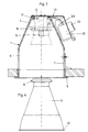
- the Recessed ceiling light on a support frame 1 which is preferably is made from a one-piece aluminum casting and a truncated cone 2, two arms 3 and an annular Includes Appendix 4 for a ceiling opening.
- Appendix 4 for a ceiling opening.
- On the outer edge of the ring-shaped system 4 is a horizontal ceiling ring 5 formed after installing the lamp in the ceiling of a room rests on the ceiling.
- the parallel Section of the arms 3 has recesses 7, which for Attachment of the support frame 1 in a ceiling by means of suitable fasteners can be used.
- the parallel section of the arms 3 is preferably on provided on the outside with sawtooth profiling 6, to a secure connection of the support frame 1 with the To ensure fasteners (see Fig. 3).
- FIG. 3 is the installation of a device carrier 13 for a Compact fluorescent lamp shown.
- the equipment rack 13 is formed from a piece of sheet metal, and has a circular shape Plate 14 on the top opening of the truncated cone 2 covers.
- On this circular plate 14 of the Device carrier 13 are two clips made of spring steel 15 attached, which serve as reflector brackets.
- the Clips 15 are on opposite sides in the edge area the circular plate 14 attached and protrude through the Truncated cone 2 through.
- the clasps 15 include one lower, straight or slightly inclined towards the mantle Section, an adjoining towards the Truncated cone axis curved section and an upper Section that again towards the coat resigns.
- By in the direction of the truncated cone axis extending section of the clips 15 are resilient notches 16 formed behind which an annular retaining bead 17th can snap into place at the rear end of the support frame 1 insertable reflector 9 is formed.
- the Support ring 10 fits snugly in the annular paragraph 8 of the Ceiling mounting ring, so that the reflector 9 is not further can move into the support frame 1.
- the Support ring 10 and the annular shoulder 8 approximately the same thickness to create a pleasant exterior To ensure the appearance of the recessed ceiling light.
- a lamp holder 18 is mounted, the feed lines 19 through a recess 20 in the truncated cone 2 from the Inside of the truncated cone 2 are led out (Fig. 3).
- the device carrier 13 also has one from the same sheet metal shaped section that along with one of the arms 3 has a housing-like receptacle 21 for it assembled ballast 22 forms.
- the feed lines 19 can of the ballast elements 22 on the outside, in the area the ballast elements 22, mounted on the equipment rack 13 Terminals 23 are forwarded.
- the equipment carrier 13 is only in the three Fastening tabs 11 engaging screws with the Support frame 1 connected and can be used depending on Lamp type selected and exchanged quickly.
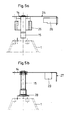
- FIGS. 5a and 5b in which alternative equipment carrier 24, 27 for the installation of others Lamp types are shown.
- FIGS. 5a and 5b in which alternative equipment carrier 24, 27 for the installation of others Lamp types are shown.
- Figure 5a is a Device carrier 24 shown for Metal halide lamps, High pressure metal halide lamps and High pressure sodium vapor lamps is suitable.
- the equipment rack 24 also has a circular plate plate 14, on the inside of which a lamp holder 25 and clips 15 are attached.
- the housing-like receptacle 21 of the ballast 22 and the terminals 23 of the Device carrier 13 (FIG. 3) is on the device carrier 24 Connector 26 attached to the supply unit.
- a device carrier 27 which for Low-voltage halogen lamps is suitable.
- On the inside the circular plate 14 of the device carrier 27 are one Lamp holder 28 and clips 15 attached.
- the connector 26 of the device carrier 25 has the Equipment carrier 27 on a terminal 29.
Landscapes
- Engineering & Computer Science (AREA)
- General Engineering & Computer Science (AREA)
- Power Engineering (AREA)
- Fastening Of Light Sources Or Lamp Holders (AREA)
- Light Guides In General And Applications Therefor (AREA)
Claims (7)
- Armature d'éclairage encastrée dans le plafond avec un châssis de support (1) et avec des éléments d'éclairage (15, 16) et des éléments d'installation (18, 19, 22, 23, 25, 26, 28, 29) à fixer à ce châssis de support (1), où le châssis de support (1) présente une partie supérieure (2) et une partie inférieure avec des surfaces d'application de forme annulaire (4, 5) pour une ouverture dans le plafond, les deux parties étant reliées l'une à l'autre par deux bras (3), où la partie supérieure présente la forme d'une enveloppe tronconique ou d'une enveloppe cylindrique avec une ouverture sensiblement de forme circulaire ouverte côté plafond, ouverture dans laquelle depuis le haut peut être introduite un support d'équipement (13, 24, 27), auquel peuvent être fixés les éléments d'éclairage (15, 16) et les éléments d'installation (18, 19, 22, 23, 25, 26, 28, 29),
caractérisée
en ce que le châssis de support (1) est constitué par une seule pièce moulée en aluminium,
en ce que les bras (3) présentent des évidements (7), qui peuvent recevoir les moyens appropriés pour la fixation du châssis de support dans l'ouverture du plafond, et en ce que le châssis de support (1) présente des pattes de fixation (11) orientées radialement vers l'intérieur et moulées en une pièce avec la partie supérieure (2), pattes de fixation qui peuvent recevoir les éléments de fixation pour la fixation du support d'équipement (13, 24, 27). - Armature d'éclairage encastrée dans le plafond suivant la revendication 1, caractérisée en ce que les éléments d'éclairage fixés au support d'équipement (13, 24, 27) comprennent deux agrafes (15) avec moyens d'encliquetage (16), les agrafes (15) étant fixées à des côtés diamétralement opposé du support d'équipement (13, 24, 27) et s'engageant dans la partie supérieure (2), agrafes derrière lesquelles peut d'encliqueter un bourrelet de fixation (16) formée sur l'extrémité arrière du réflecteur (9).
- Armature d'éclairage encastrée dans le plafond suivant les revendications 1 et 2, caractérisée en ce que les pattes de fixation (11) formées sur le bord arrière de la partie supérieure (2) présentent des forures filetées, dans lesquelles peuvent être vissées mes vis pour la fixation du support d'équipement (13, 24, 27).
- Armature d'éclairage encastrée dans le plafond suivant les revendications 1 à 3, caractérisée en ce que les éléments d'installation fixés au support d'équipement (13) comprennent une douille pour lampe (18), des conducteurs d'alimentation (19), un élément de rhéostat (22) et une borne de connexion (23).
- Armature d'éclairage encastrée dans le plafond suivant les revendications 1 à 4, caractérisée en ce que le support d'équipement (13) est formé de manière telle que conjointement avec l'un des bras (3) il forme un logement (21) en forme de boítier pour l'élément de rhéostat (22).
- Armature d'éclairage encastrée dans le plafond suivant les revendications 1 à 3, caractérisée en ce que les éléments d'installation fixés au support d'équipement (24) comprennent une douille pour lampe (25), des conducteurs d'alimentation (19) et une fiche ce connexion (26) à l'unité d'alimentation.
- Armature d'éclairage encastrée dans le plafond suivant les revendications 1 à 3, caractérisée en ce que les éléments d'installation fixés au support d'équipement (24) comprennent une douille pour lampe (28), des conducteurs d'alimentation (19) et une borne de connexion (29).
Applications Claiming Priority (2)
| Application Number | Priority Date | Filing Date | Title |
|---|---|---|---|
| DE9406546U DE9406546U1 (de) | 1994-04-20 | 1994-04-20 | Deckeneinbauleuchte |
| DE9406546U | 1994-04-20 |
Publications (3)
| Publication Number | Publication Date |
|---|---|
| EP0678706A2 EP0678706A2 (fr) | 1995-10-25 |
| EP0678706A3 EP0678706A3 (fr) | 1995-11-08 |
| EP0678706B1 true EP0678706B1 (fr) | 1999-09-01 |
Family
ID=6907572
Family Applications (1)
| Application Number | Title | Priority Date | Filing Date |
|---|---|---|---|
| EP95105574A Expired - Lifetime EP0678706B1 (fr) | 1994-04-20 | 1995-04-13 | Armature d'éclairage encastrée au plafond |
Country Status (3)
| Country | Link |
|---|---|
| EP (1) | EP0678706B1 (fr) |
| AT (1) | ATE184089T1 (fr) |
| DE (2) | DE9406546U1 (fr) |
Families Citing this family (2)
| Publication number | Priority date | Publication date | Assignee | Title |
|---|---|---|---|---|
| DE29507478U1 (de) * | 1995-05-05 | 1995-07-06 | Jancik, Manfred, 59379 Selm | Deckeneinbauleuchte |
| DE102017104142A1 (de) | 2017-02-28 | 2018-08-30 | Osram Gmbh | Einbauleuchte, insbesondere für "Sealed For Life"-Leuchteneinsätze |
Family Cites Families (2)
| Publication number | Priority date | Publication date | Assignee | Title |
|---|---|---|---|---|
| DE4016531A1 (de) * | 1990-05-22 | 1991-11-28 | Trilux Lenze Gmbh & Co Kg | Lichtstrahler |
| FR2683617A1 (fr) * | 1991-11-08 | 1993-05-14 | Sedap Atelier | Appareil d'eclairage encastrable. |
-
1994
- 1994-04-20 DE DE9406546U patent/DE9406546U1/de not_active Expired - Lifetime
-
1995
- 1995-04-13 DE DE59506708T patent/DE59506708D1/de not_active Expired - Fee Related
- 1995-04-13 EP EP95105574A patent/EP0678706B1/fr not_active Expired - Lifetime
- 1995-04-13 AT AT95105574T patent/ATE184089T1/de active
Also Published As
| Publication number | Publication date |
|---|---|
| DE9406546U1 (de) | 1994-09-08 |
| EP0678706A2 (fr) | 1995-10-25 |
| EP0678706A3 (fr) | 1995-11-08 |
| ATE184089T1 (de) | 1999-09-15 |
| DE59506708D1 (de) | 1999-10-07 |
Similar Documents
| Publication | Publication Date | Title |
|---|---|---|
| EP2020561B1 (fr) | Luminaire | |
| EP0138746A1 (fr) | Armature avec source lumineuse linéaire accessoire | |
| DE69022913T2 (de) | Leuchte zum räumlichen Beleuchten. | |
| DE2503075C2 (de) | Fahrzeugscheinwerfer | |
| DE202013012464U1 (de) | Elektrische Leuchte | |
| EP0678706B1 (fr) | Armature d'éclairage encastrée au plafond | |
| DE9007795U1 (de) | Leuchte | |
| EP0453956A2 (fr) | Dispositif d'éclairage à faisceau asymétrique | |
| EP0551610A1 (fr) | Projecteur encastré | |
| EP1264137B1 (fr) | Lampe, en particulier lampe encastree | |
| DE29617628U1 (de) | Leuchtenanordnung | |
| EP0621442B1 (fr) | Armature d'éclairage encastrée dans un plafond | |
| DE4233930C2 (de) | Leuchte | |
| DE2209285A1 (de) | Leuchte, insbesondere leseleuchte in fahrzeugen | |
| EP0268759A2 (fr) | Phare du type projecteur pour véhicules | |
| EP0024580A1 (fr) | Lampe de signalisation ou feu de véhicule | |
| DE10227621A1 (de) | Leuchte | |
| DE4006769A1 (de) | Leuchte fuer kompakt-leuchtstofflampen | |
| DE102004058241A1 (de) | Leuchte | |
| DE2926934A1 (de) | Einbauleuchte | |
| DE4406029A1 (de) | Halogen-Schwenkleuchte | |
| EP1384640B1 (fr) | Feu de signalisation et agencement de lampe pour véhicules ferroviaires | |
| DE102016002072A1 (de) | Leuchte mit den Leuchtmitteln gegenüberliegenden Reflektoren, Bausatz und Reflektor hierfür | |
| DE20108980U1 (de) | Scheinwerfer | |
| AT400885B (de) | Leuchte, insbesondere decken- oder pendelleuchte |
Legal Events
| Date | Code | Title | Description |
|---|---|---|---|
| PUAI | Public reference made under article 153(3) epc to a published international application that has entered the european phase |
Free format text: ORIGINAL CODE: 0009012 |
|
| PUAL | Search report despatched |
Free format text: ORIGINAL CODE: 0009013 |
|
| AK | Designated contracting states |
Kind code of ref document: A2 Designated state(s): AT BE CH DE ES FR GB LI LU NL |
|
| AK | Designated contracting states |
Kind code of ref document: A3 Designated state(s): AT BE CH DE ES FR GB LI LU NL |
|
| 17P | Request for examination filed |
Effective date: 19960424 |
|
| 17Q | First examination report despatched |
Effective date: 19980514 |
|
| GRAG | Despatch of communication of intention to grant |
Free format text: ORIGINAL CODE: EPIDOS AGRA |
|
| GRAG | Despatch of communication of intention to grant |
Free format text: ORIGINAL CODE: EPIDOS AGRA |
|
| GRAH | Despatch of communication of intention to grant a patent |
Free format text: ORIGINAL CODE: EPIDOS IGRA |
|
| GRAH | Despatch of communication of intention to grant a patent |
Free format text: ORIGINAL CODE: EPIDOS IGRA |
|
| GRAA | (expected) grant |
Free format text: ORIGINAL CODE: 0009210 |
|
| AK | Designated contracting states |
Kind code of ref document: B1 Designated state(s): AT BE CH DE ES FR GB LI LU NL |
|
| PG25 | Lapsed in a contracting state [announced via postgrant information from national office to epo] |
Ref country code: NL Free format text: LAPSE BECAUSE OF FAILURE TO SUBMIT A TRANSLATION OF THE DESCRIPTION OR TO PAY THE FEE WITHIN THE PRESCRIBED TIME-LIMIT Effective date: 19990901 Ref country code: GB Free format text: LAPSE BECAUSE OF FAILURE TO SUBMIT A TRANSLATION OF THE DESCRIPTION OR TO PAY THE FEE WITHIN THE PRESCRIBED TIME-LIMIT Effective date: 19990901 Ref country code: FR Free format text: LAPSE BECAUSE OF FAILURE TO SUBMIT A TRANSLATION OF THE DESCRIPTION OR TO PAY THE FEE WITHIN THE PRESCRIBED TIME-LIMIT Effective date: 19990901 Ref country code: ES Free format text: THE PATENT HAS BEEN ANNULLED BY A DECISION OF A NATIONAL AUTHORITY Effective date: 19990901 |
|
| REF | Corresponds to: |
Ref document number: 184089 Country of ref document: AT Date of ref document: 19990915 Kind code of ref document: T |
|
| REG | Reference to a national code |
Ref country code: CH Ref legal event code: EP |
|
| REF | Corresponds to: |
Ref document number: 59506708 Country of ref document: DE Date of ref document: 19991007 |
|
| EN | Fr: translation not filed | ||
| NLV1 | Nl: lapsed or annulled due to failure to fulfill the requirements of art. 29p and 29m of the patents act | ||
| GBV | Gb: ep patent (uk) treated as always having been void in accordance with gb section 77(7)/1977 [no translation filed] |
Effective date: 19990901 |
|
| PGFP | Annual fee paid to national office [announced via postgrant information from national office to epo] |
Ref country code: AT Payment date: 20000313 Year of fee payment: 6 |
|
| PGFP | Annual fee paid to national office [announced via postgrant information from national office to epo] |
Ref country code: CH Payment date: 20000320 Year of fee payment: 6 |
|
| PGFP | Annual fee paid to national office [announced via postgrant information from national office to epo] |
Ref country code: LU Payment date: 20000411 Year of fee payment: 6 |
|
| PG25 | Lapsed in a contracting state [announced via postgrant information from national office to epo] |
Ref country code: BE Free format text: LAPSE BECAUSE OF NON-PAYMENT OF DUE FEES Effective date: 20000430 |
|
| PLBE | No opposition filed within time limit |
Free format text: ORIGINAL CODE: 0009261 |
|
| STAA | Information on the status of an ep patent application or granted ep patent |
Free format text: STATUS: NO OPPOSITION FILED WITHIN TIME LIMIT |
|
| 26N | No opposition filed | ||
| BERE | Be: lapsed |
Owner name: FIRMA TECNOLIGHT LEUCHTEN G.M.B.H. Effective date: 20000430 |
|
| PG25 | Lapsed in a contracting state [announced via postgrant information from national office to epo] |
Ref country code: LU Free format text: LAPSE BECAUSE OF NON-PAYMENT OF DUE FEES Effective date: 20010413 Ref country code: AT Free format text: LAPSE BECAUSE OF NON-PAYMENT OF DUE FEES Effective date: 20010413 |
|
| PG25 | Lapsed in a contracting state [announced via postgrant information from national office to epo] |
Ref country code: LI Free format text: LAPSE BECAUSE OF NON-PAYMENT OF DUE FEES Effective date: 20010512 Ref country code: CH Free format text: LAPSE BECAUSE OF NON-PAYMENT OF DUE FEES Effective date: 20010512 |
|
| REG | Reference to a national code |
Ref country code: CH Ref legal event code: PL |
|
| PGFP | Annual fee paid to national office [announced via postgrant information from national office to epo] |
Ref country code: DE Payment date: 20030411 Year of fee payment: 9 |
|
| PG25 | Lapsed in a contracting state [announced via postgrant information from national office to epo] |
Ref country code: DE Free format text: LAPSE BECAUSE OF NON-PAYMENT OF DUE FEES Effective date: 20041103 |