EP0678708A2 - Gas turbine engine fuel injector - Google Patents
Gas turbine engine fuel injector Download PDFInfo
- Publication number
- EP0678708A2 EP0678708A2 EP95302558A EP95302558A EP0678708A2 EP 0678708 A2 EP0678708 A2 EP 0678708A2 EP 95302558 A EP95302558 A EP 95302558A EP 95302558 A EP95302558 A EP 95302558A EP 0678708 A2 EP0678708 A2 EP 0678708A2
- Authority
- EP
- European Patent Office
- Prior art keywords
- fuel injector
- lip
- fuel
- combustor
- air
- Prior art date
- Legal status (The legal status is an assumption and is not a legal conclusion. Google has not performed a legal analysis and makes no representation as to the accuracy of the status listed.)
- Granted
Links
Images


Classifications
-
- F—MECHANICAL ENGINEERING; LIGHTING; HEATING; WEAPONS; BLASTING
- F23—COMBUSTION APPARATUS; COMBUSTION PROCESSES
- F23M—CASINGS, LININGS, WALLS OR DOORS SPECIALLY ADAPTED FOR COMBUSTION CHAMBERS, e.g. FIREBRIDGES; DEVICES FOR DEFLECTING AIR, FLAMES OR COMBUSTION PRODUCTS IN COMBUSTION CHAMBERS; SAFETY ARRANGEMENTS SPECIALLY ADAPTED FOR COMBUSTION APPARATUS; DETAILS OF COMBUSTION CHAMBERS, NOT OTHERWISE PROVIDED FOR
- F23M5/00—Casings; Linings; Walls
- F23M5/08—Cooling thereof; Tube walls
- F23M5/085—Cooling thereof; Tube walls using air or other gas as the cooling medium
-
- F—MECHANICAL ENGINEERING; LIGHTING; HEATING; WEAPONS; BLASTING
- F23—COMBUSTION APPARATUS; COMBUSTION PROCESSES
- F23C—METHODS OR APPARATUS FOR COMBUSTION USING FLUID FUEL OR SOLID FUEL SUSPENDED IN A CARRIER GAS OR AIR
- F23C7/00—Combustion apparatus characterised by arrangements for air supply
- F23C7/02—Disposition of air supply not passing through burner
-
- F—MECHANICAL ENGINEERING; LIGHTING; HEATING; WEAPONS; BLASTING
- F23—COMBUSTION APPARATUS; COMBUSTION PROCESSES
- F23D—BURNERS
- F23D11/00—Burners using a direct spraying action of liquid droplets or vaporised liquid into the combustion space
- F23D11/10—Burners using a direct spraying action of liquid droplets or vaporised liquid into the combustion space the spraying being induced by a gaseous medium, e.g. water vapour
- F23D11/106—Burners using a direct spraying action of liquid droplets or vaporised liquid into the combustion space the spraying being induced by a gaseous medium, e.g. water vapour medium and fuel meeting at the burner outlet
- F23D11/107—Burners using a direct spraying action of liquid droplets or vaporised liquid into the combustion space the spraying being induced by a gaseous medium, e.g. water vapour medium and fuel meeting at the burner outlet at least one of both being subjected to a swirling motion
-
- F—MECHANICAL ENGINEERING; LIGHTING; HEATING; WEAPONS; BLASTING
- F23—COMBUSTION APPARATUS; COMBUSTION PROCESSES
- F23R—GENERATING COMBUSTION PRODUCTS OF HIGH PRESSURE OR HIGH VELOCITY, e.g. GAS-TURBINE COMBUSTION CHAMBERS
- F23R3/00—Continuous combustion chambers using liquid or gaseous fuel
- F23R3/02—Continuous combustion chambers using liquid or gaseous fuel characterised by the air-flow or gas-flow configuration
- F23R3/04—Air inlet arrangements
- F23R3/10—Air inlet arrangements for primary air
- F23R3/12—Air inlet arrangements for primary air inducing a vortex
- F23R3/14—Air inlet arrangements for primary air inducing a vortex by using swirl vanes
-
- F—MECHANICAL ENGINEERING; LIGHTING; HEATING; WEAPONS; BLASTING
- F23—COMBUSTION APPARATUS; COMBUSTION PROCESSES
- F23D—BURNERS
- F23D2900/00—Special features of, or arrangements for burners using fluid fuels or solid fuels suspended in a carrier gas
- F23D2900/11101—Pulverising gas flow impinging on fuel from pre-filming surface, e.g. lip atomizers
-
- F—MECHANICAL ENGINEERING; LIGHTING; HEATING; WEAPONS; BLASTING
- F23—COMBUSTION APPARATUS; COMBUSTION PROCESSES
- F23R—GENERATING COMBUSTION PRODUCTS OF HIGH PRESSURE OR HIGH VELOCITY, e.g. GAS-TURBINE COMBUSTION CHAMBERS
- F23R2900/00—Special features of, or arrangements for continuous combustion chambers; Combustion processes therefor
- F23R2900/03041—Effusion cooled combustion chamber walls or domes
-
- Y—GENERAL TAGGING OF NEW TECHNOLOGICAL DEVELOPMENTS; GENERAL TAGGING OF CROSS-SECTIONAL TECHNOLOGIES SPANNING OVER SEVERAL SECTIONS OF THE IPC; TECHNICAL SUBJECTS COVERED BY FORMER USPC CROSS-REFERENCE ART COLLECTIONS [XRACs] AND DIGESTS
- Y02—TECHNOLOGIES OR APPLICATIONS FOR MITIGATION OR ADAPTATION AGAINST CLIMATE CHANGE
- Y02T—CLIMATE CHANGE MITIGATION TECHNOLOGIES RELATED TO TRANSPORTATION
- Y02T50/00—Aeronautics or air transport
- Y02T50/60—Efficient propulsion technologies, e.g. for aircraft
Definitions
- This invention relates to a gas turbine engine fuel injector.
- the invention concerns a multi-stream fuel injector for the combustor of a gas turbine engine.
- a fuel injector of this type produces a generally conical pattern of swirling flows of air and/or an air/fuel mixture concentric with the longitudinal axis of the injector.
- the radially outward component of the conical flow from the injector can give rise to hot flow recirculation around the fuel injector outlet.
- Such flow recirculation regions are undesirable since they trap hot combustion products and can even support a flame. This, in turn, leads to local overheating of the fuel injector and surrounding combustor walls resulting in erosion damage and adverse thermal effects upon structures in the region of the fuel injector.
- the present invention is intended to overcome these drawbacks by providing an improved fuel injector design which avoids hot flow recirculation regions.
- a gas turbine engine fuel injector of the kind having a plurality of concentric passages comprises radially outwards of a fuel passage at least one passage for the flow therethrough of air, the downstream end of said passage having a radially inwardly directed annular lip, the cross-sectional shape of which is such that in said at least one passage air flowing over said lip remains attached to the surface of said lip so as to flow thereover in a substantially non-turbulent manner initially in a generally radially inward direction and subsequently in a generally radially outward direction.
- a multi-stream fuel injector is installed in a combustor, wherein the fuel injector is located in an upstream wall of the combustor and the flared lip member is adapted to produce, in use, a radially outward flow of cooling air in contact with the face of the surrounding combustor wall.
- the fuel injector is located in an upstream wall of the combustor and the flared lip member is adapted to produce, in use, a recirculation region of cooling air adjacent the combustor wall surrounding the injector.
- a three-shaft ducted fan gas turbine engine generally of generally conventional configuration. It will be understood, however, that the invention to described hereinafter may be found useful in other engine layouts.
- the engine of Fig 1 comprises, in axial flow series: a low pressure spool consisting of a fan 2 driven by a low pressure turbine 4 via a first shaft 6; an intermediate compressor 8 driven by an intermediate pressure turbine 10 through a second shaft 12; and a high pressure compressor 14 driven by a high pressure turbine 16 via a third shaft 18; an annular combustor 20 and a propulsive nozzle 21.
- the combustor 20 is located within a combustion chamber outer casing 22 which defines the outer boundary of the airflow region around the combustion chamber itself.
- the combustor or chamber 20 is formed by concentric outer and inner walls 23,24 respectively which converge towards their upstream ends, that is towards the left side of Figure 2.
- the walls 23,24 thus define an annular chamber which is open at its downstream side, that is to the right of Figure 2, leading to the high pressure turbine 16 (see Fig 1).
- Air is admitted to the interior of the combustion chamber 20 through a multiplicity of apertures formed in the walls 23,24 as is well known in the art.
- Fuel is injected into the region of combustion at the upstream end of the combustor 20 through a plurality of fuel injectors, of which one is indicated at 25, which are spaced apart around the upstream chamber wall formed by the convergence of the inner and outer walls 23,24. Further air is introduced into the combustion region through metering and effusion holes in the chamber walls.
- the injector comprises a main body 26 which is carried by the distal end of an arm 27.
- the arm 27 is formed with an internal fuel duct 28 through which fuel is supplied to the main body of the fuel injector 25.
- the main body 26 of the injector has a central air passage 29 which is open at both ends and extends from its upstream end 30, on the left of Fig 3, towards its downstream end 31, on the right.
- the passage 29 is concentric with a longitudinal axis 32 of the body 26 and fuel nozzle.
- the nozzle is defined by a series of concentric frusto-conical rings.
- An annular fuel gallery 33 is formed in the interior of the injector body 26 and receives fuel from the duct 28.
- the downstream end of the gallery 33 is formed into an annular orifice 34 by concentric generally frusto-conical rings 35,36 which direct the fuel issuing therefrom in a radially inward direction.
- Radially outwards of the fuel orifice 34 are two further concentric rings 40,42.
- the inner of these rings 40 is mounted on the injector body 26 by means of an annular array of swirler vanes 38 and has a frusto-conical downstream shape surrounding the fuel orifice.
- the outer of the two rings 42 is similarly mounted on the inner ring 40 by means of a further array of swirler vanes 39 and is also shaped at its downstream end.
- the divergent flow of fuel and air is reinforced by the flow of air which is exhausted from the radially outermost array of swirler vanes 39.
- This outer ring 42 is provided at its downstream end with a smoothly profiled radially inwardly directed annular lip 43.
- the annular lip 43 extends across the flow path of the air exhausted from the radially outermost swirler vanes 39 so as to direct that air initially in a generally radially inward direction.
- the lip 43 has a flared configuration formed by a generally U-shaped cross-sectional shape. The shape is such that the air which flows over the surface of the lip 43 by virtue of the coanda effect remains attached to the surface.
- the fuel injector of Figure 3 is designed as an integral assembly comprising the main body 26 together with the concentric rings 40 and 42.
- the radially outer surface of the outermost ring 42 is formed as a constant diameter cylindrical surface intended to fit into a parallel, smooth sided bore in the end wall of the combustor.
- this bore 44 is provided by an internal surface of an axially extending flange 45 formed on a mounting ring 46 attached to the combustor end wall 47.
- the smooth flow characteristics of the fuel injector can be improved by providing a flared lip 48 on the periphery of the mounting ring flange 45 which protrudes a short distance into the combustion chamber volume 20. In effect the flared lip 48 becomes a radially outward extension of the integral injector lip 43. Atomized fuel and air are thereby appropriately placed within the combustion chamber 20 in order to support efficient combustion.
- Such differential movement of the cooperating lips 43 and 48 can produce a discontinuity in the smooth lip profile producing second order flow eddies in the outer sheath of cool air resulting, at times, in recirculation zones adjacent the combustor end wall.
- the end wall 47 is normally provided with a heatshield on its combustor side and a flow of cooling air is allowed to bleed into the region around the circumference of the injector mounting ring 46. This bleed flow can be trapped by an injector flow recirculation pattern, denoted by arrows 49.
- the bleed flow has a relatively low mass flow rate, compared to flow rate of airstreams through the injector itself. As a result residence time adjacent the face of the heatshield is increased and therefore its efficiency reduced.
- FIG 4 shows a flow circulation diagram for the first embodiment of the invention illustrated in Figure 3.
- a combustion chamber in which the upstream wall 47 of the combustor lies in a radial plane and the injector forms a wide cone angle fuel/air mixture distribution.
- the combination of flared lips 43 and 48 produces the desired flow characteristics in the combustion volume 20, but is also shown generating a recirculation of the relatively low mass flow bleed cooling air flow in region 49 on the lee side of the lip 48.
- the flared lips 43,48 achieve the desired wide angle flow pattern, the flared portion 48 forms part of the combustor rather than being part of the fuel injector.
- the lip 48 remains behind in situ when the injector is withdrawn and, during use, relative axial movement between the injector and the combustor wall can disturb the flow pattern by creating a discontinuity in the lip profile.
- the second embodiment of a multi-stream injector illustrated in Figure 5 provides an injector design incorporating a flared lip wholly within the demountable portions of the injector.
- Those parts of the second embodiment of Figure 5 which correspond to similar members in the first embodiment of Figure 3 carry like references.
- the main body 26 of the injector is unchanged, as are the integral frusto-conical members 35,36 which define the fuel orifice 34.
- the outermost concentric member 54 may be inserted into a mounting ring, as in Fig 3, or into the closely fitting aperture 57 in the upstream end wall of the combustion chamber.
- the member 54 acts as a seal around the injector to prevent uncontrolled leakage of air into the combustion volume.
- the downstream rim of the outermost concentric or seal member 54 is substantially flush with the surrounding margin of the combustor end wall.
- the diameter of the radially outwardly extending rim of the flared lip 56 extends no further radially outwards than the circumference of of the member 54.
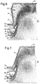
- Figure 6 shows a plot of air and fuel/air mixture flows issuing form the injector of Figure 5.
- the drawing shows a part of a combustor from an injector centre line outwards in a radial section.
- the combustor back wall is slightly dished, ie concave, radially outwards of the injector ports.
- HP compressor air flows through the passages 58,59.
- Fuel issues from the passage 34 into the airstream in the centre passage 29 and forms a plume of fuel/air mixture issuing from the frusto-conical nozzle.
- the concentric passage 58 immediately downstream of nozzle in combination with the flared lip 55, 56 has the effect of opening out the mixture plume into a wide-angle cone.
- the passage 59 defined between the seal member 54 and the radially outer surface of the flared lip member 56 feeds a flow of relatively cool HP compressor air into the recirculation zone 60 between the wide-angle mixture cone and the back wall 47, as illustrated in Figure 4.
- an effusion cooling flow through small cooling holes in the back wall in the region 61 for example as leakage flow from thermal wall protection tiles, if provided, is entrained into this recirculation of cooling air.
- the shape of the combustor back wall 47 is modified to have a conical form surrounding each fuel injector.
- the cone angle is substantially equal to the cone angle of the fuel/air mixture cone. This eliminates the cooling air recirculation zone, as can be seen by comparison of the flow diagrams of Figures 6 and 7.
- the cooling air flow issuing from passage 54 now flows radially outwards from the fuel injector centre line and parallel to the back wall 47. In this arrangement the effusion cooling flow through the combustor back wall may be dispensed with.
Landscapes
- Engineering & Computer Science (AREA)
- Chemical & Material Sciences (AREA)
- Combustion & Propulsion (AREA)
- Mechanical Engineering (AREA)
- General Engineering & Computer Science (AREA)
- Spray-Type Burners (AREA)
Abstract
Description
- This invention relates to a gas turbine engine fuel injector. In particular, the invention concerns a multi-stream fuel injector for the combustor of a gas turbine engine.
- A fuel injector of this type produces a generally conical pattern of swirling flows of air and/or an air/fuel mixture concentric with the longitudinal axis of the injector. The radially outward component of the conical flow from the injector can give rise to hot flow recirculation around the fuel injector outlet. Such flow recirculation regions are undesirable since they trap hot combustion products and can even support a flame. This, in turn, leads to local overheating of the fuel injector and surrounding combustor walls resulting in erosion damage and adverse thermal effects upon structures in the region of the fuel injector.
- The present invention is intended to overcome these drawbacks by providing an improved fuel injector design which avoids hot flow recirculation regions.
- According to the present invention a gas turbine engine fuel injector of the kind having a plurality of concentric passages comprises radially outwards of a fuel passage at least one passage for the flow therethrough of air, the downstream end of said passage having a radially inwardly directed annular lip, the cross-sectional shape of which is such that in said at least one passage air flowing over said lip remains attached to the surface of said lip so as to flow thereover in a substantially non-turbulent manner initially in a generally radially inward direction and subsequently in a generally radially outward direction.
- Preferably in one arrangement a multi-stream fuel injector is installed in a combustor, wherein the fuel injector is located in an upstream wall of the combustor and the flared lip member is adapted to produce, in use, a radially outward flow of cooling air in contact with the face of the surrounding combustor wall.
- In another arrangement the fuel injector is located in an upstream wall of the combustor and the flared lip member is adapted to produce, in use, a recirculation region of cooling air adjacent the combustor wall surrounding the injector.
- The present invention will now be described, by way of example, with reference to the accompanying drawings in which:
- Figure 1 is a schematic diagram of a ducted fan gas turbine engine having an annular combustor,
- Figure 2 is a detail close-up view of part of the combustor of the engine of Figure 1,
- Fig 3 is a partially sectioned side view of a first embodiment of a fuel injector in accordance with the present invention as used in the combustor of Fig 2,
- Figure 4 illustrates a flow pattern of the multi-stream fuel injector of Fig 3,
- Figure 5 is a side view of an alternative, second embodiment of a fuel injector in accordance with the present invention,
- Figure 6 is an illustration of the fuel/air distribution pattern of the fuel injector of Figure 5 with a first design of combustor end wall, and
- Figure 7 is a corresponding illustration of the fuel/air distribution pattern of the fuel injector of Fig 5 with a second design of combustor end wall.
- With reference to Fig 1, there is shown a three-shaft ducted fan gas turbine engine generally of generally conventional configuration. It will be understood, however, that the invention to described hereinafter may be found useful in other engine layouts. The engine of Fig 1 comprises, in axial flow series: a low pressure spool consisting of a
fan 2 driven by a low pressure turbine 4 via afirst shaft 6; anintermediate compressor 8 driven by anintermediate pressure turbine 10 through a second shaft 12; and ahigh pressure compressor 14 driven by ahigh pressure turbine 16 via athird shaft 18; anannular combustor 20 and apropulsive nozzle 21. - A portion of the
annular combustor 20 is shown in more detail in Figure 2. In this and subsequent figures like parts have like references. Thecombustor 20 is located within a combustion chamberouter casing 22 which defines the outer boundary of the airflow region around the combustion chamber itself. The combustor orchamber 20 is formed by concentric outer andinner walls walls - Air is admitted to the interior of the
combustion chamber 20 through a multiplicity of apertures formed in thewalls combustor 20 through a plurality of fuel injectors, of which one is indicated at 25, which are spaced apart around the upstream chamber wall formed by the convergence of the inner andouter walls - Internal details of a first embodiment of a
fuel injector 25 according to the invention is illustrated in Fig 3. The injector comprises amain body 26 which is carried by the distal end of anarm 27. Thearm 27 is formed with an internal fuel duct 28 through which fuel is supplied to the main body of thefuel injector 25. - The
main body 26 of the injector has acentral air passage 29 which is open at both ends and extends from itsupstream end 30, on the left of Fig 3, towards itsdownstream end 31, on the right. Thepassage 29 is concentric with alongitudinal axis 32 of thebody 26 and fuel nozzle. The nozzle is defined by a series of concentric frusto-conical rings. Anannular fuel gallery 33 is formed in the interior of theinjector body 26 and receives fuel from the duct 28. The downstream end of thegallery 33 is formed into anannular orifice 34 by concentric generally frusto-conical rings - Radially outwards of the
fuel orifice 34 are two furtherconcentric rings rings 40 is mounted on theinjector body 26 by means of an annular array ofswirler vanes 38 and has a frusto-conical downstream shape surrounding the fuel orifice. The outer of the tworings 42 is similarly mounted on theinner ring 40 by means of a further array ofswirler vanes 39 and is also shaped at its downstream end. - When high pressure air is delivered to the
upstream end 30 of thefuel injector 25 by thehigh pressure compressor 14, some of that air flows through thecentral passage 29. This air interacts with the annular, radially inwardly directed film of fuel which issues from anannular orifice 34. Further high pressure air flows around the fuel injectormain body 26 and through the two arrays ofswirler vanes orifice 34 to cause atomization of the fuel. The interaction between the various fuel and air flows results in the atomized fuel being ejected from thefuel injector 25 into thecombustor 20 in this initially convergent shape which expands in a divergent manner as indicated by thearrows 41. - The divergent flow of fuel and air is reinforced by the flow of air which is exhausted from the radially outermost array of
swirler vanes 39. Thisouter ring 42 is provided at its downstream end with a smoothly profiled radially inwardly directedannular lip 43. Theannular lip 43 extends across the flow path of the air exhausted from the radiallyoutermost swirler vanes 39 so as to direct that air initially in a generally radially inward direction. However, thelip 43 has a flared configuration formed by a generally U-shaped cross-sectional shape. The shape is such that the air which flows over the surface of thelip 43 by virtue of the coanda effect remains attached to the surface. This ensures that the air flows over the surface in a generally non-turbulent manner and is also turned by coanda effect so that the air flow which finally exhausted from between therings arrows 41. - The fuel injector of Figure 3 is designed as an integral assembly comprising the
main body 26 together with theconcentric rings outermost ring 42 is formed as a constant diameter cylindrical surface intended to fit into a parallel, smooth sided bore in the end wall of the combustor. In Figure 3 thisbore 44 is provided by an internal surface of an axially extendingflange 45 formed on amounting ring 46 attached to thecombustor end wall 47. It is found, in practise, that the smooth flow characteristics of the fuel injector can be improved by providing aflared lip 48 on the periphery of themounting ring flange 45 which protrudes a short distance into thecombustion chamber volume 20. In effect theflared lip 48 becomes a radially outward extension of theintegral injector lip 43. Atomized fuel and air are thereby appropriately placed within thecombustion chamber 20 in order to support efficient combustion. - The avoidance of turbulent flow in the air which flows over the surface of the
lip 43 ensures that regions of fuel/air mixture recirculation do not occur around thefuel injector 25. Consequently regions of overheating are thereby largely avoided. - However, two effects have been observed which can mitigate some of the benefits brought about by the invention. Any recirculatory flow which does occur on the radially outer side of the
mounting ring 46 is fed with only a small flow of leakage or bleed cooling air metered through small effusion holes in the radially flanged portion of thering 46. As a result the residence time of this air can be sufficiently long to cause incipient overheating. The second effect arises as the fuel injector is permitted to move axially relative to theend wall 47 either as a result of differential thermal expansion or as a control function. Such differential movement of the cooperatinglips end wall 47 is normally provided with a heatshield on its combustor side and a flow of cooling air is allowed to bleed into the region around the circumference of theinjector mounting ring 46. This bleed flow can be trapped by an injector flow recirculation pattern, denoted byarrows 49. Unfortunately the bleed flow has a relatively low mass flow rate, compared to flow rate of airstreams through the injector itself. As a result residence time adjacent the face of the heatshield is increased and therefore its efficiency reduced. - Figure 4 shows a flow circulation diagram for the first embodiment of the invention illustrated in Figure 3. There is shown a combustion chamber in which the
upstream wall 47 of the combustor lies in a radial plane and the injector forms a wide cone angle fuel/air mixture distribution. The combination of flaredlips combustion volume 20, but is also shown generating a recirculation of the relatively low mass flow bleed cooling air flow inregion 49 on the lee side of thelip 48. Although the flaredlips portion 48 forms part of the combustor rather than being part of the fuel injector. As a result thelip 48 remains behind in situ when the injector is withdrawn and, during use, relative axial movement between the injector and the combustor wall can disturb the flow pattern by creating a discontinuity in the lip profile. - The second embodiment of a multi-stream injector illustrated in Figure 5 provides an injector design incorporating a flared lip wholly within the demountable portions of the injector. Those parts of the second embodiment of Figure 5 which correspond to similar members in the first embodiment of Figure 3 carry like references. Thus the
main body 26 of the injector is unchanged, as are the integral frusto-conical members fuel orifice 34. - Radially outwards of the
ring 36 once again there two concentric swirled air channels the constructions of which include thesame swirler vanes concentric members concentric members inner member 52 now carries acoanda lip 55 and an outwardly flaredlip 56 and is carried by the swirl vanes 38. These shapedlips outermost ring 54 is now merely a plain cylindrical ring although it too is an integral part of theinjector 25 and carried by the radially outer swirl vanes 39. The outer surface of theouter ring 54 is slidably engaged with alip 57 formed inwall 47 surrounding and defining the fuel injector aperture.. - There is now, in use, a fast flowing cool airstream on both radially inner and radially outer sides of the
member 52 inannular channels - Installed in a combustor the outermost
concentric member 54 may be inserted into a mounting ring, as in Fig 3, or into the closelyfitting aperture 57 in the upstream end wall of the combustion chamber. Themember 54 acts as a seal around the injector to prevent uncontrolled leakage of air into the combustion volume. The downstream rim of the outermost concentric or sealmember 54 is substantially flush with the surrounding margin of the combustor end wall. Furthermore the diameter of the radially outwardly extending rim of the flaredlip 56 extends no further radially outwards than the circumference of of themember 54. Thus, the whole injector assembly of Fig 5, including the flared lip portion, can be withdrawn from the combustion chamber as a single unit. - Figure 6 shows a plot of air and fuel/air mixture flows issuing form the injector of Figure 5. The drawing shows a part of a combustor from an injector centre line outwards in a radial section. The combustor back wall is slightly dished, ie concave, radially outwards of the injector ports. With the fuel injector of Figure 5 HP compressor air flows through the
passages passage 34 into the airstream in thecentre passage 29 and forms a plume of fuel/air mixture issuing from the frusto-conical nozzle. Theconcentric passage 58 immediately downstream of nozzle in combination with the flaredlip back wall 47 of the combustor this recirculation flow is at least almost wholly cold flow entrapped from the flow throughchannel 59 on the radially outer side of the flared lip member. - According to the modification of the present invention shown in Figure 3 the
passage 59 defined between theseal member 54 and the radially outer surface of the flaredlip member 56 feeds a flow of relatively cool HP compressor air into therecirculation zone 60 between the wide-angle mixture cone and theback wall 47, as illustrated in Figure 4. In addition, an effusion cooling flow through small cooling holes in the back wall in theregion 61, for example as leakage flow from thermal wall protection tiles, if provided, is entrained into this recirculation of cooling air. - In the arrangement illustrated in Figure 7 the shape of the combustor back
wall 47 is modified to have a conical form surrounding each fuel injector. The cone angle is substantially equal to the cone angle of the fuel/air mixture cone. This eliminates the cooling air recirculation zone, as can be seen by comparison of the flow diagrams of Figures 6 and 7. The cooling air flow issuing frompassage 54 now flows radially outwards from the fuel injector centre line and parallel to theback wall 47. In this arrangement the effusion cooling flow through the combustor back wall may be dispensed with. - Although the present invention has been described with reference to a fuel injector passage which contains a flow of air, it will be appreciated that it could also be applied to a fuel injector passage which contains a flow of air and fuel if there is a danger of flow recirculation regions occurring in that fuel and air flow.
Claims (12)
Applications Claiming Priority (4)
| Application Number | Priority Date | Filing Date | Title |
|---|---|---|---|
| GB9407866A GB9407866D0 (en) | 1994-04-20 | 1994-04-20 | Multi-steam fuel injector |
| GB9407820A GB9407820D0 (en) | 1994-04-20 | 1994-04-20 | Gas turbine engine fuel injector |
| GB9407866 | 1994-04-20 | ||
| GB9407820 | 1994-04-20 |
Publications (3)
| Publication Number | Publication Date |
|---|---|
| EP0678708A2 true EP0678708A2 (en) | 1995-10-25 |
| EP0678708A3 EP0678708A3 (en) | 1996-04-24 |
| EP0678708B1 EP0678708B1 (en) | 1998-12-02 |
Family
ID=26304742
Family Applications (1)
| Application Number | Title | Priority Date | Filing Date |
|---|---|---|---|
| EP95302558A Expired - Lifetime EP0678708B1 (en) | 1994-04-20 | 1995-04-18 | Gas turbine engine fuel injector |
Country Status (3)
| Country | Link |
|---|---|
| US (1) | US5737921A (en) |
| EP (1) | EP0678708B1 (en) |
| DE (1) | DE69506308T2 (en) |
Cited By (8)
| Publication number | Priority date | Publication date | Assignee | Title |
|---|---|---|---|---|
| EP1096206A1 (en) * | 1999-11-01 | 2001-05-02 | General Electric Company | Low emissions combustor |
| NL1017045C2 (en) * | 2001-01-08 | 2002-07-09 | Elbar Bv | Gas flow layer formation device utilising Coanda effect, especially for burner devices, generates spiral gas flow inside passage exiting at surface on which this layer is formed |
| EP1193448A3 (en) * | 2000-09-29 | 2003-05-28 | General Electric Company | Multiple annular combustion chamber swirler having atomizing pilot |
| FR2944062A1 (en) * | 2009-04-06 | 2010-10-08 | Snecma | Tricoaxial structure type injector for injecting e.g. liquid hydrogen in combustion chamber of rocket engine, has aerodynamic bowl fixed at downstream end of injector body and widened toward inner side of combustion body |
| WO2011136834A2 (en) | 2009-12-30 | 2011-11-03 | Rolls-Royce Corporation | Gas turbine engine having dome panel assembly with bifurcated swirler flow |
| EP2385306A3 (en) * | 2010-05-07 | 2017-07-26 | Rolls-Royce Deutschland Ltd & Co KG | Lean pre-mix burner of a gas turbine engine with flow guidance element |
| WO2017187104A1 (en) * | 2016-04-28 | 2017-11-02 | Safran Aircraft Engines | Air intake swirler for a turbomachine injection system comprising an aerodynamic deflector at its inlet |
| EP3453973A1 (en) * | 2017-09-08 | 2019-03-13 | Rolls-Royce plc | Fuel spray nozzle |
Families Citing this family (53)
| Publication number | Priority date | Publication date | Assignee | Title |
|---|---|---|---|---|
| US6067790A (en) * | 1996-01-05 | 2000-05-30 | Choi; Kyung J. | Lean direct wall fuel injection method and devices |
| US5921470A (en) * | 1997-03-20 | 1999-07-13 | Kamath; Bola R. | Air-atomizing oil burner utilizing a low pressure fan and nozzle |
| US6164074A (en) * | 1997-12-12 | 2000-12-26 | United Technologies Corporation | Combustor bulkhead with improved cooling and air recirculation zone |
| GB9726697D0 (en) * | 1997-12-18 | 1998-02-18 | Secr Defence | Fuel injector |
| US6161387A (en) * | 1998-10-30 | 2000-12-19 | United Technologies Corporation | Multishear fuel injector |
| US6883332B2 (en) * | 1999-05-07 | 2005-04-26 | Parker-Hannifin Corporation | Fuel nozzle for turbine combustion engines having aerodynamic turning vanes |
| US6460344B1 (en) * | 1999-05-07 | 2002-10-08 | Parker-Hannifin Corporation | Fuel atomization method for turbine combustion engines having aerodynamic turning vanes |
| RU2183798C2 (en) * | 1999-09-23 | 2002-06-20 | Открытое акционерное общество Уральский завод тяжелого машиностроения | Burner device |
| US6547163B1 (en) * | 1999-10-01 | 2003-04-15 | Parker-Hannifin Corporation | Hybrid atomizing fuel nozzle |
| US6354072B1 (en) * | 1999-12-10 | 2002-03-12 | General Electric Company | Methods and apparatus for decreasing combustor emissions |
| US6272840B1 (en) * | 2000-01-13 | 2001-08-14 | Cfd Research Corporation | Piloted airblast lean direct fuel injector |
| US6688534B2 (en) * | 2001-03-07 | 2004-02-10 | Delavan Inc | Air assist fuel nozzle |
| US6484489B1 (en) | 2001-05-31 | 2002-11-26 | General Electric Company | Method and apparatus for mixing fuel to decrease combustor emissions |
| US6418726B1 (en) | 2001-05-31 | 2002-07-16 | General Electric Company | Method and apparatus for controlling combustor emissions |
| US6543235B1 (en) | 2001-08-08 | 2003-04-08 | Cfd Research Corporation | Single-circuit fuel injector for gas turbine combustors |
| ES2295423T3 (en) * | 2001-12-20 | 2008-04-16 | Alstom Technology Ltd | PROCEDURE FOR INJECTION OF A FUEL / AIR MIXTURE IN A COMBUSTION CHAMBER. |
| DE10326720A1 (en) * | 2003-06-06 | 2004-12-23 | Rolls-Royce Deutschland Ltd & Co Kg | Burner for a gas turbine combustor |
| WO2005016548A1 (en) * | 2003-08-13 | 2005-02-24 | Unilever Plc | Nozzle for a spray device |
| US7117678B2 (en) * | 2004-04-02 | 2006-10-10 | Pratt & Whitney Canada Corp. | Fuel injector head |
| US20060156733A1 (en) * | 2005-01-14 | 2006-07-20 | Pratt & Whitney Canada Corp. | Integral heater for fuel conveying member |
| US7565807B2 (en) * | 2005-01-18 | 2009-07-28 | Pratt & Whitney Canada Corp. | Heat shield for a fuel manifold and method |
| US20060162338A1 (en) * | 2005-01-21 | 2006-07-27 | Pratt & Whitney Canada Corp. | Evacuation of hot gases accumulated in an inactive gas turbine engine |
| US7533531B2 (en) * | 2005-04-01 | 2009-05-19 | Pratt & Whitney Canada Corp. | Internal fuel manifold with airblast nozzles |
| US8062027B2 (en) * | 2005-08-11 | 2011-11-22 | Elster Gmbh | Industrial burner and method for operating an industrial burner |
| US7757966B2 (en) * | 2005-12-09 | 2010-07-20 | Utah State University | High-speed jet control |
| US7617689B2 (en) * | 2006-03-02 | 2009-11-17 | Honeywell International Inc. | Combustor dome assembly including retaining ring |
| US8096130B2 (en) * | 2006-07-20 | 2012-01-17 | Pratt & Whitney Canada Corp. | Fuel conveying member for a gas turbine engine |
| US8353166B2 (en) | 2006-08-18 | 2013-01-15 | Pratt & Whitney Canada Corp. | Gas turbine combustor and fuel manifold mounting arrangement |
| US7765808B2 (en) * | 2006-08-22 | 2010-08-03 | Pratt & Whitney Canada Corp. | Optimized internal manifold heat shield attachment |
| RU2327928C2 (en) * | 2006-08-22 | 2008-06-27 | Общество с ограниченной ответственностью "Уралмаш-Металлургическое оборудование" | Burner device |
| US8033113B2 (en) * | 2006-08-31 | 2011-10-11 | Pratt & Whitney Canada Corp. | Fuel injection system for a gas turbine engine |
| US20080053096A1 (en) * | 2006-08-31 | 2008-03-06 | Pratt & Whitney Canada Corp. | Fuel injection system and method of assembly |
| US7703289B2 (en) * | 2006-09-18 | 2010-04-27 | Pratt & Whitney Canada Corp. | Internal fuel manifold having temperature reduction feature |
| US7775047B2 (en) * | 2006-09-22 | 2010-08-17 | Pratt & Whitney Canada Corp. | Heat shield with stress relieving feature |
| US7926286B2 (en) | 2006-09-26 | 2011-04-19 | Pratt & Whitney Canada Corp. | Heat shield for a fuel manifold |
| US7716933B2 (en) * | 2006-10-04 | 2010-05-18 | Pratt & Whitney Canada Corp. | Multi-channel fuel manifold |
| US8572976B2 (en) * | 2006-10-04 | 2013-11-05 | Pratt & Whitney Canada Corp. | Reduced stress internal manifold heat shield attachment |
| US8015815B2 (en) * | 2007-04-18 | 2011-09-13 | Parker-Hannifin Corporation | Fuel injector nozzles, with labyrinth grooves, for gas turbine engines |
| US7856825B2 (en) * | 2007-05-16 | 2010-12-28 | Pratt & Whitney Canada Corp. | Redundant mounting system for an internal fuel manifold |
| US8146365B2 (en) * | 2007-06-14 | 2012-04-03 | Pratt & Whitney Canada Corp. | Fuel nozzle providing shaped fuel spray |
| GB0916944D0 (en) * | 2009-09-28 | 2009-11-11 | Rolls Royce Plc | Air blast fuel injector |
| FR2956897B1 (en) * | 2010-02-26 | 2012-07-20 | Snecma | INJECTION SYSTEM FOR TURBOMACHINE COMBUSTION CHAMBER, COMPRISING AIR INJECTION MEANS ENHANCING THE AIR-FUEL MIXTURE |
| US8893500B2 (en) | 2011-05-18 | 2014-11-25 | Solar Turbines Inc. | Lean direct fuel injector |
| US8919132B2 (en) | 2011-05-18 | 2014-12-30 | Solar Turbines Inc. | Method of operating a gas turbine engine |
| US9182124B2 (en) | 2011-12-15 | 2015-11-10 | Solar Turbines Incorporated | Gas turbine and fuel injector for the same |
| GB201315008D0 (en) | 2013-08-22 | 2013-10-02 | Rolls Royce Plc | Airblast fuel injector |
| GB201321193D0 (en) * | 2013-12-02 | 2014-01-15 | Rolls Royce Plc | A combustion chamber assembly |
| GB2521127B (en) | 2013-12-10 | 2016-10-19 | Rolls Royce Plc | Fuel spray nozzle |
| DE102017217329A1 (en) | 2017-09-28 | 2019-03-28 | Rolls-Royce Deutschland Ltd & Co Kg | Nozzle with axially projecting air guide for a combustion chamber of an engine |
| DE102018106051A1 (en) | 2018-03-15 | 2019-09-19 | Rolls-Royce Deutschland Ltd & Co Kg | Combustion chamber assembly with burner seal and nozzle and a Leitströmungserzeugungseinrichtung |
| US11253823B2 (en) * | 2019-03-29 | 2022-02-22 | Delavan Inc. | Mixing nozzles |
| DE102020106842A1 (en) | 2020-03-12 | 2021-09-16 | Rolls-Royce Deutschland Ltd & Co Kg | Nozzle with jet generator channel for fuel to be injected into a combustion chamber of an engine |
| GB202405296D0 (en) * | 2024-04-15 | 2024-05-29 | Rolls Royce Plc | Nozzle body for fuel injector |
Family Cites Families (18)
| Publication number | Priority date | Publication date | Assignee | Title |
|---|---|---|---|---|
| US3638865A (en) * | 1970-08-31 | 1972-02-01 | Gen Electric | Fuel spray nozzle |
| GB1283827A (en) * | 1970-09-26 | 1972-08-02 | Rolls Royce | Improvements in or relating to combustion apparatus |
| US3961475A (en) * | 1972-09-07 | 1976-06-08 | Rolls-Royce (1971) Limited | Combustion apparatus for gas turbine engines |
| US3905192A (en) * | 1974-08-29 | 1975-09-16 | United Aircraft Corp | Combustor having staged premixing tubes |
| GB2035540B (en) * | 1978-11-23 | 1983-02-09 | Rolls Royce | Gas turbine engine fuel injector |
| US4845940A (en) * | 1981-02-27 | 1989-07-11 | Westinghouse Electric Corp. | Low NOx rich-lean combustor especially useful in gas turbines |
| JPS5892714A (en) * | 1981-11-27 | 1983-06-02 | Agency Of Ind Science & Technol | Combustor for gas turbine |
| DE3206074A1 (en) * | 1982-02-17 | 1983-08-18 | Körting Hannover AG, 3000 Hannover | BURNERS FOR DUST-MADE, GASEOUS AND / OR LIQUID FUELS |
| US4584834A (en) * | 1982-07-06 | 1986-04-29 | General Electric Company | Gas turbine engine carburetor |
| GB2175992B (en) * | 1985-06-07 | 1988-12-21 | Rolls Royce | Gas turbine engine gaseous fuel injector |
| FR2585770B1 (en) * | 1985-08-02 | 1989-07-13 | Snecma | ENLARGED BOWL INJECTION DEVICE FOR A TURBOMACHINE COMBUSTION CHAMBER |
| DE3642122C1 (en) * | 1986-12-10 | 1988-06-09 | Mtu Muenchen Gmbh | Fuel injector |
| US4943230A (en) * | 1988-10-11 | 1990-07-24 | Sundstrand Corporation | Fuel injector for achieving smokeless combustion reactions at high pressure ratios |
| US4977740A (en) * | 1989-06-07 | 1990-12-18 | United Technologies Corporation | Dual fuel injector |
| US5117637A (en) * | 1990-08-02 | 1992-06-02 | General Electric Company | Combustor dome assembly |
| US5235813A (en) * | 1990-12-24 | 1993-08-17 | United Technologies Corporation | Mechanism for controlling the rate of mixing in combusting flows |
| FR2679010B1 (en) * | 1991-07-10 | 1993-09-24 | Snecma | TURBOMACHINE COMBUSTION CHAMBER WITH REMOVABLE PREVAPORIZATION BOWLS. |
| DE4228816C2 (en) * | 1992-08-29 | 1998-08-06 | Mtu Muenchen Gmbh | Burners for gas turbine engines |
-
1995
- 1995-04-18 DE DE69506308T patent/DE69506308T2/en not_active Expired - Lifetime
- 1995-04-18 EP EP95302558A patent/EP0678708B1/en not_active Expired - Lifetime
- 1995-04-20 US US08/425,401 patent/US5737921A/en not_active Expired - Lifetime
Cited By (13)
| Publication number | Priority date | Publication date | Assignee | Title |
|---|---|---|---|---|
| EP1096206A1 (en) * | 1999-11-01 | 2001-05-02 | General Electric Company | Low emissions combustor |
| US6279323B1 (en) | 1999-11-01 | 2001-08-28 | General Electric Company | Low emissions combustor |
| EP1193448A3 (en) * | 2000-09-29 | 2003-05-28 | General Electric Company | Multiple annular combustion chamber swirler having atomizing pilot |
| NL1017045C2 (en) * | 2001-01-08 | 2002-07-09 | Elbar Bv | Gas flow layer formation device utilising Coanda effect, especially for burner devices, generates spiral gas flow inside passage exiting at surface on which this layer is formed |
| FR2944062A1 (en) * | 2009-04-06 | 2010-10-08 | Snecma | Tricoaxial structure type injector for injecting e.g. liquid hydrogen in combustion chamber of rocket engine, has aerodynamic bowl fixed at downstream end of injector body and widened toward inner side of combustion body |
| EP2519719A4 (en) * | 2009-12-30 | 2015-02-18 | Rolls Royce Corp | Gas turbine engine having dome panel assembly with bifurcated swirler flow |
| WO2011136834A2 (en) | 2009-12-30 | 2011-11-03 | Rolls-Royce Corporation | Gas turbine engine having dome panel assembly with bifurcated swirler flow |
| US9027350B2 (en) | 2009-12-30 | 2015-05-12 | Rolls-Royce Corporation | Gas turbine engine having dome panel assembly with bifurcated swirler flow |
| EP2385306A3 (en) * | 2010-05-07 | 2017-07-26 | Rolls-Royce Deutschland Ltd & Co KG | Lean pre-mix burner of a gas turbine engine with flow guidance element |
| WO2017187104A1 (en) * | 2016-04-28 | 2017-11-02 | Safran Aircraft Engines | Air intake swirler for a turbomachine injection system comprising an aerodynamic deflector at its inlet |
| US10883718B2 (en) | 2016-04-28 | 2021-01-05 | Safran Aircraft Engines | Air intake swirler for a turbomachine injection system comprising an aerodynamic deflector at its inlet |
| EP3453973A1 (en) * | 2017-09-08 | 2019-03-13 | Rolls-Royce plc | Fuel spray nozzle |
| US11181272B2 (en) | 2017-09-08 | 2021-11-23 | Rolls-Royce Plc | Spray nozzle |
Also Published As
| Publication number | Publication date |
|---|---|
| US5737921A (en) | 1998-04-14 |
| EP0678708B1 (en) | 1998-12-02 |
| DE69506308T2 (en) | 1999-08-26 |
| EP0678708A3 (en) | 1996-04-24 |
| DE69506308D1 (en) | 1999-01-14 |
Similar Documents
| Publication | Publication Date | Title |
|---|---|---|
| EP0678708B1 (en) | Gas turbine engine fuel injector | |
| US3713588A (en) | Liquid fuel spray nozzles with air atomization | |
| US3938324A (en) | Premix combustor with flow constricting baffle between combustion and dilution zones | |
| US5490389A (en) | Combustor having enhanced weak extinction characteristics for a gas turbine engine | |
| KR102334882B1 (en) | Combustion system with panel fuel injectors | |
| EP3649403B1 (en) | Auxiliary torch ignition | |
| US3958416A (en) | Combustion apparatus | |
| US4198815A (en) | Central injection fuel carburetor | |
| US4854127A (en) | Bimodal swirler injector for a gas turbine combustor | |
| US3899884A (en) | Combustor systems | |
| JP4689777B2 (en) | Two types of fuel nozzle | |
| US8726668B2 (en) | Fuel atomization dual orifice fuel nozzle | |
| US8387391B2 (en) | Aerodynamically enhanced fuel nozzle | |
| EP0751345B1 (en) | Fuel jetting nozzle assembly for use in gas turbine combustor | |
| US5323602A (en) | Fuel/air distribution and effusion cooling system for a turbine engine combustor burner | |
| US4374466A (en) | Gas turbine engine | |
| CN108731029B (en) | Jet fuel nozzle | |
| US20120151928A1 (en) | Cooling flowpath dirt deflector in fuel nozzle | |
| JPS6161015B2 (en) | ||
| US3961475A (en) | Combustion apparatus for gas turbine engines | |
| GB1563125A (en) | Low pressure fuel injection system | |
| JPH09133326A (en) | Air blast spray nozzle | |
| WO2013115671A1 (en) | Liquid fuel nozzle for gas turbine and method for injecting fuel into a combustor of a gas turbine | |
| US11885497B2 (en) | Fuel nozzle with slot for cooling | |
| US5230214A (en) | Recirculating zone inducing means for an augmentor burning section |
Legal Events
| Date | Code | Title | Description |
|---|---|---|---|
| PUAI | Public reference made under article 153(3) epc to a published international application that has entered the european phase |
Free format text: ORIGINAL CODE: 0009012 |
|
| AK | Designated contracting states |
Kind code of ref document: A2 Designated state(s): DE FR GB |
|
| PUAL | Search report despatched |
Free format text: ORIGINAL CODE: 0009013 |
|
| AK | Designated contracting states |
Kind code of ref document: A3 Designated state(s): DE FR GB |
|
| 17P | Request for examination filed |
Effective date: 19960622 |
|
| 17Q | First examination report despatched |
Effective date: 19970624 |
|
| GRAG | Despatch of communication of intention to grant |
Free format text: ORIGINAL CODE: EPIDOS AGRA |
|
| GRAG | Despatch of communication of intention to grant |
Free format text: ORIGINAL CODE: EPIDOS AGRA |
|
| GRAH | Despatch of communication of intention to grant a patent |
Free format text: ORIGINAL CODE: EPIDOS IGRA |
|
| GRAH | Despatch of communication of intention to grant a patent |
Free format text: ORIGINAL CODE: EPIDOS IGRA |
|
| GRAA | (expected) grant |
Free format text: ORIGINAL CODE: 0009210 |
|
| AK | Designated contracting states |
Kind code of ref document: B1 Designated state(s): DE FR GB |
|
| REF | Corresponds to: |
Ref document number: 69506308 Country of ref document: DE Date of ref document: 19990114 |
|
| ET | Fr: translation filed | ||
| PLBE | No opposition filed within time limit |
Free format text: ORIGINAL CODE: 0009261 |
|
| STAA | Information on the status of an ep patent application or granted ep patent |
Free format text: STATUS: NO OPPOSITION FILED WITHIN TIME LIMIT |
|
| 26N | No opposition filed | ||
| REG | Reference to a national code |
Ref country code: GB Ref legal event code: IF02 |
|
| PGFP | Annual fee paid to national office [announced via postgrant information from national office to epo] |
Ref country code: GB Payment date: 20140428 Year of fee payment: 20 |
|
| PGFP | Annual fee paid to national office [announced via postgrant information from national office to epo] |
Ref country code: DE Payment date: 20140429 Year of fee payment: 20 Ref country code: FR Payment date: 20140417 Year of fee payment: 20 |
|
| REG | Reference to a national code |
Ref country code: DE Ref legal event code: R071 Ref document number: 69506308 Country of ref document: DE |
|
| REG | Reference to a national code |
Ref country code: GB Ref legal event code: PE20 Expiry date: 20150417 |
|
| PG25 | Lapsed in a contracting state [announced via postgrant information from national office to epo] |
Ref country code: GB Free format text: LAPSE BECAUSE OF EXPIRATION OF PROTECTION Effective date: 20150417 |