EP0678721A1 - Echangeur de chaleur du type à plaques - Google Patents
Echangeur de chaleur du type à plaques Download PDFInfo
- Publication number
- EP0678721A1 EP0678721A1 EP95302544A EP95302544A EP0678721A1 EP 0678721 A1 EP0678721 A1 EP 0678721A1 EP 95302544 A EP95302544 A EP 95302544A EP 95302544 A EP95302544 A EP 95302544A EP 0678721 A1 EP0678721 A1 EP 0678721A1
- Authority
- EP
- European Patent Office
- Prior art keywords
- communicating
- tube elements
- heat exchanger
- area
- communicating area
- Prior art date
- Legal status (The legal status is an assumption and is not a legal conclusion. Google has not performed a legal analysis and makes no representation as to the accuracy of the status listed.)
- Granted
Links
Images


Classifications
-
- F—MECHANICAL ENGINEERING; LIGHTING; HEATING; WEAPONS; BLASTING
- F28—HEAT EXCHANGE IN GENERAL
- F28D—HEAT-EXCHANGE APPARATUS, NOT PROVIDED FOR IN ANOTHER SUBCLASS, IN WHICH THE HEAT-EXCHANGE MEDIA DO NOT COME INTO DIRECT CONTACT
- F28D1/00—Heat-exchange apparatus having stationary conduit assemblies for one heat-exchange medium only, the media being in contact with different sides of the conduit wall, in which the other heat-exchange medium is a large body of fluid, e.g. domestic or motor car radiators
- F28D1/02—Heat-exchange apparatus having stationary conduit assemblies for one heat-exchange medium only, the media being in contact with different sides of the conduit wall, in which the other heat-exchange medium is a large body of fluid, e.g. domestic or motor car radiators with heat-exchange conduits immersed in the body of fluid
- F28D1/03—Heat-exchange apparatus having stationary conduit assemblies for one heat-exchange medium only, the media being in contact with different sides of the conduit wall, in which the other heat-exchange medium is a large body of fluid, e.g. domestic or motor car radiators with heat-exchange conduits immersed in the body of fluid with plate-like or laminated conduits
- F28D1/0308—Heat-exchange apparatus having stationary conduit assemblies for one heat-exchange medium only, the media being in contact with different sides of the conduit wall, in which the other heat-exchange medium is a large body of fluid, e.g. domestic or motor car radiators with heat-exchange conduits immersed in the body of fluid with plate-like or laminated conduits the conduits being formed by paired plates touching each other
- F28D1/0325—Heat-exchange apparatus having stationary conduit assemblies for one heat-exchange medium only, the media being in contact with different sides of the conduit wall, in which the other heat-exchange medium is a large body of fluid, e.g. domestic or motor car radiators with heat-exchange conduits immersed in the body of fluid with plate-like or laminated conduits the conduits being formed by paired plates touching each other the plates having lateral openings therein for circulation of the heat-exchange medium from one conduit to another
- F28D1/0333—Heat-exchange apparatus having stationary conduit assemblies for one heat-exchange medium only, the media being in contact with different sides of the conduit wall, in which the other heat-exchange medium is a large body of fluid, e.g. domestic or motor car radiators with heat-exchange conduits immersed in the body of fluid with plate-like or laminated conduits the conduits being formed by paired plates touching each other the plates having lateral openings therein for circulation of the heat-exchange medium from one conduit to another the plates having integrated connecting members
- F28D1/0341—Heat-exchange apparatus having stationary conduit assemblies for one heat-exchange medium only, the media being in contact with different sides of the conduit wall, in which the other heat-exchange medium is a large body of fluid, e.g. domestic or motor car radiators with heat-exchange conduits immersed in the body of fluid with plate-like or laminated conduits the conduits being formed by paired plates touching each other the plates having lateral openings therein for circulation of the heat-exchange medium from one conduit to another the plates having integrated connecting members with U-flow or serpentine-flow inside the conduits
-
- F—MECHANICAL ENGINEERING; LIGHTING; HEATING; WEAPONS; BLASTING
- F28—HEAT EXCHANGE IN GENERAL
- F28F—DETAILS OF HEAT-EXCHANGE AND HEAT-TRANSFER APPARATUS, OF GENERAL APPLICATION
- F28F9/00—Casings; Header boxes; Auxiliary supports for elements; Auxiliary members within casings
- F28F9/02—Header boxes; End plates
- F28F9/0246—Arrangements for connecting header boxes with flow lines
-
- F—MECHANICAL ENGINEERING; LIGHTING; HEATING; WEAPONS; BLASTING
- F28—HEAT EXCHANGE IN GENERAL
- F28F—DETAILS OF HEAT-EXCHANGE AND HEAT-TRANSFER APPARATUS, OF GENERAL APPLICATION
- F28F9/00—Casings; Header boxes; Auxiliary supports for elements; Auxiliary members within casings
- F28F9/02—Header boxes; End plates
- F28F9/0246—Arrangements for connecting header boxes with flow lines
- F28F9/0251—Massive connectors, e.g. blocks; Plate-like connectors
- F28F9/0253—Massive connectors, e.g. blocks; Plate-like connectors with multiple channels, e.g. with combined inflow and outflow channels
Definitions
- the present invention relates to a laminated heat exchanger used for the cooling cycle and the like of an air conditioning system for vehicles, constituted by laminating tube elements and fins alternately over a plurality of levels and, in particular, it relates to a laminated heat exchanger that employs the so-called 4-pass system, with each tube element being provided with a pair of tanks formed on one side so that heat exchanging medium passes through the tube element on two round-trips as it travels from the intake port to the outlet port.
- the so-called 4-pass system laminated heat exchanger is constituted, as disclosed in Japanese Unexamined Patent Publication No, S63-3153, for instance, by laminating tube elements and fins alternately over a plurality of levels with each tube element being provided with a pair of tanks on one side.
- the two tanks in this pair communicate with each other via a U-shaped passage and the tank portions in adjacent tube elements are bonded so as to form two tank groups extending in the direction of the lamination.
- One of the tank groups is partitioned in the middle to divide the inside into two communicating areas and, as shown in Figure 7, an intake port 20 is provided in one of the communicating areas 22 and an outlet port 21 is provided in the other communicating area 23.
- the heat exchanging medium that flows in through the intake port 20 travels through the first and second passes which are constituted by the tube elements located toward the intake port from the partitioning portion. It then travels through the third and fourth passes which are constituted by the tube elements located toward the outlet port from the partitioning portion to flow out through the outlet port 21.
- the heat exchanging medium used is a coolant
- the coolant becomes gradually gassified during the process of heat exchanging and expands. Therefore, in the 4-pass system heat exchangers of the prior art, in order to secure enough cross section area in the passage, fewer tube elements are located toward the intake port from partitioning portion than toward the outlet port.
- the outlet port for heat exchanging medium is provided at one end in the direction of lamination of the tube elements, the temperature of the tube elements in the vicinity of the partitioning portion (the tube elements separated from the outlet port 21 that constitute area B in Figure 7) among the tube elements constituting the third and fourth passes, increases. As a result, an even temperature distribution over the entire heat exchanger cannot be achieved. This is because when identical tube elements are used for lamination, heat exchanging medium mainly flows through the tube elements nearest the outlet port and it is not easily flow through the tube elements around the partitioning portion .
- an object to the present invention is to provide a laminated heat exchanger which minimizes the inconsistency in temperature distribution to achieve a further improvement in heat exchanger performance.
- the heat exchanger according to the present invention is constituted by laminating tube elements and fins alternately over a plurality of levels with each tube element being provided with a pair of tanks on one side and the two tanks in this pair of tanks communicating with each other via a U-shaped passage and by bonding the tank portions in adjacent tube elements to form two tank groups extending in the direction of the lamination.
- One of the tank groups is partitioned in the middle to divide the inside into a first communicating area and a second communicating area.
- the other tank group has no partitioning portion and communicates straight through.
- the heat exchanging medium flowing in through the intake port enters the first communicating area formed in one tank group and then it travels through the U-shaped passages of the tube elements constituting the first communicating area to be induced into the other tank group. After moving through the other tank group it travels through the U-shaped passages of the tube elements constituting the second communicating area to reach the second communicating area and then it flows out through the outlet port.
- the heat exchanging medium is distributed almost evenly throughout all the tube elements constituting the second communicating area, reducing inconsistency in temperature distribution.
- laminated heat exchanger 1 is, for instance, a 4-pass system evaporator that is constituted by laminating fins 2 alternately with tube elements 3 over a plurality of levels and is provided with an intake port and an outlet port for heat exchanging medium at one end in the direction of the lamination.
- a typical tube element 3 is formed by bonding two formed plates 4, 4 at their peripheral edges and is provided with two tanks 5, 5 on one side and a U-shaped passage 6 which conducts the heat exchanging medium from the tanks 5 to the other end.
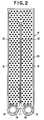
- a formed plate 4 is formed by pressing an aluminum plate and, as shown in Figure 2, it has two bowl-shaped distended portions for tank formation 8, 8 at one end and contiguous with them, a distended portion for passage formation 9 is formed.
- a projection 10 is formed in the distended portion for passage formation 9, which extends from between the distended portions for tank formation 8, 8 to the vicinity of the other end of the formed plate 4.
- an indented portion 11 for accommodating a communicating pipe, which is to be explained later, is provided between the two distended portions for tank formation 8, 8.
- a projected tab 12 shown in Figures 1A, 1B for preventing the fins 2 from coming out during assembly prior to brazing is provided.
- a plurality of beads 13 are formed at the time of pressing in order to improve the efficiency with which heat exchanging is performed.
- each bead 13 becomes bonded with the bead formed at the position facing opposite.
- Such beads 13, may be formed in any shape as long as they are rounded, i.e., they can be oval, polygonal or the like. However, if too many beads are provided, it will increase the passage resistance in the U-shaped passage 6. Therefore, they should be formed at a suitable density.
- the beads 13 are formed, as shown in Figure 2, for instance, as a plurality of bead rows which run at a right angle to the direction of the length of the tube elements 3 with the number of beads differing in adjacent bead rows. In other words, if there are three beads 13 provided at specific intervals in row n, there will be 4 beads 13 provided at the same intervals in row n+1, with 3 beads provided in row n+2 and so forth.
- each bead 13 in adjacent bead rows is positioned in such a manner that it will not lie in the wake of the preceding bead in the direction of the length of the tube elements 3 (the vertical direction in the figure).
- they are positioned in such a manner that the bead 13 that is the closest to a given bead 13 in the adjacent row, is positioned at an angle of 30x relative to the direction of the length of the tube element 3.
- a tube element 3a located at a specific position toward one side from the center, is not provided with the mounting indented portion 11 described earlier and one of its tanks 5a is extended to be close to and in contact with its other tank 5.
- the tube elements 3b at the two ends are each formed by bonding a flat plate 15 to the formed plate 4 shown in Figure 2.
- Adjacent tube elements 3 are butted at the distended portions for tank formation 8 of their respective formed plates 4 and two tank groups 16 and 17 i. e., first and second tank groups which extend in the direction of the lamination (the direction that runs at a right angle to the direction of air flow) are formed.
- first and second tank groups which extend in the direction of the lamination (the direction that runs at a right angle to the direction of air flow) are formed.
- all tanks are in communication via the communicating holes 19 formed at the distended portions for tank formation 8 except for at the partitioning portion 18 that is located approximately at the center in the direction of lamination.
- the other tank group 17 there is no partitioning portion and all the tanks are in communication via the communicating holes 19.
- a total of 21 tube elements are laminated.
- the tube element 3a with the extended tank 5a is located at the 17th position counting from the end where an intake port 20 and an outlet port 21, which are to be explained below, are formed, and the partitioning portion 18 is provided in the area where the 10th and 11th tube elements 3 counting from the end where the intake port 20 and the outlet port 21 are formed, are bonded.
- the partitioning portion 18 may constituted either by not forming a communicating hole in one of or both of the formed plates to be bonded or by using formed plates identical to the other formed plates but with the communicating hole blocked off by a blind plate when bonding them.
- the first tank group 16, with the partitioning portion 18, is divided into a first communicating area 22 which includes the extended tank 5a and a second communicating area 23, located between the outlet port t 21 and the first communicating area 22, communicating directly with the outlet port 21, while the second tank group 17, with no partition, constitutes a third communicating area 24 with 21 tanks 5 in communication.
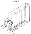
- the intake port 20 and the outlet port 21, which are provided at the end furthest from the extended tank 5b are constituted by bonding a plate for intake / outlet passage formation 25 to the flat plate 15 from the outside, forming an intake passage 28 and an outlet passage 29 extending from approximately the middle of the tube elements 3 in the direction of the length toward the tanks and providing a connecting portion 27 for connecting an expansion valve 30 (shown in Figure 3) at the plate for intake / outlet passage formation 25.
- the intake passage 28 and the extended tank 5a are connected by a communicating pipe 31 which is fitted in the indented portion 11 of the tube element 3 located between them in such a manner that they can communicate, while the second communicating area 23 and the outlet passage 29 beside it communicate with each other via the through-hole formed in the flat plate 15.
- the heat exchanging medium flowing in through the intake port 20 travels through the communicating pipe 31 to enter the tube element 3a with the extended tank 5a. Then it is distributed throughout the entirety of the first communicating area 22. It then rises through the U-shaped passages 6 of the tube elements that belong to this first communicating area 22 along the projections 10 (first pass). Next, it makes a U-turn above the projection 10 to go down (second pass) and reaches the tank group on the opposite side (third communicating area). After this, the heat exchanging medium moves horizontally to the remaining tube elements that constitute the third communicating area and goes up through the U-shaped passages 6 of the tube elements, along their projections 10 (third pass).
- the heat exchanging medium which travels through the third and fourth passes to reach the second communicating area 23 would tend to flow through the tube elements close to the outlet port 21.
- the heat exchanging medium is distributed almost consistently throughout all the tube elements.
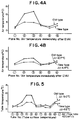
- Figures 4A, 4B, 5, 6 show a comparison between a new type of heat exchanger structured as described above, and an old type of heat exchanger which has its partitioning portion 18 provided in the area where the twelfth and thirteenth tube elements 3 counting from the end where the intake port 20 and the outlet port 21 are formed.
- the numbers above PLACE - No. indicate the locations where the temperature of the air immediately after it passes through the heat exchanger was measured and they correspond to the numbers 1 ⁇ 6 in the upper portion and 1 ⁇ 6 in the lower portion shown in Figure 1A.
- the numbers above TUBE - No. indicate the tube elements whose surface temperature was measured and they correspond with the numbers 1 ⁇ (1, 2, 3, ...) shown in Figure 1B.
- ⁇ t indicates the deviation in temperature distribution, i.e., the difference between the maximum temperature and the minimum temperature for each type.
- Figures 4A, 4B show the differences between the maximum and minimum temperatures measured at a total of 12 locations in the upper and lower areas.
- the position of the partitioning portion may change depending upon the number of laminated layers in the heat exchanger, and it should be determined by, for instance, measuring actual temperature distribution. However, it is desirable to set this position so that the ratio of the number of the tube elements constituting the first communicating area and that of the tube elements constituting the second communicating area falls within a range of 1:1 through 3:1. We set the ratio at the limit 3 : 1, since if the partitioning portion 18 is placed any closer to the outlet port 21, the second communicating area is reduced, resulting in an increase in the passage resistance and lowered heat exchanging performance.
- the embodiment takes a form in which tanks are formed as one with the tube elements. However, they can be constituted with separate members.
- the heat exchanging medium is distributed almost consistently throughout individual tube elements, reducing inconsistency in temperature distribution overall and achieving an improvement in heat exchanging performance.
Landscapes
- Engineering & Computer Science (AREA)
- Physics & Mathematics (AREA)
- Thermal Sciences (AREA)
- Mechanical Engineering (AREA)
- General Engineering & Computer Science (AREA)
- Heat-Exchange Devices With Radiators And Conduit Assemblies (AREA)
Applications Claiming Priority (2)
| Application Number | Priority Date | Filing Date | Title |
|---|---|---|---|
| JP6106089A JP3044436B2 (ja) | 1994-04-21 | 1994-04-21 | 積層型熱交換器 |
| JP106089/94 | 1994-04-21 |
Publications (2)
| Publication Number | Publication Date |
|---|---|
| EP0678721A1 true EP0678721A1 (fr) | 1995-10-25 |
| EP0678721B1 EP0678721B1 (fr) | 1998-09-09 |
Family
ID=14424829
Family Applications (1)
| Application Number | Title | Priority Date | Filing Date |
|---|---|---|---|
| EP95302544A Expired - Lifetime EP0678721B1 (fr) | 1994-04-21 | 1995-04-18 | Echangeur de chaleur du type à plaques |
Country Status (6)
| Country | Link |
|---|---|
| US (1) | US5662164A (fr) |
| EP (1) | EP0678721B1 (fr) |
| JP (1) | JP3044436B2 (fr) |
| KR (1) | KR0146488B1 (fr) |
| CN (1) | CN1119267A (fr) |
| DE (1) | DE69504564T2 (fr) |
Cited By (2)
| Publication number | Priority date | Publication date | Assignee | Title |
|---|---|---|---|---|
| EP0727625A3 (fr) * | 1995-02-16 | 1998-01-21 | Zexel Corporation | Echangeur de chaleur laminé |
| EP0841201B2 (fr) † | 1996-11-08 | 2010-09-22 | Behr GmbH & Co. KG | Installation de chauffage ou de climatisation pour véhicule à moteur. |
Families Citing this family (12)
| Publication number | Priority date | Publication date | Assignee | Title |
|---|---|---|---|---|
| JPH11287587A (ja) * | 1998-04-03 | 1999-10-19 | Denso Corp | 冷媒蒸発器 |
| KR100716029B1 (ko) * | 2000-11-20 | 2007-05-14 | 한라공조주식회사 | 적층형 열교환기 |
| KR100723810B1 (ko) * | 2001-04-10 | 2007-05-31 | 한라공조주식회사 | 열교환기 |
| US7040385B2 (en) * | 2001-10-17 | 2006-05-09 | Showa Denko K.K. | Evaporator and vehicle provided with refrigeration cycle having the same |
| KR100608574B1 (ko) * | 2005-09-07 | 2006-08-03 | 주식회사 두원공조 | 적층형 증발기 |
| JP4766110B2 (ja) * | 2008-01-10 | 2011-09-07 | 株式会社デンソー | 半導体冷却構造 |
| EP3767219A1 (fr) | 2011-10-19 | 2021-01-20 | Carrier Corporation | Échangeur de chaleur à ailettes en tube aplati et procédé de fabrication |
| WO2014116351A1 (fr) | 2013-01-28 | 2014-07-31 | Carrier Corporation | Unité d'échange thermique à plusieurs faisceaux de tubes dotée d'un ensemble de collecteur |
| ES2877092T3 (es) * | 2013-11-25 | 2021-11-16 | Carrier Corp | Intercambiador de calor de microcanal de doble trabajo |
| US10295282B2 (en) | 2014-07-21 | 2019-05-21 | Dana Canada Corporation | Heat exchanger with flow obstructions to reduce fluid dead zones |
| DE102015210231A1 (de) * | 2015-06-03 | 2016-12-08 | Bayerische Motoren Werke Aktiengesellschaft | Wärmetauscher für ein Kühlsystem, Kühlsystem sowie Baugruppe |
| EP3598046B1 (fr) * | 2018-07-20 | 2023-05-17 | Valeo Vyminiky Tepla, s.r.o. | Plaque d'échangeur de chaleur et échangeur de chaleur comprenant une telle plaque de transfert de chaleur |
Citations (1)
| Publication number | Priority date | Publication date | Assignee | Title |
|---|---|---|---|---|
| US5024269A (en) * | 1989-08-24 | 1991-06-18 | Zexel Corporation | Laminated heat exchanger |
Family Cites Families (8)
| Publication number | Priority date | Publication date | Assignee | Title |
|---|---|---|---|---|
| US4217953A (en) * | 1976-03-09 | 1980-08-19 | Nihon Radiator Co. Ltd. (Nihon Rajiecta Kabushiki Kaisha) | Parallel flow type evaporator |
| US4274482A (en) * | 1978-08-21 | 1981-06-23 | Nihon Radiator Co., Ltd. | Laminated evaporator |
| US4621685A (en) * | 1983-09-12 | 1986-11-11 | Diesel Kiki Co., Ltd. | Heat exchanger comprising condensed moisture drainage means |
| JPS6155596A (ja) * | 1984-08-24 | 1986-03-20 | Showa Alum Corp | 熱交換器 |
| JPH069738Y2 (ja) * | 1987-01-23 | 1994-03-16 | 株式会社ゼクセル | 管材のろう付け構造 |
| DE68926202T3 (de) * | 1988-09-14 | 2002-05-16 | Showa Denko K.K., Tokio/Tokyo | Kondensator |
| US5431217A (en) * | 1993-11-09 | 1995-07-11 | General Motors Corporation | Heat exchanger evaporator |
| JPH07270089A (ja) * | 1994-03-31 | 1995-10-20 | Zexel Corp | 熱交換器 |
-
1994
- 1994-04-21 JP JP6106089A patent/JP3044436B2/ja not_active Expired - Fee Related
-
1995
- 1995-04-18 EP EP95302544A patent/EP0678721B1/fr not_active Expired - Lifetime
- 1995-04-18 DE DE69504564T patent/DE69504564T2/de not_active Expired - Fee Related
- 1995-04-19 US US08/425,064 patent/US5662164A/en not_active Expired - Lifetime
- 1995-04-21 KR KR1019950009413A patent/KR0146488B1/ko not_active Expired - Fee Related
- 1995-04-21 CN CN95105771A patent/CN1119267A/zh active Pending
Patent Citations (1)
| Publication number | Priority date | Publication date | Assignee | Title |
|---|---|---|---|---|
| US5024269A (en) * | 1989-08-24 | 1991-06-18 | Zexel Corporation | Laminated heat exchanger |
Cited By (4)
| Publication number | Priority date | Publication date | Assignee | Title |
|---|---|---|---|---|
| EP0727625A3 (fr) * | 1995-02-16 | 1998-01-21 | Zexel Corporation | Echangeur de chaleur laminé |
| US6220342B1 (en) | 1995-02-16 | 2001-04-24 | Zexel Corporation | Laminated heat exchanger |
| US6227290B1 (en) * | 1995-02-16 | 2001-05-08 | Zexel Corporation | Laminated heat exchanger |
| EP0841201B2 (fr) † | 1996-11-08 | 2010-09-22 | Behr GmbH & Co. KG | Installation de chauffage ou de climatisation pour véhicule à moteur. |
Also Published As
| Publication number | Publication date |
|---|---|
| JPH07294175A (ja) | 1995-11-10 |
| KR0146488B1 (ko) | 1998-08-17 |
| DE69504564T2 (de) | 1999-06-02 |
| CN1119267A (zh) | 1996-03-27 |
| US5662164A (en) | 1997-09-02 |
| EP0678721B1 (fr) | 1998-09-09 |
| JP3044436B2 (ja) | 2000-05-22 |
| DE69504564D1 (de) | 1998-10-15 |
| KR950029748A (ko) | 1995-11-24 |
Similar Documents
| Publication | Publication Date | Title |
|---|---|---|
| US5000257A (en) | Heat exchanger having a radiator and a condenser | |
| US4274482A (en) | Laminated evaporator | |
| EP0021651B1 (fr) | Aillettes en forme de jalousie pour échangeurs de chaleur | |
| US4712612A (en) | Horizontal stack type evaporator | |
| US6220342B1 (en) | Laminated heat exchanger | |
| CA1313183C (fr) | Echangeur de chaleur a plaques | |
| EP0678721B1 (fr) | Echangeur de chaleur du type à plaques | |
| US4958681A (en) | Heat exchanger with bypass channel louvered fins | |
| US5617914A (en) | Laminated heat exchanger | |
| WO1993013376A1 (fr) | Structure d'echangeur thermique | |
| US6173764B1 (en) | Laminated heat exchanger | |
| US5881805A (en) | Laminated heat exchanger | |
| US6032729A (en) | Laminated heat exchanger | |
| US5645126A (en) | Laminated heat exchanger | |
| EP0854342B1 (fr) | L'utilisation d'un echangeur de chaleur | |
| EP0650024B1 (fr) | Elément tubulaire pour un échangeur de chaleur à structure stratifiée | |
| US5718284A (en) | Laminated heat exchanger | |
| US5893412A (en) | Laminated heat exchanger | |
| JPH0914885A (ja) | 熱交換器 | |
| JP2512471Y2 (ja) | 車両用熱交換器 | |
| KR100528997B1 (ko) | 적층형열교환기 | |
| JPS63131993A (ja) | 熱交換器 | |
| EP1310757B1 (fr) | Echangeur de chaleur du type empilé à passage multiple | |
| JPH07305985A (ja) | 多管式熱交換器 | |
| KR20000002366A (ko) | 열교환기 |
Legal Events
| Date | Code | Title | Description |
|---|---|---|---|
| PUAI | Public reference made under article 153(3) epc to a published international application that has entered the european phase |
Free format text: ORIGINAL CODE: 0009012 |
|
| AK | Designated contracting states |
Kind code of ref document: A1 Designated state(s): DE FR GB |
|
| 17P | Request for examination filed |
Effective date: 19960418 |
|
| 17Q | First examination report despatched |
Effective date: 19970421 |
|
| GRAG | Despatch of communication of intention to grant |
Free format text: ORIGINAL CODE: EPIDOS AGRA |
|
| GRAG | Despatch of communication of intention to grant |
Free format text: ORIGINAL CODE: EPIDOS AGRA |
|
| GRAH | Despatch of communication of intention to grant a patent |
Free format text: ORIGINAL CODE: EPIDOS IGRA |
|
| GRAH | Despatch of communication of intention to grant a patent |
Free format text: ORIGINAL CODE: EPIDOS IGRA |
|
| GRAA | (expected) grant |
Free format text: ORIGINAL CODE: 0009210 |
|
| AK | Designated contracting states |
Kind code of ref document: B1 Designated state(s): DE FR GB |
|
| REF | Corresponds to: |
Ref document number: 69504564 Country of ref document: DE Date of ref document: 19981015 |
|
| ET | Fr: translation filed | ||
| PLBE | No opposition filed within time limit |
Free format text: ORIGINAL CODE: 0009261 |
|
| STAA | Information on the status of an ep patent application or granted ep patent |
Free format text: STATUS: NO OPPOSITION FILED WITHIN TIME LIMIT |
|
| 26N | No opposition filed | ||
| PGFP | Annual fee paid to national office [announced via postgrant information from national office to epo] |
Ref country code: FR Payment date: 20010409 Year of fee payment: 7 Ref country code: DE Payment date: 20010409 Year of fee payment: 7 |
|
| REG | Reference to a national code |
Ref country code: GB Ref legal event code: 732E |
|
| PGFP | Annual fee paid to national office [announced via postgrant information from national office to epo] |
Ref country code: GB Payment date: 20010418 Year of fee payment: 7 |
|
| REG | Reference to a national code |
Ref country code: FR Ref legal event code: TP Ref country code: FR Ref legal event code: CD |
|
| REG | Reference to a national code |
Ref country code: GB Ref legal event code: IF02 |
|
| PG25 | Lapsed in a contracting state [announced via postgrant information from national office to epo] |
Ref country code: GB Free format text: LAPSE BECAUSE OF NON-PAYMENT OF DUE FEES Effective date: 20020418 |
|
| PG25 | Lapsed in a contracting state [announced via postgrant information from national office to epo] |
Ref country code: DE Free format text: LAPSE BECAUSE OF NON-PAYMENT OF DUE FEES Effective date: 20021101 |
|
| GBPC | Gb: european patent ceased through non-payment of renewal fee |
Effective date: 20020418 |
|
| PG25 | Lapsed in a contracting state [announced via postgrant information from national office to epo] |
Ref country code: FR Free format text: LAPSE BECAUSE OF NON-PAYMENT OF DUE FEES Effective date: 20021231 |
|
| REG | Reference to a national code |
Ref country code: FR Ref legal event code: ST |