EP0678731A1 - Système de navigation pour véhicule - Google Patents
Système de navigation pour véhicule Download PDFInfo
- Publication number
- EP0678731A1 EP0678731A1 EP95105194A EP95105194A EP0678731A1 EP 0678731 A1 EP0678731 A1 EP 0678731A1 EP 95105194 A EP95105194 A EP 95105194A EP 95105194 A EP95105194 A EP 95105194A EP 0678731 A1 EP0678731 A1 EP 0678731A1
- Authority
- EP
- European Patent Office
- Prior art keywords
- road map
- vehicle
- birds
- eye view
- visual
- Prior art date
- Legal status (The legal status is an assumption and is not a legal conclusion. Google has not performed a legal analysis and makes no representation as to the accuracy of the status listed.)
- Granted
Links
Images


Classifications
-
- G—PHYSICS
- G06—COMPUTING OR CALCULATING; COUNTING
- G06T—IMAGE DATA PROCESSING OR GENERATION, IN GENERAL
- G06T15/00—Three-dimensional [3D] image rendering
- G06T15/10—Geometric effects
- G06T15/20—Perspective computation
-
- G—PHYSICS
- G01—MEASURING; TESTING
- G01C—MEASURING DISTANCES, LEVELS OR BEARINGS; SURVEYING; NAVIGATION; GYROSCOPIC INSTRUMENTS; PHOTOGRAMMETRY OR VIDEOGRAMMETRY
- G01C21/00—Navigation; Navigational instruments not provided for in groups G01C1/00 - G01C19/00
- G01C21/26—Navigation; Navigational instruments not provided for in groups G01C1/00 - G01C19/00 specially adapted for navigation in a road network
- G01C21/34—Route searching; Route guidance
- G01C21/36—Input/output arrangements for on-board computers
- G01C21/3626—Details of the output of route guidance instructions
- G01C21/3635—Guidance using 3D or perspective road maps
-
- G—PHYSICS
- G01—MEASURING; TESTING
- G01C—MEASURING DISTANCES, LEVELS OR BEARINGS; SURVEYING; NAVIGATION; GYROSCOPIC INSTRUMENTS; PHOTOGRAMMETRY OR VIDEOGRAMMETRY
- G01C21/00—Navigation; Navigational instruments not provided for in groups G01C1/00 - G01C19/00
- G01C21/26—Navigation; Navigational instruments not provided for in groups G01C1/00 - G01C19/00 specially adapted for navigation in a road network
- G01C21/34—Route searching; Route guidance
- G01C21/36—Input/output arrangements for on-board computers
- G01C21/3667—Display of a road map
- G01C21/367—Details, e.g. road map scale, orientation, zooming, illumination, level of detail, scrolling of road map or positioning of current position marker
Definitions
- the present invention relates to a vehicle navigation system or a vehicle route guiding system for displaying a road map in the vicinity of the current vehicle position to guide the vehicle along the displayed road map, and more specifically to a vehicle navigation system which can change the contraction scale ratio of the displayed road map according to various vehicle travel conditions.
- a vehicle navigation system for calculating a recommendable vehicle travel route from a start position to a destination and for displaying the road map in the vicinity of the current vehicle position to guide the vehicle along the recommendable route is well known.
- the displayed road map is exchanged with a new one whenever the vehicle travels by a predetermined distance, so that the current vehicle position can be always displayed on the road map.
- the road maps are exchanged frequently, with the result that the driver cannot see well or confirm securely various road information displayed on the display unit together with the road map.
- Japanese Published Unexamined (Kokai) Patent Application No. 2-130412 discloses such a vehicle navigation system that the contraction scale ratio of the road maps is kept always constant and only the road information is changed according to the vehicle travel speed, for instance in such a way that only the important road information of express highways or major national roads is displayed when the vehicle travels at high speed.
- Japanese Published Unexamined Patent Application No. 2-61690 discloses a superimposed method such that two road maps of large and small contraction scale ratios are displayed simultaneously on the same display unit. In this method, the vicinity of the current vehicle position is displayed in a relatively large contraction scale ratio and positions far away from the current vehicle position is displayed in a relatively small contraction scale ratio.
- the road map in the form of an birds-eye view.
- the road map is displayed as if seen from the sky obliquely downward, which is well known in the field of the flight simulator.
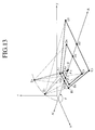
- FIG. 2 This birds-eye view will be explained in further detail with reference to Fig. 2, in which the topography (ground) lies in an XY plane, and a visual point E (x, y, z) is determined on a Z axis perpendicular to the XY plane.
- a rectangle abcd is a range actually displayed on the display unit, and a road map range seen from the visual point E through the rectangle abcd is a broad ground range ABCD.
- the birds-eye view it is possible to see road map data lying in the rectangle ABCD much broader than the displayed rectangle abcd.
- this method since an image can be displayed as if a broad trapezoidal range ABCD were seen from a visual point E, this method is referred to as an birds-eye (air or bird's eye) view display method.
- this birds-eye view display method there exists such an advantage that a center f of the rectangle abcd representative of the displayed range corresponds to a position F in the trapezoid ABCD and further this point F is located near the side AB rather than the side CD of the trapezoid ABCD. Accordingly, the range from the side AB to the point F can be displayed in the lower half of the display unit. Further, since the side AB is shorter than the side CD, the side AB can be displayed as an enlarged view.
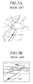
- Fig. 3B shows an example of the birds-eye view, in which a recommendable vehicle travel route from a start position to a destination is shown together with the vicinity thereof the current vehicle position CVP in the birds-eye view method.
- the visual point is set in the sky opposite to the destination (behind the current vehicle position), and the ground (topography) is seen from above in the vehicle travel direction.
- the current vehicle travel position CVP is also shown in the birds-eye view road map as an arrow.
- the map contraction scale ratio increases continuously with increasing distance from the current vehicle position; in other words, the vicinity of the current vehicle position can be enlarged and further the recommendable route can be displayed far to the destination.
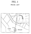
- Fig. 3A shows an example of the usual display, in which the current vehicle position CVP is indicated on roughly the same position on the map as that shown in Fig. 3B.
- the current vehicle position CVP and the vicinity thereof can be displayed in an enlarged scale, the recommendable route is displayed only at a short distance.
- the ground range to be displayed on the display unit is largely dependent upon the location of the visual point and the visual direction (the vertical overlook angle to the ground and the horizontal visual line direction.
- the visual point and the visual direction are not correct, the satisfactory display range required for the driver cannot be displayed. Accordingly, if only the visual point is set so that the current vehicle position can be displayed on the display unit, when the visual direction is not determined correctly, it is impossible to sufficiently display the ground from the current vehicle position to the destination.
- the recommendable route can be displayed to as far a distance away from the current vehicle position as possible.
- the object of the present invention to provide a vehicle navigation system which can control the visual point and the contraction scale ratio of the displayed road maps of birds-eye view according to the vehicle travel speed.
- the other object of the present invention is to provide a vehicle navigation system which can display the road map of birds-eye view in such a way the visual point and/or the visual direction for birds-eye view can be adjusted according to the distance between the current vehicle position and the nearest intersection to be guided, so that the driver can well see the road map and thereby can be well guided in accordance with the road map.
- the present invention provides a vehicle navigation system, comprising: vehicle position setting means (9) for setting a start point and a destination of a vehicle; vehicle speed sensing means (2) for detecting vehicle travel speed; vehicle travel azimuth detecting means (1) for detecting vehicle travel direction; road map data storing means (3) for storing road map data related to various roads; vehicle position detecting means (4A) for detecting a current vehicle position (CVP) on the basis of the detected vehicle speed and travel direction after the start point and in accordance with road map data; recommendable route calculating means (4B) for calculating a recommendable route from the start point to the destination on the basis of the road map data; birds-eye view forming means (4E) for forming various birds-eye view road maps of different visual points (E) and different contraction scale ratios according to vehicle travel conditions; and display means (8) for displaying the formed birds-eye view road map.
- vehicle position setting means 9 for setting a start point and a destination of a vehicle
- vehicle speed sensing means (2) for detecting vehicle travel speed
- the first aspect of the present invention provides a vehicle navigation system, comprising: vehicle position setting means (9) for setting a start point and a destination of a vehicle; vehicle speed sensing means (2) for detecting vehicle travel speed; vehicle travel azimuth detecting means (1) for detecting vehicle travel direction; road map data storing means (3) for storing road map data related to various roads; vehicle position detecting means (4A) for detecting a current vehicle position (CVP) on the basis of the detected vehicle speed and travel direction after the start point and in accordance with road map data; recommendable route calculating means (4B) for calculating a recommendable route from the start point to the destination on the basis of the road map data; birds-eye view forming means (4E) for forming an birds-eye view road map taken from a visual point (E) located in the sky behind the current vehicle position; the visual point (E) being determined on the basis of a visual line end position (F), a visual line length (
- the birds-eye view forming means sets the visual line end position (F) near the current vehicle position so that the detected current vehicle position (CVP) can be displayed substantially at the same position on the display means, irrespective of the vehicle travel speed.
- the birds-eye view forming means sets the visual point (E) to a higher point (E2) far behind away from the current vehicle position (CVP) when vehicle travel speed is high, but to a lower point (E1) near behind away from the current vehicle position when the vehicle travel speed is low, while keeping the vertical overlook angle ( ⁇ ) at a constant value, irrespective of the vehicle travel speed.
- the birds-eye view forming means sets the visual point (E) to a lower point (E3) far behind away from the current vehicle position (CVP) when vehicle travel speed is high, but to a higher point (E4) near behind away form the current vehicle position when the vehicle travel speed is low, while keeping the visual line length (
- the visual point (E) of the taken birds-eye view are changed continuously or stepwise according to vehicle travel speed.
- the birds-eye view forming means sets the horizontal visual line direction ( ⁇ ) to a vehicle travel direction detected by said azimuth detecting means.
- the birds-eye view forming means sets the horizontal visual line direction ( ⁇ ) to a direction in which the calculated recommendable route can be display over the longest distance on the display means.
- the birds-eye view forming means sets the horizontal visual line direction ( ⁇ ) to a direction of the destination.
- the second aspect of the present invention provides a vehicle navigation system, comprising: vehicle position setting means (9) for setting a start point and a destination of a vehicle; vehicle speed sensing means (2) for detecting vehicle travel speed; vehicle travel azimuth detecting means (1) for detecting vehicle travel direction; road map data storing means (3) for storing road map data related to various roads; vehicle position detecting means (4A) for detecting a current vehicle position (CVP) on the basis of the detected vehicle speed and travel direction after the start point and in accordance with road map data; recommendable route calculating means (4B) for calculating a recommendable route from the start point to the destination on the basis of the road map data; specific point extracting means (4C) for extracting specific traffic points for the vehicle to be guided from the calculated recommendable route; distance comparing means (4D) for comparing a distance (d) between the current vehicle position and one of the extracted specific traffic points with a predetermined value (D); birds-eye view forming means (4E) for forming an birds-eye view road map taken from a visual point
- one of the extracted specific traffic points is a nearest guide intersection crossing the recommendable route.
- the birds-eye view forming means sets the visual line end position (F) to the nearest guide intersection, to display the nearest guide intersection substantially vertically on the display means, when the compared distance (d) to the nearest guide intersection is shorter than the predetermined value (D); but to a point a predetermined distance ahead from the current vehicle position along the recommendable route, to display the recommendable route substantially vertically on the display means, when the compared distance (d) to the nearest guide intersection is longer than the predetermined value (D).
- the birds-eye view forming means sets the visual line end position (F) to a point in the vehicle travel direction, to display the vehicle travel direction substantially vertically on the display means, when the compared distance (d) to the nearest guide intersection is shorter than the predetermined value (D); but to a point a predetermined distance ahead from the current vehicle position along the recommendable route, to display the recommendable route substantially vertically on the display means, when the compared distance (d) to the nearest guide intersection is longer than the predetermined value (D).
- the birds-eye view forming means sets the vertical overlook angle ( ⁇ ) at which the recommendable route can be displayed over the longest distance, by calculating several displayed recommendable routes within the vertical overlook limit angle ( ⁇ ) determined according to the detected distance between the current vehicle position to the nearest guide intersection.
- the birds-eye view forming means sets the visual point (E) to a lower point (E1) near behind away from the current vehicle position (CVP) when the compared distance (d) to the nearest guide intersection is shorter than the predetermined value (D), but to a higher point (E2) far behind away form the current vehicle position when the compared distance to the nearest guide intersection is longer than the predetermined value, while keeping the vertical overlook angle ( ⁇ ) at a constant value irrespective of the distance between the two; said birds-eye view forming means further setting the visual line end position (F) to a line between the current vehicle position and the nearest guide intersection to display the nearest guide intersection substantially vertically on the display means, irrespective of the distance between the two.
- the birds-eye view forming means sets the visual point (E) to a higher point (E4) near behind away from the current vehicle position (CVP) when the compared distance (d) to the nearest guide intersection is shorter than the predetermined value (D), but to a lower point (E3) far behind away form the current vehicle position when the compared distance to the nearest guide intersection is longer than the predetermined value, while keeping a distance (EF) between the visual point (E) and the current vehicle position (CVP) at a constant value irrespective of the distance between the two; said birds-eye view forming means further setting the visual line end position (F) to a line between the current vehicle position and the nearest guide intersection or an extension line thereof to display the nearest guide intersection substantially vertically on the display means, irrespective of the distance between the two.
- the first aspect of the present invention provides a method of guiding an automotive vehicle, comprising the steps of: setting a start point and a destination of a vehicle; detecting vehicle travel speed; detecting vehicle travel direction; storing road map data related to various roads; detecting a current vehicle position (CVP) on the basis of the detected vehicle speed and travel direction after the start point in accordance with road map data; calculating a recommendable route from the start point to the destination on the basis of the road map data; forming an birds-eye view road map taken from a visual point (E) located in the sky behind the current vehicle position, by changing the visual point (E) determined on the basis of a visual line end position (F), a visual line length (
- ⁇ a vertical overlook angle
- ⁇ a horizontal visual line direction angle
- the step of forming the birds-eye view road map comprises the steps of: setting the visual line end position (F) at the current vehicle position (CVP); setting the vertical visual line direction angle ( ⁇ ); calculating a visual line direction length
- k1 + k2 + vehicle speed , where k1 and k2 are a constant, respectively; and calculating the visual point (E) on the basis of the set visual line end position (F), the set vertical visual line direction angle ( ⁇ ), and the calculated visual line direction length (
- the second aspect of the present invention provides a method of guiding an automotive vehicle, comprising the steps of: setting a start point and a destination of a vehicle; detecting vehicle travel speed; detecting vehicle travel direction; storing road map data related to various roads; detecting a current vehicle position (CVP) on the basis of the detected vehicle speed and travel direction after the start point in accordance with road map data; calculating a recommendable route from the start point to the destination on the basis of the road map data; detecting whether the vehicle has passed through an intersection; if has passed the intersection, reading a nearest intersection from the stored road map data; if not passed through the intersection, calculating a distance d from the current vehicle position to the nearest intersection; forming an birds-eye view road map taken from a visual point (E) located in the sky behind the current vehicle position, by changing the visual point (E) determined on the basis of a visual line end position (F), a visual line length (
- the step of forming the birds-eye view road map comprises the steps of: if the calculated distance d is shorter than the predetermined distance D, setting the visual point (E) behind the current vehicle position and further setting the visual line end position (F) to the nearest intersection; and if the calculated distance d is longer than the predetermined distance D, setting a visual point (E) behind the current vehicle position and further setting the visual line end position (F) to a point a predetermined distance ahead from the current vehicle position along the recommendable route.
- the step of forming the birds-eye view road map comprises the steps of: if the calculated distance d is shorter than the predetermined distance D, setting the visual point (E) behind the current vehicle position and further setting the visual line end position (F) to a point along a vehicle travel direction; and if the calculated distance d is longer than the predetermined distance D, setting the visual point (E) behind the current vehicle position and further setting the visual line end position (F) to a point a predetermined distance ahead from the current vehicle position along the recommendable route.
- the birds-eye view road maps of various visual points and various contraction scale ratios can be displayed appropriately according to the vehicle speed or the distance between the current vehicle position and a specific traffic point (e.g., the nearest intersection), the driver can see the road map under the best conditions at all times.
- Fig. 5A is a basic block diagram showing the vehicle navigation system according to the present invention
- Fig. 5B is a similar basic block diagram showing the functions of the CPU shown in Fig. 5A in detail.
- the system comprises an azimuth sensor (vehicle travel azimuth detecting means) 1 for detecting a vehicle travel direction from the north or the south; a vehicle speed sensor (vehicle speed sensing means) 2 for detecting vehicle travel speed (e.g., mounted on a transmission to output a predetermined number of pulse signals according to vehicle speed); a road map data memory (road map data storing means) 3 for storing various road map data together with various road network data (e.g., node position information indicative of intersections or curved points, etc., or character information such as route distances of link roads between two nodes, place names, etc.); a CPU 4 for executing various processing in accordance with control programs; a ROM 5 for storing the control programs executed by the CPU 4; a RAM 6 for storing
- the CPU is provided with such functions as vehicle position determining means 4A; recommendable vehicle travel route calculating means 4B; a specific traffic point (e.g., a nearest intersection along the recommendable route) extracting means 4C; distance comparing means 4D for comparing a distance between the current vehicle position and the nearest intersection with a predetermined value; and an birds-eye view road map forming means 4E.
- the birds-eye view road map forming means 4E is further provided with visual point E(x, y, z) setting means 4E-1; vertical overlook angle ( ⁇ ) setting means 4E-2; horizontal visual line direction ( ⁇ ) setting means 4E-3; visual line end position (F) setting means 4E-4; visual line length (
- the visual line end position F is set near to a specific position on the road map (e.g, a current vehicle position CVP).
- (vector) between E and F can be determined.
- the first aspect of the vehicle navigation system according to the present invention will be described hereinbelow.
- the feature of the first aspect is to form the birds-eye view road maps of various visual points and various contraction scale ratios according to vehicle travel speed.
- the basic embodiment of the first aspect of the present invention will be explained hereinbelow.
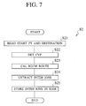
- step S1 the CPU 4 (referred to as control, hereinafter) reads a destination inputted through the operation key board 9.
- control calculates a recommendable vehicle travel route from a start point and the destination by searching various routes in accordance with the well-known searching method (See Japanese Published Unexamined Patent Application No. 62-86499).
- the start point can be inputted through the operation key board 9 or detected on the basis of the GPS signal received by the GPS receiver 10.
- step S3 control counts the number of speed pulses (outputted by the vehicle speed sensor 2) per unit time and detects the vehicle travel speed and further calculates the vehicle travel distance. Further, control calculates a vehicle travel locus on the basis of the calculated vehicle travel distance and the travel azimuth detected by the azimuth sensor 1, and compares with the calculated vehicle travel locus with the road map data stored in the road map memory 3 to specify the current vehicle position CVP. Further, it is also possible to calculate and specify the vehicle travel speed and the current vehicle position CVP on the basis of the GPS signals received by the GPS receiver 10.
- control decides a visual point E and a visual line direction EF both necessary to form an birds-eye view on the basis of the detected vehicle speed and the calculated current vehicle position CVP and in accordance with the procedure shown in Fig. 8.
- control calculates a road map range to be displayed on the display unit 8. In more detail, control decides the range where the trapezoidal range ABCD shown in Fig. 2 is displayed as the road map on the display unit 8.
- step S6 control reads road map data corresponding to the road map range decided in step S5 from the load map memory 3.
- control transforms the road map data read from the road map memory in step S6 into birds-eye view road map data.
- control transforms the road map data in the trapezoidal range ABCD shown in Fig. 2 into image data to be displayed as a road map in the range abcd also shown in Fig. 2.
- step S7 after the image data have been formed, the color of the recommendable route obtained in step S2 is determined so as to be distinguishable from that of the birds-eye view road map data. Further, a vehicle mark indicative of the current vehicle position CVP (obtained in step S3) is also synthesized with the image data (e.g., in the form of an arrow as shown in Figs. 16A and 16B).
- step S8 the image data formed in step S8 are transferred to the V-RAM 7 to display the transformed road map data of the birds-eye view on the display unit 8.
- step S9 control discriminates whether the vehicle travels by a travel distance longer than a predetermined value on the basis of the output signal of the vehicle speed sensor 2 or the GPS signal. If YES, control returns to the step S3 to calculates the visual point E and the visual line direction EF again, and displays again the birds-eye view road map data on the basis of the recalculated results. On the other hand, if NO in step S9, control remains at the same step S9.
- control first reads a start point and a destination point both inputted from the operation key board 9, for instance.
- control detects the current vehicle speed by counting the number of pulses per unit time or measuring the pulse period both outputted by the vehicle speed sensor 2 and further calculates the travel distance by multiplying the detected current speed by the unit time.
- control calculates the vehicle travel locus on the basis of the calculated vehicle travel distance and a vehicle travel azimuth detected by the azimuth sensor 1, and detects the current vehicle position CVP by comparing the obtained distance and the azimuth with the road map data stored in the road map memory 3 (map matching).
- the method of detecting the current position as described above is referred to as an autonomous navigation. However, it is also possible to detect the current vehicle position CVP on the basis of the GPS signal received by the GPS signal receiver 10, as already explained.
- control calculates a recommendable vehicle travel route from the start point to the destination on the road map.
- control extracts specific traffic points (e.g., specific intersections (referred to as guide intersections, hereinafter)) necessary to guide the vehicle along the recommendable route from the road map memory 3, and further stores various information related to the extracted guide intersections in the RAM 6.
- specific traffic points e.g., specific intersections (referred to as guide intersections, hereinafter)
- guide intersections are extracted in this step: since there are many intersections (e.g., intersections with small roads) unnecessary to guide the vehicle along the recommendable route, when the road map is replaced or redisplayed with another road map so often at all the unnecessary intersections, the load of the CPU 4 increases without having no special significance.
- the guide intersections are extracted on the basis of the classification of roads (express highways, national roads, prefecture roads, etc.) crossing the recommendable route, the angles of intersections with other roads, the number of crossing roads at the intersection, etc.
- control stores the guide intersections (specific traffic points) extracted in step S24 above in the RAM 6, ending the procedure.
- step S4 of Fig. 6 The feature of the first embodiment resides in step S4 of Fig. 6. Therefore, only the step of deciding the visual point E and the visual line direction EF executed in step S4 in Fig. 6 will be described in detail hereinbelow with reference to Figs. 8 and 11.
- Fig. 9 shows an example of the visual points E1 and E2 and the visual line length
- is determined always constant, and the horizontal visual line direction angle ⁇ between the horizontal line AA' (upon which the visual line EF is projected) and the x axis is also determined always constant, as shown in Fig. 9.
- the vertical and horizontal visual field angles 2 ⁇ and 2 ⁇ are determined always constant.
- the vertical visual field angles 2 ⁇ and the horizontal visual field angle 2 ⁇ are both kept always constant, irrespective of the visual point E as shown.
- control sets the end position F of the visual line length EF near the current vehicle position CVP obtained by the step S3 in Fig. 6.
- control determines the horizontal visual line direction ⁇ .
- the horizontal visual line direction ⁇ can be set to any of various directions (e.g., the vehicle travel direction detected by the azimuth sensor 1, a direction along which the recommendable route can be displayed over the longest distance, a direction from the current vehicle position to the destination, etc.).
- control determines the magnitude of the visual line length
- k1 x k2 x vehicle speed where k1 and k2 denote a positive constant value, respectively.
- control determines the visual point E on the basis of the visual line end position (current vehicle position) F, the visual line length
- the visual point E is set to E1 when the vehicle speed is low, but to E2 when high. Further, when the visual point is E1, the displayed map range is a trapezoidal range A1-B1-C1-D1; and when the visual point is E2, the displayed map range is a trapezoidal range A2-B2-C2-D2, respectively.
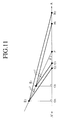
- Fig. 11 shows a view in which the direction AA' shown in Fig. 9 is taken along the abscissa, and the z-axis shown in Fig. 9 is taken along the ordinate.
- the displayed map range is a small range G1-H1; and when the visual point is E2, the displayed map range is a large range G2-H2, respectively. Therefore, when the visual point is E2, a broader road map can be displayed.
- the overlook angle ⁇ from the visual point E is kept constant, and the visual line length
- step S103 in Fig. 8 although the visual line length
- is decided at four stages:
- the second embodiment of the first aspect of the present invention will be described hereinbelow.
- is determined according to the vehicle speed.
- the vertical overlook angle ⁇ is changed according to the vehicle speed.
- the second embodiment is the same as the first embodiment except the step S4 shown in Fig. 6. Therefore, only the step S4 is described with reference to the flowchart shown in Fig. 12.
- between the visual point E and the visual line end position F is kept always constant, and only the vertical overlook angle ⁇ is changed according to the vehicle speed. Further, in this embodiment, the visual line end position F is decided near the current vehicle position CVP on the road map in the same way as with the case of the first embodiment.
- step S201 control sets the end position F of the visual line direction EF near the current vehicle position CVP obtained the step S3 in Fig. 6.
- control determines the horizontal visual line direction angle ⁇ .
- the horizontal visual line direction angle ⁇ can be set to any of various directions in the same way with the case of the first embodiment.
- control determines the visual point E on the basis of the visual line end position (current vehicle position) F, the constant visual line length
- the vertical overlook angle ⁇ is set to ⁇ 3 and therefore the visual point is set to E3, so that the road map range to be displayed is A3-B3-C3-D3.
- the vertical overlook angle ⁇ is set to ⁇ 4 and therefore the visual point is set to E4, so that the road map range to be displayed is A4-B4-C4-D4.
- Fig. 14 shows a view in which the direction AA' shown in Fig. 13 is taken along the abscissa, and the z-axis shown in Fig. 13 is taken along the ordinate.
- the displayed map range is G3-H3; and when the visual point is E4, the displayed map range is G4-H4, respectively. Therefore, as shown in Figs. 13 and 14, the higher the vehicle speed is, the smaller will be the vertical overlook angle ⁇ so that a broader road map can be displayed.
- the distance between the visual point E and the end F of the visual line length EF is always kept constant, and only the vertical overlook angle ⁇ between the axis AA' and the visual line direction EF is changed according to the vehicle speed. Therefore, in practice, the higher the vehicle speed is, the smaller will be the vertical overlook angle ⁇ or the lower the vehicle speed is, the larger will be the vertical overlook angle ⁇ . Accordingly, when the vehicle speed is high, the broader road map can be displayed; and when the vehicle speed is low, the narrower road map near the current vehicle position can be displayed in detail.
- the distance between the visual point E and the visual lie end position F (the current vehicle position CVP) is kept always constant, even if the displayed road map is switched according to the vehicle speed, it is possible to obtain the road maps in roughly the same contraction scale ratio at the current vehicle position, so that the displayed road map is easy to see.
- the second aspect of the vehicle navigation system according to the present invention will be described hereinbelow.
- the feature of the second aspect is to change the horizontal visual line direction ⁇ according to the distance d between the current vehicle position CVP and a specific traffic point (e.g., the nearest intersection along the recommendable travel route).
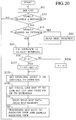
- the CPU 4 executes the birds-eye view forming processing as shown in Fig. 15.
- step S11 control detects the current vehicle position CVP in the same way as in step S2 shown in Fig. 6.
- step S12 control discriminates whether the vehicle travels by a predetermined distance or not on the basis of the sensor pulse outputted by the vehicle speed sensor 2 or the GPS signal. If NO in step S12, control returns to the step S11. If YES, controls proceeds to step S13.
- step S13 control discriminates whether the vehicle passes through the guide intersection or not. If YES, control proceeds to step S14.
- step S14 control reads road map data to the nearest guide intersection in the travel direction from the RAM 6. If NO, control proceeds to the step S15.
- control calculates a distance d between the current vehicle position CVP and the nearest guide intersection.
- step S16 control discriminates whether the distance d to the nearest guide intersection is less than a predetermined distance D or not. If YES, control proceeds to step S17.
- step S17 the horizontal visual line direction ⁇ is decided. That is, control decides the visual point E in the sky opposite to the current vehicle position along the vehicle travel direction (behind the vehicle current position), and further decides the visual line end position F to the nearest guide intersection in such a way that the nearest guide intersection can be seen downward from the decided visual point E in the visual line direction EF.
- the visual line direction angle ⁇ or axis AA' from the x axis is also set to the nearest intersection (not the current vehicle position CVP).
- step S16 control proceeds to step S18, and decides the visual point in the sky opposite to the current vehicle position along the vehicle travel direction (behind the current vehicle position), and further decides the visual line end position F to a point a distance ahead along the recommendable route in such a way that a point by a predetermined distance ahead from the current vehicle position can be seen downward from the decided visual point E in the visual line direction EF.
- step S19 Upon completion of the step S17 or S18, control proceeds to step S19, and reads the road map data within a predetermined road map range from the road map memory 3. That is, the road map data necessary within the range (ABCD in Fig. 2) corresponding to the decided visual point E and the decided visual line direction EF both decided in step 17 or 18 from the road map memory 3.
- step S20 control converts the road map data read in step S19 into data necessary for an birds-eye view road map and displays the converted road map data on the display unit 8.
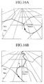
- Fig. 16A an example of the birds-eye view obtained by the processing in step S17
- Fig. 16B an example of the birds-eye view obtained by the processing in step S18
- the guide intersection is displayed substantially vertically at roughly the center of the display as shown in Fig. 16A.
- a point P a predetermined distance ahead from the current vehicle position (an arrow) along the recommendable route is displayed at roughly the central portion of the display as shown in Fig. 16B.
- the point P is not actually shown on the display unit 8.
- the vehicle current position is shown at roughly the same middle lower side portion of the display, irrespective of the distance d to the guide intersection.
- the displayed map range shown in the display unit 8 is roughly the same, irrespective of the distance to the guide intersection.
- the driver when the distance d from the current vehicle position to the next guide intersection in the vehicle travel direction is short, since the forward direction (in which the current position and the next guide intersection are connected to each other) is displayed substantially vertically at roughly the central portion on the display unit 8, the driver can well see and know the next guide intersection more securely.
- the forward direction in which the current position and a frontward position a predetermined distance ahead from the current position along the recommendable route
- the driver can well see and know the mutual positional relationship between the current position and the frontward position along the recommendable route.
- the above-mentioned predetermined distance ahead from the current vehicle position is decided relatively long, it is possible to display the recommendable route over a long distance on the display unit 8.
- the current vehicle position and the road map range are both always displayed in the same way, irrespective of the distance to the next guide intersection, whenever the birds-eye view road map is replaced with a new one, the driver can securely see the current vehicle position without losing the sight of the current vehicle position on the display unit 8.
- the horizontal visual line direction ⁇ is set to the next guide intersection to display the next guide intersection vertically on the road map.
- the horizontal visual line direction ⁇ is set to the vehicle travel direction to display the vehicle travel direction vertically on the road map.
- the second embodiment is basically the same as with the case of the first embodiment, except the birds-eye view forming processing executed in step S57 in Fig. 17.
- step S57 the vertical visual line angle ⁇ is decided. That is, control decides the visual point E in the sky opposite to the current vehicle position along the vehicle travel direction (behind the vehicle current position), and further decides the visual line end position F to a point a predetermined distance ahead in the travel direction in such a way that the current vehicle travel direction can be seen downward from the decided visual point E in the visual line direction EF.
- the visual line direction angle ⁇ or axis AA' from the x axis (See Fig. 9) is set to the vehicle travel direction (not the nearest intersection). Accordingly, the road map ahead of the current vehicle position along the vehicle travel direction can be displayed vertically on the display unit 8.
- the driver when the distance from the current vehicle position to the nearest guide intersection along the vehicle travel direction is short, since the vehicle travel direction can be displayed vertically on the display unit 8, the driver can well see and know the next guide intersection more securely, thus preventing the vehicle from being deviated from the recommendable route.
- the vertical overlook limit angle ⁇ is determined according to the distance d between the current vehicle position and the next guide intersection, and the vertical overlook angle ⁇ is determined within the vertical overlook limit angle ⁇ in such a way that the recommendable route can be displayed over the longest distance.
- the third embodiment is basically the same as with the case of the first embodiment, except the birds-eye view forming processing executed in steps S106 to S109 in Fig. 18.
- the vertical overlook limit angle ⁇ implies an maximum angle ⁇ max obtained when the vertical overlook angle ⁇ can be changed from the vehicle travel direction.
- an appropriate vertical overlook angle ⁇ can be decided within the vertical overlook limit angle ⁇ in accordance with the following processing:
- the vertical overlook limit angle ⁇ increases with increasing distance d to the guide intersection. In other words, since the vertical overlook limit angle ⁇ increases with increasing distance d between the current vehicle position and the next guide intersection, the selective range of the vertical overlook angle is increased.
- control selects several vertical overlook angles ⁇ 1 to ⁇ m (0 ⁇ ⁇ 1 ⁇ ⁇ 2 .. ⁇ ⁇ m) within the vertical overlook limit angle ⁇ .
- control forms birds-eye view road maps at the selected vertical overlook angles ⁇ 1 to ⁇ m, and calculates the recommendable route distances in the respective calculated birds-eye view road maps.
- control selects a vertical overlook angle ⁇ at which the longest recommendable route distance can be displayed, and decides this vertical overlook angle ⁇ as the visual line direction EF, to display the recommendable route over the longest distance.
- control executes the same processing as shown in Fig. 15 to display the formed birds-eye view on the display unit 8.
- the selection limit range ⁇ of the vertical overlook angle ⁇ is changed according to the distance d between the current vehicle position and the nest guide intersection.
- the selection range ⁇ of the visual direction can be narrowed, it is possible to display the guide intersection more securely on the display unit 8.
- the selection range ⁇ of the visual direction can be widened, it is possible to select the visual direction in such a way that the recommendable route can be display over the long distance on the display unit 8.
- the fourth embodiment of the second aspect according to the present invention will be described.
- the visual point E (the horizontal distance between the visual point (x) and the current vehicle position is changed according to the distance d between the current vehicle position and the next intersection. Therefore, the map range or the map contraction scale ratio in the vicinity of the current vehicle position can be changed freely according to the distance to the next guide intersection.
- This fourth embodiment of the second aspect is basically the same as the first embodiment of the first aspect described with reference to Figs. 8 to 11, except that the visual point E is changed according to the distance d to the next intersection (not according to the vehicle speed).
- step S16 control proceeds to step S208, and sets the distance L between the visual point E and the current vehicle position CVP to L0.
- step S209 sets the visual line end position F on a line obtained when the current vehicle position is connected to the next guide intersection.
- the displayed load map range A1-B1-C1-D1 is small as shown.
- the displayed load map range A2-B2-C2-D2 is larger than that obtained from the visual point E1.
- steps S19 and S20 the road map of birds-eye view is formed in the same way as with the case of the other embodiments.
- the fifth embodiment of the second aspect according to the present invention will be described.
- the visual point height is changed according to the distance d between the current vehicle position and the next intersection, without changing the visual line length EF. Therefore, the map range or the map contraction scale ratio in the vicinity of the current vehicle position can be changed freely according to the distance to the next guide intersection.
- This fifth embodiment of the second aspect is basically the same as the second embodiment of the first aspect described with reference to Figs. 12 to 14, except that the visual point E is changed according to the distance d to the next intersection (not according to the vehicle speed).
- step S16 control proceeds to step 5158, and sets the vertical overlook angle ⁇ to ⁇ 0.
- step S159 sets the vertical overlook angle ⁇ according to the distance to the next intersection.
- the height of the visual point E can be changed according to the distance d to the next intersection.
- step S160 sets the visual line end position F on a line obtained when the current vehicle position is connected to the next guide intersection or an extension thereof. Owing to the step S159, when the distance d to the next intersection is small, since the vertical overlook angle ⁇ 4 is large, the visual point E4 is high as shown in Fig. 13, so that the displayed load map range A4-B4-C4-D4 is small as shown.
- steps S19 and S20 the road map of birds-eye view is formed in the same way as with the case of the other embodiments.
- the height of the visual point is changed according to the distance between the current vehicle position and the next guide intersection, so that the road map in the vicinity of the current vehicle position can be displayed at almost the same contraction scale ratio, irrespective of the distance to the next guide intersection.
- the guide intersection and the vicinity thereof can be displayed in an enlarge scale.
- the road map can be displayed at a relatively wide range toward the destination.
- the visual point and the visual direction are both determined on the basis of the distance between the current vehicle position and the nearest guide intersection. Without being limited only thereto, it is possible to change the visual point and the visual direction on the basis of the distance between the current vehicle position and another guide intersection.
- the guide intersections are determined on the basis of the intersection angles between two or more roads, and the visual point and visual line direction are determined on the basis of the next guide intersection.
- a point e.g., ground mark
- any distinguishable key points or second or after intersections ahead of the current vehicle position can be selected as the guide intersection.
- a select switch for selecting desirable one of the various embodiments in order to control the visual point and the visual line direction, when the distance to the next guide intersection is short.
- the birds-eye view road maps of various visual points and various contraction scale ratios can be displayed appropriately according to the vehicle speed or the distance between the current vehicle position and a specific traffic point (e.g., the nearest intersection), the driver can see the road map under the best conditions at all times.
Landscapes
- Engineering & Computer Science (AREA)
- Radar, Positioning & Navigation (AREA)
- Remote Sensing (AREA)
- Physics & Mathematics (AREA)
- Automation & Control Theory (AREA)
- General Physics & Mathematics (AREA)
- Theoretical Computer Science (AREA)
- Computing Systems (AREA)
- Geometry (AREA)
- Computer Graphics (AREA)
- Navigation (AREA)
Applications Claiming Priority (6)
| Application Number | Priority Date | Filing Date | Title |
|---|---|---|---|
| JP7735994A JP3240820B2 (ja) | 1994-04-15 | 1994-04-15 | 車両用経路誘導装置 |
| JP77359/94 | 1994-04-15 | ||
| JP7735994 | 1994-04-15 | ||
| JP17531994A JP3360425B2 (ja) | 1994-07-27 | 1994-07-27 | 車両用ナビゲーション装置 |
| JP175319/94 | 1994-07-27 | ||
| JP17531994 | 1994-07-27 |
Publications (2)
| Publication Number | Publication Date |
|---|---|
| EP0678731A1 true EP0678731A1 (fr) | 1995-10-25 |
| EP0678731B1 EP0678731B1 (fr) | 1999-06-30 |
Family
ID=26418452
Family Applications (1)
| Application Number | Title | Priority Date | Filing Date |
|---|---|---|---|
| EP95105194A Expired - Lifetime EP0678731B1 (fr) | 1994-04-15 | 1995-04-06 | Système de navigation pour véhicule |
Country Status (3)
| Country | Link |
|---|---|
| US (1) | US5732385A (fr) |
| EP (1) | EP0678731B1 (fr) |
| DE (1) | DE69510493T2 (fr) |
Cited By (15)
| Publication number | Priority date | Publication date | Assignee | Title |
|---|---|---|---|---|
| EP0803706A3 (fr) * | 1996-04-26 | 1998-12-23 | Pioneer Electronic Corporation | Appareil de navigation avec fonction d'affichage de changement de forme |
| EP0738876A3 (fr) * | 1995-04-20 | 1999-02-10 | Hitachi, Ltd. | Dispositif d'affichage d'une carte |
| EP0841537A3 (fr) * | 1996-11-07 | 1999-10-27 | Xanavi Informatics Corporation | Méthode et dispositif pour afficher une carte de navigation |
| WO2000052664A1 (fr) * | 1999-03-04 | 2000-09-08 | Mannesmann Vdo Ag | Procede de navigation pour vehicule |
| EP1004850A4 (fr) * | 1998-06-12 | 2002-06-19 | Mitsubishi Electric Corp | Appareil de navigation |
| DE10141507A1 (de) * | 2001-08-24 | 2003-03-13 | Audi Ag | Vorrichtung zur Projektion von Navigationsdaten |
| EP1463014A3 (fr) * | 2003-03-25 | 2004-10-27 | Robert Bosch Gmbh | Dispositif de navigation pour guider un véhicule à une destination |
| WO2004061549A3 (fr) * | 2003-01-07 | 2005-03-24 | Sony Computer Entertainment Inc | Procede et appareil de generation d'images |
| EP1650533A1 (fr) * | 2004-10-20 | 2006-04-26 | France Telecom | Procédé de sélection de points remarquables dans un itinéraire |
| EP2026038A3 (fr) * | 2007-08-14 | 2010-08-04 | Navigon AG | Procédé pour changer l'échelle de la représentation d'une carte dans un système de navigation |
| WO2011095853A1 (fr) * | 2010-02-05 | 2011-08-11 | Sony Ericsson Mobile Communications Ab | Regulation de vitesse de navigation parmi des articles affiches et leur angle d'inclinaison sensible a la pression appliquee par un utilisateur |
| US8751156B2 (en) | 2004-06-30 | 2014-06-10 | HERE North America LLC | Method of operating a navigation system using images |
| EP1614997B1 (fr) * | 2004-06-30 | 2015-02-18 | HERE North America, LLC | Procédé de pilotage d'un système de navigation utilisant des images. |
| US9638539B2 (en) | 2011-06-30 | 2017-05-02 | Tomtom Navigation B.V. | Navigation methods and apparatus |
| US20220221291A1 (en) * | 2019-05-08 | 2022-07-14 | Daimler Ag | Method and device for locating a vehicle |
Families Citing this family (63)
| Publication number | Priority date | Publication date | Assignee | Title |
|---|---|---|---|---|
| US6654014B2 (en) * | 1995-04-20 | 2003-11-25 | Yoshinori Endo | Bird's-eye view forming method, map display apparatus and navigation system |
| JPH08335038A (ja) * | 1995-06-09 | 1996-12-17 | Zanavy Informatics:Kk | 車両用地図表示装置 |
| US5964810A (en) * | 1995-06-09 | 1999-10-12 | Xanavi Informatics Corporation | Map display apparatus |
| JP3353581B2 (ja) * | 1995-12-26 | 2002-12-03 | 日産自動車株式会社 | 鳥瞰図表示ナビゲーション装置 |
| JPH09230783A (ja) * | 1996-02-26 | 1997-09-05 | Nissan Motor Co Ltd | 地図表示装置 |
| US5884213A (en) * | 1996-03-22 | 1999-03-16 | Johnson Worldwide Asociates, Inc. | System for controlling navigation of a fishing boat |
| US5936553A (en) * | 1997-02-28 | 1999-08-10 | Garmin Corporation | Navigation device and method for displaying navigation information in a visual perspective view |
| US6345232B1 (en) | 1997-04-10 | 2002-02-05 | Urban H. D. Lynch | Determining aircraft position and attitude using GPS position data |
| US6747680B1 (en) * | 1999-12-13 | 2004-06-08 | Microsoft Corporation | Speed-dependent automatic zooming interface |
| DE59809476D1 (de) * | 1997-11-03 | 2003-10-09 | Volkswagen Ag | Autonomes Fahrzeug und Verfahren zur Steuerung eines autonomen Fahrzeuges |
| US6611753B1 (en) * | 1998-04-17 | 2003-08-26 | Magellan Dis, Inc. | 3-dimensional intersection display for vehicle navigation system |
| JP2000305452A (ja) * | 1999-04-21 | 2000-11-02 | Sony Corp | 電子地図装置および電子地図の表示方法 |
| JP3805923B2 (ja) * | 1999-04-28 | 2006-08-09 | 本田技研工業株式会社 | 車両通信装置 |
| WO2000071974A1 (fr) * | 1999-05-19 | 2000-11-30 | Mitsubishi Denki Kabushiki Kaisha | Dispositif de navigation automobile |
| US6430501B1 (en) | 2000-01-19 | 2002-08-06 | Magellan Dis, Inc. | Navigation system with route indicators |
| DE10010310B4 (de) * | 2000-03-06 | 2009-06-10 | Harman Becker Automotive Systems Gmbh | Verfahren und Vorrichtung zur Darstellung eines geografischen Bildes auf einem Bildschirm |
| JP3367523B2 (ja) * | 2000-03-14 | 2003-01-14 | アイシン・エィ・ダブリュ株式会社 | 道路地図表示装置 |
| JP2001264099A (ja) | 2000-03-15 | 2001-09-26 | Honda Motor Co Ltd | 車両用ナビゲーション装置 |
| DE10027516A1 (de) * | 2000-06-06 | 2001-12-13 | Bosch Gmbh Robert | Verfahren zur Zoom-Einstellung eines Kartendarstellungssystems eines Fahrzeugs |
| US7668648B2 (en) * | 2001-03-06 | 2010-02-23 | Harman Becker Automotive Systems Gmbh | Motor vehicle navigation system |
| JP2002311821A (ja) * | 2001-04-13 | 2002-10-25 | Mitsubishi Electric Corp | ナビゲーションにおける地図表示方法およびナビゲーション装置 |
| JP4453796B2 (ja) * | 2001-05-29 | 2010-04-21 | 日本電気株式会社 | 位置情報表示端末の地図表示方法およびそのシステム |
| US6853912B2 (en) * | 2002-08-10 | 2005-02-08 | Alpine Electronics, Inc. | Display method and apparatus for navigation system |
| WO2005020186A1 (fr) * | 2003-08-22 | 2005-03-03 | Hitachi, Ltd. | Procede d'affichage d'un plan |
| JP4676684B2 (ja) * | 2003-08-26 | 2011-04-27 | クラリオン株式会社 | 車載情報端末 |
| US7327349B2 (en) * | 2004-03-02 | 2008-02-05 | Microsoft Corporation | Advanced navigation techniques for portable devices |
| JP4508728B2 (ja) * | 2004-06-07 | 2010-07-21 | アルパイン株式会社 | 車載用電子機器およびその機器におけるディジタル放送の表示方法 |
| US7376510B1 (en) * | 2004-11-05 | 2008-05-20 | Navteq North America, Llc | Map display for a navigation system |
| US7908080B2 (en) | 2004-12-31 | 2011-03-15 | Google Inc. | Transportation routing |
| DE102006002741A1 (de) * | 2006-01-20 | 2007-08-02 | Robert Bosch Gmbh | Verfahren zur Darstellung eines Kartenausschnitts auf einer Anzeige eines Fahrerinformationssystems und Fahrerinformationssystem mit Kartendarstellung |
| US7743056B2 (en) * | 2006-03-31 | 2010-06-22 | Aol Inc. | Identifying a result responsive to a current location of a client device |
| US7869941B2 (en) | 2006-12-29 | 2011-01-11 | Aol Inc. | Meeting notification and modification service |
| US8712810B2 (en) | 2006-12-29 | 2014-04-29 | Facebook, Inc. | Reserving a time block in a calendar application to account for a travel time between geographic locations of appointments |
| JP4420034B2 (ja) * | 2007-02-01 | 2010-02-24 | 株式会社デンソー | 車両用地図表示装置 |
| JP2008216205A (ja) * | 2007-03-07 | 2008-09-18 | Fujitsu Ltd | 車載ナビゲーション装置 |
| KR100837345B1 (ko) * | 2007-06-25 | 2008-06-12 | (주)엠앤소프트 | 차량단말기에서의 교차로 확대도 표출 방법 |
| JP2009036571A (ja) * | 2007-07-31 | 2009-02-19 | Toshiba Corp | 可視光通信システムを利用した位置測定システム、位置測定装置及び位置測定方法 |
| JP4548460B2 (ja) * | 2007-08-31 | 2010-09-22 | 株式会社デンソー | ナビゲーション装置 |
| US8554475B2 (en) | 2007-10-01 | 2013-10-08 | Mitac International Corporation | Static and dynamic contours |
| JP2009103521A (ja) * | 2007-10-22 | 2009-05-14 | Fujitsu Ten Ltd | ナビゲーションシステム、携帯端末装置および車載装置 |
| JP4915343B2 (ja) * | 2007-12-21 | 2012-04-11 | ソニー株式会社 | 電子機器装置及びナビゲーション方法 |
| US9062982B2 (en) * | 2008-12-15 | 2015-06-23 | Blackberry Limited | Pre-loading waypoint data |
| US20100324818A1 (en) * | 2009-06-19 | 2010-12-23 | Gm Global Technology Operations, Inc. | Presentation of navigation instructions using variable content, context and/or formatting |
| KR101231510B1 (ko) * | 2010-10-11 | 2013-02-07 | 현대자동차주식회사 | 운전자 주시방향 연동 전방충돌 위험경보 시스템, 그 방법 및 그를 이용한 차량 |
| KR101779966B1 (ko) * | 2010-12-13 | 2017-10-10 | 한국전자통신연구원 | 위치서비스 제공방법 및 이동 단말기 |
| TW201237451A (en) * | 2011-03-04 | 2012-09-16 | Hon Hai Prec Ind Co Ltd | Positioning and navigating device |
| USD719973S1 (en) * | 2012-06-06 | 2014-12-23 | Apple Inc. | Display screen or portion thereof with graphical user interface |
| USD709915S1 (en) | 2012-06-11 | 2014-07-29 | Apple Inc. | Display screen or portion thereof with graphical user interface |
| USD750110S1 (en) * | 2012-11-08 | 2016-02-23 | Uber Technologies, Inc. | Display screen of a computing device with a computer-generated electronic panel for providing information of a service |
| USD735214S1 (en) | 2012-11-30 | 2015-07-28 | Google Inc. | Display screen or portion thereof with graphical user interface |
| US8676431B1 (en) | 2013-03-12 | 2014-03-18 | Google Inc. | User interface for displaying object-based indications in an autonomous driving system |
| USD750663S1 (en) | 2013-03-12 | 2016-03-01 | Google Inc. | Display screen or a portion thereof with graphical user interface |
| USD754189S1 (en) | 2013-03-13 | 2016-04-19 | Google Inc. | Display screen or portion thereof with graphical user interface |
| USD754190S1 (en) | 2013-03-13 | 2016-04-19 | Google Inc. | Display screen or portion thereof with graphical user interface |
| US9267810B2 (en) * | 2013-07-12 | 2016-02-23 | Google Inc. | Systems and methods for displaying navigational information |
| USD795268S1 (en) | 2015-02-27 | 2017-08-22 | Uber Technologies, Inc. | Display screen computing device with graphical user interface |
| USD775636S1 (en) | 2015-02-27 | 2017-01-03 | Uber Technologies, Inc. | Display screen for a computing device with graphical user interface |
| JP6122893B2 (ja) * | 2015-03-19 | 2017-04-26 | ヤフー株式会社 | ナビゲーション装置、方法及びプログラム |
| JP1553720S (fr) * | 2015-10-28 | 2016-07-11 | ||
| JP6705368B2 (ja) | 2016-12-06 | 2020-06-03 | トヨタ自動車株式会社 | 自動運転装置 |
| CN111664862B (zh) * | 2019-03-06 | 2022-07-26 | 北京嘀嘀无限科技发展有限公司 | 一种显示比例调整方法和系统 |
| DE112020006380T5 (de) * | 2019-12-27 | 2022-11-17 | Nippon Seiki Co., Ltd. | Navigationsvorrichtung, Steuerungsverfahren für die Navigationsvorrichtung, Steuerprogramm für die Navigationsvorrichtung |
| CN115145671B (zh) * | 2022-06-30 | 2026-02-10 | 腾讯科技(深圳)有限公司 | 车辆导航方法、装置、设备、存储介质和计算机程序产品 |
Citations (6)
| Publication number | Priority date | Publication date | Assignee | Title |
|---|---|---|---|---|
| JPH01161111A (ja) * | 1987-12-18 | 1989-06-23 | Mitsubishi Electric Corp | 移動体用ナビゲーシヨン装置 |
| DE3842179A1 (de) * | 1987-12-15 | 1989-06-29 | Mitsubishi Electric Corp | Navigationsvorrichtung fuer sich bewegende objekte |
| FR2634707A1 (fr) * | 1988-07-28 | 1990-02-02 | Peugeot | Dispositif d'aide a la navigation d'un vehicule notamment automobile |
| EP0378271A1 (fr) * | 1989-01-11 | 1990-07-18 | Koninklijke Philips Electronics N.V. | Procédé pour visualiser une partie d'une carte topographique et dispositif convenant pour un tel procédé |
| JPH03225391A (ja) * | 1990-01-31 | 1991-10-04 | Alpine Electron Inc | 地図描画方法 |
| JPH04219783A (ja) * | 1990-12-20 | 1992-08-10 | Sumitomo Electric Ind Ltd | 車載ナビゲーション装置 |
Family Cites Families (6)
| Publication number | Priority date | Publication date | Assignee | Title |
|---|---|---|---|---|
| JPH069079B2 (ja) * | 1985-10-12 | 1994-02-02 | 日産自動車株式会社 | 車両用経路案内装置 |
| EP0346491A4 (en) * | 1987-12-28 | 1992-08-19 | Aisin Aw Co., Ltd. | A display unit of navigation system |
| JPH0261690A (ja) * | 1988-08-26 | 1990-03-01 | Daihatsu Motor Co Ltd | ナビゲーション用地図の表示方法 |
| JPH076802B2 (ja) * | 1988-11-11 | 1995-01-30 | 本田技研工業株式会社 | 移動体の現在位置表示装置 |
| JP3378031B2 (ja) * | 1992-08-19 | 2003-02-17 | アイシン・エィ・ダブリュ株式会社 | 車両用ナビゲーション装置 |
| FR2734707B1 (fr) * | 1995-05-30 | 1997-08-29 | Guedj Leon | Equipement chirurgical d'implantologie dentaire et elements, implant dentaire et instruments de forage, constitutifs |
-
1995
- 1995-04-06 DE DE69510493T patent/DE69510493T2/de not_active Expired - Lifetime
- 1995-04-06 EP EP95105194A patent/EP0678731B1/fr not_active Expired - Lifetime
- 1995-04-11 US US08/420,992 patent/US5732385A/en not_active Expired - Lifetime
Patent Citations (6)
| Publication number | Priority date | Publication date | Assignee | Title |
|---|---|---|---|---|
| DE3842179A1 (de) * | 1987-12-15 | 1989-06-29 | Mitsubishi Electric Corp | Navigationsvorrichtung fuer sich bewegende objekte |
| JPH01161111A (ja) * | 1987-12-18 | 1989-06-23 | Mitsubishi Electric Corp | 移動体用ナビゲーシヨン装置 |
| FR2634707A1 (fr) * | 1988-07-28 | 1990-02-02 | Peugeot | Dispositif d'aide a la navigation d'un vehicule notamment automobile |
| EP0378271A1 (fr) * | 1989-01-11 | 1990-07-18 | Koninklijke Philips Electronics N.V. | Procédé pour visualiser une partie d'une carte topographique et dispositif convenant pour un tel procédé |
| JPH03225391A (ja) * | 1990-01-31 | 1991-10-04 | Alpine Electron Inc | 地図描画方法 |
| JPH04219783A (ja) * | 1990-12-20 | 1992-08-10 | Sumitomo Electric Ind Ltd | 車載ナビゲーション装置 |
Non-Patent Citations (3)
| Title |
|---|
| PATENT ABSTRACTS OF JAPAN vol. 13, no. 428 (P - 936) 25 September 1989 (1989-09-25) * |
| PATENT ABSTRACTS OF JAPAN vol. 16, no. 3 (P - 1294) 7 January 1992 (1992-01-07) * |
| PATENT ABSTRACTS OF JAPAN vol. 16, no. 568 (P - 1458) 9 December 1992 (1992-12-09) * |
Cited By (25)
| Publication number | Priority date | Publication date | Assignee | Title |
|---|---|---|---|---|
| US6603407B2 (en) | 1995-04-20 | 2003-08-05 | Hitachi, Ltd. | Map display apparatus |
| EP0738876A3 (fr) * | 1995-04-20 | 1999-02-10 | Hitachi, Ltd. | Dispositif d'affichage d'une carte |
| US6278383B1 (en) | 1995-04-20 | 2001-08-21 | Hitachi, Ltd. | Map display apparatus |
| US6756919B2 (en) | 1995-04-20 | 2004-06-29 | Hitachi, Ltd. | Map display apparatus |
| EP0803706A3 (fr) * | 1996-04-26 | 1998-12-23 | Pioneer Electronic Corporation | Appareil de navigation avec fonction d'affichage de changement de forme |
| EP0841537A3 (fr) * | 1996-11-07 | 1999-10-27 | Xanavi Informatics Corporation | Méthode et dispositif pour afficher une carte de navigation |
| US6175802B1 (en) | 1996-11-07 | 2001-01-16 | Xanavi Informatics Corporation | Map displaying method and apparatus, and navigation system having the map displaying apparatus |
| EP1004850A4 (fr) * | 1998-06-12 | 2002-06-19 | Mitsubishi Electric Corp | Appareil de navigation |
| US6473693B1 (en) | 1998-06-12 | 2002-10-29 | Mitsubishi Denki Kabushiki Kaisha | Navigation device for displaying an approaching intersection |
| WO2000052664A1 (fr) * | 1999-03-04 | 2000-09-08 | Mannesmann Vdo Ag | Procede de navigation pour vehicule |
| DE10141507C2 (de) * | 2001-08-24 | 2003-06-18 | Audi Ag | Vorrichtung zur Projektion von Navigationsdaten |
| DE10141507A1 (de) * | 2001-08-24 | 2003-03-13 | Audi Ag | Vorrichtung zur Projektion von Navigationsdaten |
| US7397971B2 (en) | 2003-01-07 | 2008-07-08 | Sony Computer Entertainment Inc. | Image generating method and image generating apparatus |
| WO2004061549A3 (fr) * | 2003-01-07 | 2005-03-24 | Sony Computer Entertainment Inc | Procede et appareil de generation d'images |
| EP1463014A3 (fr) * | 2003-03-25 | 2004-10-27 | Robert Bosch Gmbh | Dispositif de navigation pour guider un véhicule à une destination |
| US8751156B2 (en) | 2004-06-30 | 2014-06-10 | HERE North America LLC | Method of operating a navigation system using images |
| EP1614997B1 (fr) * | 2004-06-30 | 2015-02-18 | HERE North America, LLC | Procédé de pilotage d'un système de navigation utilisant des images. |
| US10281293B2 (en) | 2004-06-30 | 2019-05-07 | Here Global B.V. | Method of operating a navigation system using images |
| EP1650533A1 (fr) * | 2004-10-20 | 2006-04-26 | France Telecom | Procédé de sélection de points remarquables dans un itinéraire |
| EP2026038A3 (fr) * | 2007-08-14 | 2010-08-04 | Navigon AG | Procédé pour changer l'échelle de la représentation d'une carte dans un système de navigation |
| US8237744B2 (en) | 2007-08-14 | 2012-08-07 | Garmin Würzburg GmbH | Method for changing scale in a navigation device |
| WO2011095853A1 (fr) * | 2010-02-05 | 2011-08-11 | Sony Ericsson Mobile Communications Ab | Regulation de vitesse de navigation parmi des articles affiches et leur angle d'inclinaison sensible a la pression appliquee par un utilisateur |
| US9638539B2 (en) | 2011-06-30 | 2017-05-02 | Tomtom Navigation B.V. | Navigation methods and apparatus |
| US20220221291A1 (en) * | 2019-05-08 | 2022-07-14 | Daimler Ag | Method and device for locating a vehicle |
| US11851069B2 (en) * | 2019-05-08 | 2023-12-26 | Mercedes-Benz Group AG | Method and device for locating a vehicle |
Also Published As
| Publication number | Publication date |
|---|---|
| DE69510493D1 (de) | 1999-08-05 |
| US5732385A (en) | 1998-03-24 |
| EP0678731B1 (fr) | 1999-06-30 |
| DE69510493T2 (de) | 1999-10-28 |
Similar Documents
| Publication | Publication Date | Title |
|---|---|---|
| EP0678731B1 (fr) | Système de navigation pour véhicule | |
| EP0738874B1 (fr) | Dispositif d'affichage pour navigation avec vue à vol d'oiseau | |
| US6760027B2 (en) | Bird's-eye view forming method, map display apparatus and navigation system | |
| EP0660290B1 (fr) | Dispositif et procédé de navigation d'un véhicule vers sa destination utilisant une unité de visualisation | |
| JP3483672B2 (ja) | ナビゲーション装置 | |
| US5459667A (en) | Navigation apparatus for informing vehicle driver of information regarding travel route | |
| US6487496B2 (en) | Mobile navigation apparatus with route deviation indication | |
| KR100766677B1 (ko) | 항법 장치 | |
| US20030130790A1 (en) | In-vehicle navigation apparatus | |
| JP2000283781A5 (fr) | ||
| JP2653282B2 (ja) | 車両用道路情報表示装置 | |
| JP3492887B2 (ja) | 3次元景観図表示方法 | |
| JP3222616B2 (ja) | 車載用ナビゲーション装置 | |
| JP2882251B2 (ja) | 経路誘導装置 | |
| JPH08201093A (ja) | ナビゲーション装置 | |
| JP2009014555A (ja) | ナビゲーション装置、ナビゲーション方法及びナビゲーションプログラム | |
| JP3864729B2 (ja) | 車両用離脱判定装置 | |
| JP2795206B2 (ja) | 経路案内装置 | |
| JP3025802B2 (ja) | 経路誘導装置 | |
| JP3460513B2 (ja) | 車載ディスプレイ制御装置 | |
| JP3417413B2 (ja) | ナビゲーション装置 | |
| JP3374850B2 (ja) | ナビゲーション装置 | |
| JP2002013935A (ja) | ナビゲーション装置 | |
| JP3097377B2 (ja) | 車両用経路誘導装置 | |
| JPH06307884A (ja) | 経路誘導装置 |
Legal Events
| Date | Code | Title | Description |
|---|---|---|---|
| PUAI | Public reference made under article 153(3) epc to a published international application that has entered the european phase |
Free format text: ORIGINAL CODE: 0009012 |
|
| 17P | Request for examination filed |
Effective date: 19950406 |
|
| AK | Designated contracting states |
Kind code of ref document: A1 Designated state(s): DE FR GB |
|
| 17Q | First examination report despatched |
Effective date: 19970707 |
|
| GRAG | Despatch of communication of intention to grant |
Free format text: ORIGINAL CODE: EPIDOS AGRA |
|
| GRAG | Despatch of communication of intention to grant |
Free format text: ORIGINAL CODE: EPIDOS AGRA |
|
| GRAH | Despatch of communication of intention to grant a patent |
Free format text: ORIGINAL CODE: EPIDOS IGRA |
|
| GRAH | Despatch of communication of intention to grant a patent |
Free format text: ORIGINAL CODE: EPIDOS IGRA |
|
| GRAA | (expected) grant |
Free format text: ORIGINAL CODE: 0009210 |
|
| AK | Designated contracting states |
Kind code of ref document: B1 Designated state(s): DE FR GB |
|
| REF | Corresponds to: |
Ref document number: 69510493 Country of ref document: DE Date of ref document: 19990805 |
|
| ET | Fr: translation filed | ||
| PLBE | No opposition filed within time limit |
Free format text: ORIGINAL CODE: 0009261 |
|
| STAA | Information on the status of an ep patent application or granted ep patent |
Free format text: STATUS: NO OPPOSITION FILED WITHIN TIME LIMIT |
|
| 26N | No opposition filed | ||
| REG | Reference to a national code |
Ref country code: GB Ref legal event code: IF02 |
|
| PGFP | Annual fee paid to national office [announced via postgrant information from national office to epo] |
Ref country code: GB Payment date: 20100325 Year of fee payment: 16 |
|
| PGFP | Annual fee paid to national office [announced via postgrant information from national office to epo] |
Ref country code: FR Payment date: 20100521 Year of fee payment: 16 |
|
| PGFP | Annual fee paid to national office [announced via postgrant information from national office to epo] |
Ref country code: DE Payment date: 20100430 Year of fee payment: 16 |
|
| REG | Reference to a national code |
Ref country code: DE Ref legal event code: R119 Ref document number: 69510493 Country of ref document: DE |
|
| REG | Reference to a national code |
Ref country code: DE Ref legal event code: R119 Ref document number: 69510493 Country of ref document: DE |
|
| GBPC | Gb: european patent ceased through non-payment of renewal fee |
Effective date: 20110406 |
|
| REG | Reference to a national code |
Ref country code: FR Ref legal event code: ST Effective date: 20111230 |
|
| PG25 | Lapsed in a contracting state [announced via postgrant information from national office to epo] |
Ref country code: FR Free format text: LAPSE BECAUSE OF NON-PAYMENT OF DUE FEES Effective date: 20110502 |
|
| PG25 | Lapsed in a contracting state [announced via postgrant information from national office to epo] |
Ref country code: GB Free format text: LAPSE BECAUSE OF NON-PAYMENT OF DUE FEES Effective date: 20110406 |
|
| PG25 | Lapsed in a contracting state [announced via postgrant information from national office to epo] |
Ref country code: DE Free format text: LAPSE BECAUSE OF NON-PAYMENT OF DUE FEES Effective date: 20111031 |