EP0678858A2 - Détection des bords d'un support magnétique - Google Patents
Détection des bords d'un support magnétique Download PDFInfo
- Publication number
- EP0678858A2 EP0678858A2 EP95302613A EP95302613A EP0678858A2 EP 0678858 A2 EP0678858 A2 EP 0678858A2 EP 95302613 A EP95302613 A EP 95302613A EP 95302613 A EP95302613 A EP 95302613A EP 0678858 A2 EP0678858 A2 EP 0678858A2
- Authority
- EP
- European Patent Office
- Prior art keywords
- transducer
- tape
- medium
- noise signal
- noise
- Prior art date
- Legal status (The legal status is an assumption and is not a legal conclusion. Google has not performed a legal analysis and makes no representation as to the accuracy of the status listed.)
- Withdrawn
Links
- 238000001514 detection method Methods 0.000 title 1
- 238000000034 method Methods 0.000 claims description 8
- 230000004044 response Effects 0.000 claims description 8
- 238000013500 data storage Methods 0.000 claims description 6
- 238000010438 heat treatment Methods 0.000 abstract description 4
- 238000012545 processing Methods 0.000 abstract description 3
- 239000010409 thin film Substances 0.000 description 4
- 230000008859 change Effects 0.000 description 3
- 238000010586 diagram Methods 0.000 description 2
- 230000004907 flux Effects 0.000 description 2
- 238000012986 modification Methods 0.000 description 2
- 230000004048 modification Effects 0.000 description 2
- 238000001228 spectrum Methods 0.000 description 2
- 229910001030 Iron–nickel alloy Inorganic materials 0.000 description 1
- 230000003213 activating effect Effects 0.000 description 1
- 230000008901 benefit Effects 0.000 description 1
- 238000006073 displacement reaction Methods 0.000 description 1
- 238000001914 filtration Methods 0.000 description 1
- 230000010354 integration Effects 0.000 description 1
- 238000005259 measurement Methods 0.000 description 1
- 239000002923 metal particle Substances 0.000 description 1
- 229910000889 permalloy Inorganic materials 0.000 description 1
- 235000019592 roughness Nutrition 0.000 description 1
- 238000012360 testing method Methods 0.000 description 1
Images


Classifications
-
- G—PHYSICS
- G11—INFORMATION STORAGE
- G11B—INFORMATION STORAGE BASED ON RELATIVE MOVEMENT BETWEEN RECORD CARRIER AND TRANSDUCER
- G11B20/00—Signal processing not specific to the method of recording or reproducing; Circuits therefor
- G11B20/10—Digital recording or reproducing
-
- G—PHYSICS
- G11—INFORMATION STORAGE
- G11B—INFORMATION STORAGE BASED ON RELATIVE MOVEMENT BETWEEN RECORD CARRIER AND TRANSDUCER
- G11B5/00—Recording by magnetisation or demagnetisation of a record carrier; Reproducing by magnetic means; Record carriers therefor
- G11B5/48—Disposition or mounting of heads or head supports relative to record carriers ; arrangements of heads, e.g. for scanning the record carrier to increase the relative speed
- G11B5/54—Disposition or mounting of heads or head supports relative to record carriers ; arrangements of heads, e.g. for scanning the record carrier to increase the relative speed with provision for moving the head into or out of its operative position or across tracks
- G11B5/55—Track change, selection or acquisition by displacement of the head
- G11B5/5504—Track change, selection or acquisition by displacement of the head across tape tracks
- G11B5/5508—Control circuits therefor
-
- G—PHYSICS
- G11—INFORMATION STORAGE
- G11B—INFORMATION STORAGE BASED ON RELATIVE MOVEMENT BETWEEN RECORD CARRIER AND TRANSDUCER
- G11B15/00—Driving, starting or stopping record carriers of filamentary or web form; Driving both such record carriers and heads; Guiding such record carriers or containers therefor; Control thereof; Control of operating function
- G11B15/60—Guiding record carrier
- G11B15/602—Guiding record carrier for track selection, acquisition or following
-
- G—PHYSICS
- G11—INFORMATION STORAGE
- G11B—INFORMATION STORAGE BASED ON RELATIVE MOVEMENT BETWEEN RECORD CARRIER AND TRANSDUCER
- G11B33/00—Constructional parts, details or accessories not provided for in the other groups of this subclass
- G11B33/10—Indicating arrangements; Warning arrangements
-
- G—PHYSICS
- G11—INFORMATION STORAGE
- G11B—INFORMATION STORAGE BASED ON RELATIVE MOVEMENT BETWEEN RECORD CARRIER AND TRANSDUCER
- G11B5/00—Recording by magnetisation or demagnetisation of a record carrier; Reproducing by magnetic means; Record carriers therefor
- G11B5/48—Disposition or mounting of heads or head supports relative to record carriers ; arrangements of heads, e.g. for scanning the record carrier to increase the relative speed
- G11B5/54—Disposition or mounting of heads or head supports relative to record carriers ; arrangements of heads, e.g. for scanning the record carrier to increase the relative speed with provision for moving the head into or out of its operative position or across tracks
- G11B5/55—Track change, selection or acquisition by displacement of the head
Definitions
- the present invention relates to the location of the edge of a magnetic data storage medium in a magnetic data storage system.
- a magnetic tape drive employs a magnetic head to write and read data with respect to one or more tracks on a magnetic tape.
- the edge of the magnetic tape is employed as a reference for establishing or finding a track, whether the track be a data track or a servo track.
- a typical multi-track magnetic tape is a quarter-inch tape with eight tracks on it.
- the edge of the tape is positioned within the drive by a guide which occupies a precisely known position with respect to the location of the magnetic head. When the tape is placed in the drive, the tape edge is positioned by the guide and the head is moved a predetermined distance from a known position onto the tape to selected track positions.
- This arrangement works well for relatively low track densities, such as 32 tracks per inch (TPI).
- TPI tracks per inch
- it is insufficiently precise to consistently and accurately locate a small head (3-4 ⁇ m) with respect to a very narrow track in a high TPI environment.
- the noise read by the transducer is considered to be a problem and the patent teaches establishing and detecting a reference signal which has an amplitude greater than the noise for finding the edge of the tape.
- the present invention does not treat the noise picked up by the read transducer as a problem, but instead utilizes the noise as a solution for detecting the edge of the magnetic tape.
- a narrow track read transducer typically employs a magnetoresistive (MR) element sandwiched between thin film gap and shield layers.
- MR magnetoresistive
- a sense current is transmitted through the MR element, with appropriate bias, to establish the element's quiescent state.
- magnetic fields from the tape vary the sense current and resistance of the MR element. This variation generates the readback signal and is detected by a differential amplifier connected across the MR element.
- the MR element also produces a slight amount of inherent noise when it is off the tape.
- friction between the MR element and the moving magnetic tape increases the temperature of the MR element, causing the MR element to produce a marked increase in its noise level. While the prior art has always considered the off tape and on tape noise to be undesirable, it is actually beneficially employed by the present invention to find the edge of the magnetic tape.
- a magnetic data storage system comprising a transducer for reading stored data from a magnetic data storage medium during motion of the medium, the system being of the type where the transducer and the magnetic medium are in frictional engagement when the magnetic medium is moved, the frictional engagement causing the transducer to produce a noise signal, and further comprising: positioning means for positioning the transducer laterally with respect to the intended direction of motion of the medium; and edge detector means for finding a reference position of the transducer with respect to an edge of the magnetic medium characterised in that the system further comprises:- signal producing means connected to the transducer for producing a noise signal in response to frictional engagement between the transducer and the moving magnetic medium; the positioning means being connected to the signal producing means and coupled to the transducer for moving the transducer to a first position completely off the magnetic medium so that the signal producing means produces an off medium noise signal (Fig.
- the signal producing means produces an on medium noise signal (Fig. 7); and a controller connected to the signal producing means for producing a reference noise signal (Fig. 9) which is at a noise level between the off medium noise signal and the on medium noise signal, the reference noise signal indicating a reference position of the transducer with respect to an edge of the magnetic medium.
- the invention also provides a method for determining a reference position of a transducer with respect to an edge of a magnetic medium of the type where the transducer and the magnetic medium are in frictional engagement when the magnetic medium is moved, the frictional engagement causing thermal response in the transducer which can be employed to produce a noise signal, the method being characterised by the steps of:- detecting a noise signal from the transducer; moving the transducer completely off the magnetic medium to produce an off medium noise signal; moving the magnetic medium; moving the transducer completely on the moving magnetic medium to produce an on medium noise signal; and producing a reference noise signal by dividing the difference between the off transducer noise signal and the on transducer noise signal by an integer greater than one, the reference noise signal corresponding to said reference position.
- a preferred embodiment of the present invention employs a read transducer which has an MR element.
- the read transducer undergoes frictional engagement with a magnetic tape when the magnetic tape is moved for write and/or read functions. This contact creates heat within the MR element which increases its resistance. This change in resistance generates a noise voltage that is measured by a differential amplifier connected across the MR element. It has been found that for a 2 m/sec. head tape velocity this noise voltage is greatest within a narrow frequency bandwidth of about 0.5 to 1.0 MHz, which, after integration, can be referred to as "slot noise power". Such noise is intrinsic to the MR element and its associated circuitry.
- a differential slot noise power can be determined between the "on tape” and “off tape” slot noise power levels.
- the "on tape” level is measured when the MR element is in frictional contact with a moving tape.
- the “off tape” level is the intrinsic level measured when the element is out of contact with tape. In one test, it was found that this difference was approximately 12 dB.
- the on tape slot noise power is linearly proportional with respect to the width of the MR element that is on the tape. For instance, if one half of the width of the MR element is on the tape, the differential slot noise power will be one half of what it would be if the entire width of the MR element were on the tape.
- an MR element is moved completely off and then completely on a moving magnetic tape to acquire off tape and on tape slot noise power levels.
- the difference between these slot noise power levels is divided by some factor greater than one to provide a reference slot noise power level.
- the MR element is then moved onto the tape until the level of its slot noise power is equal to the level of the reference slot noise power.
- Knowledge of the width of the MR element permits the use of a linear relationship between MR displacement and integrated slot noise power to determine the edge of the tape.
- the read transducer with the MR element and/or a write transducer can be indexed from the known edge of the tape to any desired track or tracks on the tape.
- Other embodiments can be employed utilizing the present invention such as a stepping motor for positioning the MR element until a maximum noise power is detected.
- the invention would also be usable for magnetic media other than magnetic tape, such as magnetic disks.
- the present invention it is not necessary to write a control track adjacent the edge of a magnetic tape and then read the control track with a read transducer for determining the location of the tape edge.
- the invention simply uses the noise generated between the MR element and the moving magnetic tape for initializing a tape drive each time a tape is inserted in the drive. Also, when the tape is removed and placed in another tape drive, the same initializing step will take place to detect the edge of the tape, thereby establishing uniformity between all tape drives that employ the present invention.
- Fig. 1 is a schematic illustration of a magnetic tape drive.
- Fig. 2 is a schematic illustration of an MR element or stripe receiving a sense current and outputting a differential voltage.
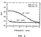
- Fig. 3 is a graph illustrating off tape and on tape power in dBm detected by a spectrum analyzer versus frequency in MHz.
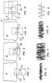
- Fig. 4 is a schematic illustration of a magnetic head with an MR element showing the MR element completely off a magnetic tape.
- Fig. 5 shows an exemplary noise signal produced by the MR element of Fig. 4.
- Fig. 6 is a schematic illustration of a magnetic head with an MR element showing the element located completely on a moving magnetic tape.
- Fig. 7 shows an exemplary noise signal produced by the MR element in Fig. 6.
- Fig. 8 is a schematic illustration of a magnetic head with an MR element showing the element located where the edge of the tape bisects the width of the MR element.
- Fig. 9 shows an exemplary noise signal produced by the MR element of Fig. 8.
- Fig. 10 is a schematic illustration of a magnetic head with an MR element showing the element centred over a desired track on the moving magnetic tape.
- Fig. 11 shows exemplary data read by the MR element in Fig. 10.
- Fig. 12 is a schematic illustration of exemplary circuitry for positioning the magnetic head so that the MR element can be located in a known position with respect to the edge of the magnetic tape.
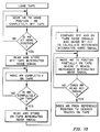
- Fig. 13 is an exemplary flow diagram for the processor of Fig. 12.
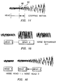
- Figs. 14, 15, and 16 are schematic illustrations of one or more noise signal configurations for determining the location of the edge of a magnetic tape according to the invention.
- a magnetic tape drive 20 which may include a magnetic tape 22, the magnetic tape 22 being driven between a pair of reels 24 and 26.
- the reel 24 may be operated by a motor 28 which is controlled by motor control 30 and the reel 26 may be operated by a motor 32 which is also controlled by the motor control 30.
- a magnetic head 40 engages and disengages the magnetic tape 22 and is capable upon engagement of writing and/or reading the tape.
- a motor 42 is connected to the head 40 for positioning the head, and the head 40 and the motor 42 are connected to a controller 44 for controlling the motor as well as processing signals to and from the magnetic head 40.
- Fig. 2 is a schematic illustration of an MR element 48 included in the head 40.
- the MR element is a thin film which is sandwiched between thin film gap layers (not shown), which in turn are sandwiched between first and second thin film shield layers (not shown).
- first and second thin film shield layers not shown.
- the MR element has an active portion 48, which is located between inactive portions 50 and 52.
- the inactive portions 50 and 52 are rendered inactive to magnetic flux incursions by the connection of leads 54 and 56 thereto.
- the leads 54 and 56 are connected to a DC source 58, which transmits a DC sense current through the active portion 48 of the MR element.
- the MR element is typically constructed of Permalloy, which is NiFe.
- the resistance of the active portion changes proportionally to the strength of the field.
- a corresponding change in voltage occurs between the leads 54 and 56.
- Voltage changes are detected by a differential amplifier 60 connected across the leads 54 and 56.
- the prior art has relied upon reading flux incursions at the edge of a tape for determining the location of the MR element with respect to the edge of the tape.
- the present invention relies upon another phenomenon of the MR element. This phenomenon is the change in resistance of the MR element due to temperature changes caused by heating of the MR element when it is in contact with a moving magnetic tape. When the MR element is completely on a moving magnetic tape, friction therebetween heats the MR element, causing an increase in resistance, which produces a noise voltage at the differential amplifier 60. When the MR element is completely off the tape, the magnitude of this noise voltage is small and is due to intrinsic characteristics of the MR element plus circuitry connected thereto.
- Fig. 3 best illustrates this phenomenon, which the invention embraces as a benefit rather than treating as a detriment.
- Fig. 3 illustrates graphs of on tape noise power (integrated noise voltage) and off tape noise power of an MR element in dBm versus frequency in MHz from 0 to 5 MHz.
- the on tape power is derived from the magnitude of the noise voltage measured across an MR element when the bearing surface of the element is entirely on a moving tape.
- the off tape power is measured when the bearing surface is entirely out of contact with tape.
- the off tape noise power is intrinsic, while the on tape noise power is due to rubbing friction of the moving magnetic tape with the MR element.
- the differential noise power is at a maximum of about 12 dBm within a frequency range of approximately 0.5 MHz to 1.0 MHz. This is referred to as "slot noise".
- Figs. 4, 6, 8 and 10 are schematic illustrations of the relative positions of the magnetic head 40 (with the MR transducer 46) and the tape 22.
- Figs. 5, 7 and 9 show noise voltage as measured by the MR element 46.
- the magnetic head 40 is located such that the MR element 46 is completely off the tape 22.
- a representative intrinsic noise signal produced by the MR element 46 is illustrated in Fig. 5.
- the magnetic head 40 has been moved to place the MR element 46 completely on the tape which will produce a much larger noise signal, as illustrated in Fig. 7.
- Fig. 8 shows the magnetic head 40 positioned with the edge 22E of the moving magnetic tape 22 bisecting the width of the MR element 46 as shown.
- Fig. 9 is one half of the differential between the off and on powers of Figs. 5 and 7. It should be understood that the MR element 46 can be placed in any location which establishes its noise power output somewhere between the off tape power level and the on tape power level shown in Figs. 5 and 7. After the position of the MR element 46 is known with respect to a reference position, as illustrated in Fig. 8, it can be indexed to any desired data or servo track 22T as illustrated in Fig. 10. This is because the distance from the edge 22E of the tape 22 to one or more tracks on the tape is known. Assuming that a write head 62 has written data and the MR element 46 is performing a read or write verify, an exemplary data output is illustrated in Fig. 11 (not to scale with respect to Figs. 5, 7 and 9).
- FIG. 12 there is shown an apparatus for positioning a head with an MR element with respect to an edge of a tape.
- the apparatus includes a voice coil 64, which is connected to the magnetic head 40 via an actuator 66.
- the voice coil 64 is capable of linearly moving the actuator 66 in response to signals from a voice coil control 65 so that the head 40 can be moved back and forth linearly across the width of the tape 22.
- the actuator may have a transverse projection 68, which is engageable with a stop 70 for establishing a home or crash stop position of the head 40 within the tape drive. This can also be the position where the MR element 46 is completely off the tape so as to make an off tape noise voltage reading.
- Fig. 12 also illustrates a preferred controller 44 for activating the voice coil control 65 in response to signals from the MR element 46.
- the off tape noise voltage reading is detected by a differential amplifier 60, which is connected across the leads of the MR element 46, as illustrated in Fig. 2.
- This off tape noise voltage is received by a bandpass filter 72, which may operate between 0.5 to 1.0 MHz.
- This provides a slot noise voltage within this bandwidth which is received by a rectifier 74.
- the output of the rectifier is integrated by an integrator 76, which sums the off track slot noise power and feeds it to a processor 78.
- the processor 78 controls the voice coil control 65, which energizes the voice coil 64.
- the voice coil 64 actuates the head 40 to a completely off tape position, as illustrated in Fig. 6.
- the differential amplifier 60 now receives an on tape noise voltage, which is processed in the same way as the off tape noise voltage to the processor 78.
- the processor 78 makes a comparison between the off tape noise voltage and the on tape noise voltage, and divides it by an integer greater than 1, such as 2, to establish a reference noise voltage for positioning the MR element 46 with respect to the edge 22E of the moving magnetic tape. If the integer is 2, the MR element 46 will be positioned midway on the edge of the tape as illustrated in Fig. 8.
- the processor 78 can then utilize known information about distances of the tracks from the edge 22E to position the MR element to a desired track 22T, as illustrated in Fig. 10.
- the processor 78 also knows the width of the MR element, the distance between MR elements if the head has multi MR elements and the location of the aforementioned off tape and on tape locations.
- An exemplary flow diagram for the operation of the processor 78 is illustrated in Fig. 13. Detailed arrangements for processing are fully described in the aforementioned patents, which are incorporated by reference herein.
- Figs. 14, 15, and 16 Other arrangements for employing the thermal noise generated by friction within an MR element are illustrated in Figs. 14, 15, and 16.
- the MR element can be gradually moved toward the edge of the tape until the noise power starts to increase at location 80, after which it can be reversed in direction from some location 82 in small increments by a stepping motor back to location 80. This will correspond to a forward edge of the MR element being aligned with the edge of the tape.
- two heads can be employed with each head carrying an MR element. The heads, which are connected together, are positioned so that head one is completely off the tape and head two is completely on the tape.
- thermal noise signals can then be subtracted and divided by an integer greater than 1 to establish a reference noise power, which can be employed to position the MR element relative to the edge of the tape according to the teachings of this invention.
- Fig. 16 is similar to Fig. 14 except the noise power measurements of the MR elements of the two heads are equalized to position the MR elements at known positions.
- the present invention can be employed for a head having a single MR element or a head having multi-MR elements.
- a single MR element can be indexed to one or more desired tracks on a magnetic tape as explained hereinabove.
- the reference position is detected there are several modes for a multi-MR element.
- One mode is for one of the MR elements to be dedicated to a reference position at the edge of the tape which places the other MR elements in position to read tracks, and another mode is for the multi-MR element head to be indexed to one or more positions on the magnetic tape.
Landscapes
- Engineering & Computer Science (AREA)
- Signal Processing (AREA)
- Magnetic Heads (AREA)
- Adjustment Of The Magnetic Head Position Track Following On Tapes (AREA)
Applications Claiming Priority (2)
| Application Number | Priority Date | Filing Date | Title |
|---|---|---|---|
| US08/231,420 US5457585A (en) | 1994-04-22 | 1994-04-22 | Tape edge detector using off tape and on tape MR noise |
| US231420 | 1994-04-22 |
Publications (1)
| Publication Number | Publication Date |
|---|---|
| EP0678858A2 true EP0678858A2 (fr) | 1995-10-25 |
Family
ID=22869180
Family Applications (1)
| Application Number | Title | Priority Date | Filing Date |
|---|---|---|---|
| EP95302613A Withdrawn EP0678858A2 (fr) | 1994-04-22 | 1995-04-19 | Détection des bords d'un support magnétique |
Country Status (4)
| Country | Link |
|---|---|
| US (1) | US5457585A (fr) |
| EP (1) | EP0678858A2 (fr) |
| JP (1) | JP2853827B2 (fr) |
| KR (1) | KR0153228B1 (fr) |
Cited By (1)
| Publication number | Priority date | Publication date | Assignee | Title |
|---|---|---|---|---|
| WO2000034951A1 (fr) * | 1998-12-10 | 2000-06-15 | Koninklijke Philips Electronics N.V. | Dispositif de commande d'une bande asservie |
Families Citing this family (7)
| Publication number | Priority date | Publication date | Assignee | Title |
|---|---|---|---|---|
| KR970705133A (ko) * | 1995-06-01 | 1997-09-06 | 제이. 지. 에이. 롤페스 | 자기 기록 장치(Magnetic recording apparatus) |
| US5739972A (en) * | 1996-01-02 | 1998-04-14 | Ibm | Method and apparatus for positioning a magnetoresistive head using thermal response to servo information on the record medium |
| WO1998041981A1 (fr) * | 1997-03-14 | 1998-09-24 | Seagate Technology, Inc. | Systeme asservi d'entrainement de disques utilisant des signaux thermiques |
| US5999360A (en) * | 1996-10-15 | 1999-12-07 | Seagate Technology, Inc. | Disc drive servo system employing thermal signals |
| US6570731B2 (en) | 2001-05-14 | 2003-05-27 | Quantum Corporation | System for detecting an edge of a moving data storage medium |
| US6771456B2 (en) | 2001-05-31 | 2004-08-03 | International Business Machines Corporation | System and method for miniaturization of read/write heads |
| JP5154741B2 (ja) * | 2005-05-26 | 2013-02-27 | テクトロニクス・インターナショナル・セールス・ゲーエムベーハー | 雑音特性表示方法 |
Family Cites Families (8)
| Publication number | Priority date | Publication date | Assignee | Title |
|---|---|---|---|---|
| US4390917A (en) * | 1979-07-24 | 1983-06-28 | Olympus Optical Co., Ltd. | Device for detecting edge of magnetic tape for recording signals |
| DE3112886A1 (de) * | 1981-03-31 | 1982-10-14 | Tandberg Data A/S, Oslo | Verfahren zum erkennen einer kante eines magnetischen mediums und vorrichtung zur druchfuehrung des verfahrens |
| US4611249A (en) * | 1985-05-03 | 1986-09-09 | Eastman Kodak Company | Flux sensitive tracking |
| US4802030A (en) * | 1986-06-25 | 1989-01-31 | Hewlett-Packard Company | Head-tape alignment apparatus with a tape edge find operation |
| JPS6396716A (ja) * | 1986-10-09 | 1988-04-27 | Sankyo Seiki Mfg Co Ltd | テ−プエツジ検出方式 |
| US4786984A (en) * | 1986-12-05 | 1988-11-22 | Minnesota Mining And Manufacturing Company | Method and apparatus for locating the edge of a magnetic tape |
| JPH0624049B2 (ja) * | 1988-10-11 | 1994-03-30 | 株式会社三協精機製作所 | テープエッジ検出方法 |
| JPH07101490B2 (ja) * | 1990-07-31 | 1995-11-01 | ティアツク株式会社 | 磁気テープの縁検知方法 |
-
1994
- 1994-04-22 US US08/231,420 patent/US5457585A/en not_active Expired - Fee Related
- 1994-12-28 KR KR1019940037707A patent/KR0153228B1/ko not_active Expired - Fee Related
-
1995
- 1995-02-28 JP JP7039798A patent/JP2853827B2/ja not_active Expired - Fee Related
- 1995-04-19 EP EP95302613A patent/EP0678858A2/fr not_active Withdrawn
Cited By (1)
| Publication number | Priority date | Publication date | Assignee | Title |
|---|---|---|---|---|
| WO2000034951A1 (fr) * | 1998-12-10 | 2000-06-15 | Koninklijke Philips Electronics N.V. | Dispositif de commande d'une bande asservie |
Also Published As
| Publication number | Publication date |
|---|---|
| JP2853827B2 (ja) | 1999-02-03 |
| US5457585A (en) | 1995-10-10 |
| KR0153228B1 (ko) | 1998-12-15 |
| KR950030043A (ko) | 1995-11-24 |
| JPH0855382A (ja) | 1996-02-27 |
Similar Documents
| Publication | Publication Date | Title |
|---|---|---|
| US7031097B1 (en) | Systems and methods for using noise measurement tracks with servopositioning signals | |
| US5901001A (en) | Detection of asperities in recording surface of storage medium | |
| US6417981B1 (en) | System and method for measuring absolute transducer-medium clearance using a thermal response of an MR transducer | |
| US4996609A (en) | Magnetic head recording multitrack servo patterns | |
| KR100264485B1 (ko) | 자기저항헤드에의한제어된연마로자기디스크상의돌출된불균일한부분을제거하는방법및장치 | |
| US6019503A (en) | Method for identifying surface conditions of a moving medium | |
| US5872672A (en) | System and method for monitoring and analyzing tape servo performance | |
| US4872071A (en) | Method and apparatus for detecting abnormal operation of moving storage apparatus | |
| US5828514A (en) | Servo error detection in a noisy environment | |
| JPH09139040A (ja) | ディスク記録再生システム及びそのヘッド浮上変動検出方法 | |
| US6563659B1 (en) | Method and apparatus for servo code based tape tension measurement | |
| US5838514A (en) | Method and apparatus for calibrating a thermal response of a magnetoresistive transducer | |
| US6265868B1 (en) | System and method for measuring total track width of a test track in magnetic media | |
| US6239936B1 (en) | Method and apparatus for calibrating a thermal response of a magnetoresistive element | |
| US20040125497A1 (en) | Devices and systems for setting thresholds for rotatable storage media | |
| US7199958B2 (en) | Servo head with varying write gap width | |
| US20080192379A1 (en) | Manufacturing method for magnetic disk drive | |
| US6611389B1 (en) | Method of determining the variation of the clearance between a magnetic transducer and a recording media during track seeking | |
| US5457585A (en) | Tape edge detector using off tape and on tape MR noise | |
| US6111406A (en) | System and method for testing a write head in a combined magnetic head using an associated read sensor in the combined head | |
| US6822814B2 (en) | Write head collision detection using MR read element in disc drives | |
| JP2005166235A (ja) | トランスデューサのヘッドの位置決め方法およびヘッド位置決めサーボシステム | |
| EP0692782B1 (fr) | Magasin amovible à disque dur et magnétoresistif, entraínement à disque et salves enfouies d'asservissement en quadrature | |
| US7184233B2 (en) | Dual source tracking servo systems and associated methods | |
| US20080291564A1 (en) | Detecting head-disk contact during off-track operations |
Legal Events
| Date | Code | Title | Description |
|---|---|---|---|
| PUAI | Public reference made under article 153(3) epc to a published international application that has entered the european phase |
Free format text: ORIGINAL CODE: 0009012 |
|
| AK | Designated contracting states |
Kind code of ref document: A2 Designated state(s): DE FR GB |
|
| STAA | Information on the status of an ep patent application or granted ep patent |
Free format text: STATUS: THE APPLICATION HAS BEEN WITHDRAWN |
|
| 18W | Application withdrawn |
Withdrawal date: 19960903 |