EP0678979A2 - Koppler für Übertragungssysteme mit mehreren Frequenzbändern - Google Patents
Koppler für Übertragungssysteme mit mehreren Frequenzbändern Download PDFInfo
- Publication number
- EP0678979A2 EP0678979A2 EP95302427A EP95302427A EP0678979A2 EP 0678979 A2 EP0678979 A2 EP 0678979A2 EP 95302427 A EP95302427 A EP 95302427A EP 95302427 A EP95302427 A EP 95302427A EP 0678979 A2 EP0678979 A2 EP 0678979A2
- Authority
- EP
- European Patent Office
- Prior art keywords
- coupler
- circuit
- impedance
- frequency range
- winding
- Prior art date
- Legal status (The legal status is an assumption and is not a legal conclusion. Google has not performed a legal analysis and makes no representation as to the accuracy of the status listed.)
- Withdrawn
Links
Images


Classifications
-
- H—ELECTRICITY
- H03—ELECTRONIC CIRCUITRY
- H03H—IMPEDANCE NETWORKS, e.g. RESONANT CIRCUITS; RESONATORS
- H03H7/00—Multiple-port networks comprising only passive electrical elements as network components
- H03H7/38—Impedance-matching networks
- H03H7/40—Automatic matching of load impedance to source impedance
-
- H—ELECTRICITY
- H03—ELECTRONIC CIRCUITRY
- H03H—IMPEDANCE NETWORKS, e.g. RESONANT CIRCUITS; RESONATORS
- H03H11/00—Networks using active elements
- H03H11/02—Multiple-port networks
- H03H11/34—Networks for connecting several sources or loads working on different frequencies or frequency bands, to a common load or source
Definitions
- the present invention relates to communication systems and, more particularly, to such systems in which information is communicated in more than one frequency band.
- the information transmitted to the receiver is coupled through more than one frequency band.
- the information coupled in one frequency band may be of a different type or from a different source than that coupled in the other band.
- Voice information may be assigned to one frequency band while data is assigned to another.
- different types of data or data originating from different sources may be transmitted through different frequency bands.
- a stream of information of one type or from one source may be cyclic assigned to a particular band.
- Couplers can be provided using passive or active components. While passive components have long been used to provide the necessary coupling function, the performance objectives of certain communication system applications exceeds the capabilities of prior art couplers which utilize passive components. Couplers implemented with active devices, on the other hand, must be powered to function, and backup power capabilities must be provided in applications where it is required that the communication system continues to function during commercial power service interruptions. Providing this power backup capability adds an expense which cannot be tolerated in certain situations. It would, therefore, be desirable if the performance capabilities of a coupler implemented with passive devices could be enhanced.
- a signal coupler pursuant to the present invention includes a transformer having a primary and a secondary winding. Each transformer winding has a pair of associated winding terminals. Each winding is also split at an intermediate winding position to form a pair of supplemental winding terminals. Circuitry is provided between each pair of supplemental winding terminals so as to provide different impedances in different frequency bands.
- a first circuit which provides a first impedance in a first frequency range, is connected across the supplemental winding terminals of one winding.
- a second circuit is connected across the supplemental winding terminals of the other transformer winding.
- This second circuit in combination with the first circuit or in combination with the transformer and the first circuit, provides a second impedance in a second frequency range.
- the first circuit provides an impedance of 600 ohms in the voiceband frequency range.
- the second circuit in combination with the first, provides an impedance of 100 ohms in a frequency range extending above 40 kHz.
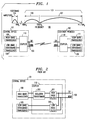
- both voice and data signals are communicated between central office 101 and customer premises 102 via communications path 103.
- path 103 is a twisted pair of wires having tip and ring leads which extend between central office 101 and customer premises 102.
- the information rate for communications from the central office to the customer premises is greater than that from the customer premises to the central office. It is for this reason that communication system 100 is referred to as being asymmetrical. It is contemplated that asymmetrical systems will be widely used as one such system, referred to as the Asymmetric Digital Subscriber Loop (ADSL) system, is proposed for offering video communications to telephone customers via the public switched telephone network (PSTN).
- ADSL Asymmetric Digital Subscriber Loop
- voice signals are bidirectionally coupled between central office 101 and customer premises 102 via the tip and ring leads of communications path 103. Such voice signals are coupled in a first frequency band 104 extending from dc to 4 kHz. Data signals are also bidirectionally coupled between central office 101 and customer premises 102 via the tip and ring leads. The data signals are coupled in a second frequency band 105 which extends from 40 kHz up to 1.7 mHz. Band 105 is subdivided into two sub-bands 106 and 107. Sub-band 106 extends from 40 kHz to 100 kHz and is allocated for the data signals coupled from customer premises 102 to central office 101.
- Sub-band 107 extends from 100 kHz to 1.7 mHz and is allocated for data signals coupled from central office 101 to customer premises 102.
- central office 101 includes high-band transceiver 108, low-band transceiver 109, and coupler 110.
- customer premises 102 includes low-band transceiver 109, coupler 110 and high-band transceiver 111.
- High-band transceivers 108 and 111 provide the bi-directional data communications, while the pair of low-band transceivers 109 provides the bi-directional voice communications. Note that the low-band transceiver located in the customer premises is identical to that located in the central office.
- the low-band transceiver may not be located in central office 101 as shown in FIG. 1. Instead, this transceiver may be disposed at a location remote from the central office. The transceiver at this remote location is then interconnected via a conventional switching network to central office 101.
- a prior art approach to implementing coupler 110 involves the use of an isolation transformer, a high-pass filter, and a low-pass filter.
- high-pass filter 201 is disposed between the tip and ring leads of communications path 103 and one winding of isolation transformer 202.
- the other winding of transformer 202 is connected to high-band transceiver 108 or 111.
- Low-pass filter 203 is also connected to the tip and ring leads of communications path 103 and serves as an interface device for low-band transceiver 109. While this arrangement may provide satisfactory results in some applications, it cannot meet the performance objectives required for communication system 100. More specifically, in communication system 100, it is necessary for the coupler to match the characteristic impedance of communication path 103 for both voice and data communications.
- the characteristic impedance of path 103 is about 600 ohms.
- the characteristic impedance of path 103 is about 100 ohms.
- the characteristic impedance provided by the coupler is the parallel combination of the high-pass filter 201 and the low-pass filter 203. That is, the characteristic impedance of the parallel combination, Z coupler, is given by 1/
- 1/
- the required 600 ohm impedance in band 104 and the required 100 ohm impedance in band 105 is a parallel combination of the impedances of high-pass filter 201 and low-pass filter 203.
- the required 600 ohm impedance is provided by making the impedance of low-pass filter 203 equal to 600 ohms and by making the impedance of high-pass filter 201 very much greater than 600 ohms.
- the required 100 ohm impedance is determined by making the impedance of high-pass filter 201 equal to 100 ohms and by making the impedance of low-pass filter 203 very much greater than 100 ohms.
- FIG. 3 shows an embodiment of a coupler 110 pursuant to the present invention
- FIG. 4 is a plot of the impedance provided by this coupler as a function of frequency.
- FIG. 4 it will be noted that in the frequency range extending up to 4 kHz, an impedance of 600 ohms is provided, and in the frequency extending from 40 kHz, an impedance of 100 ohms is provided.
- the impedance provided in the band between 4 kHz and 40 kHz varies significantly, but in the disclosed communication system, this presents no problem, as there is no information coupled within this frequency band.
- coupler 110 includes an isolation transformer 301 having a primary winding 302 and a secondary winding 303.
- Each of these windings has a pair of winding terminals.
- the turns ratio of the secondary to primary windings in transformer 301 is 1:1. This ratio is arbitrary and other ratios can be used.
- the designations of primary and secondary, relative to the windings of transformer 301 are also arbitrary.
- Reference numerals 304 and 305 designate the terminal ends of primary winding 302, while reference numerals 306 and 307 designate the terminal ends of secondary winding 303.
- the primary and secondary windings are each split at a predetermined intermediate position to form a pair of supplemental winding terminals. In the disclosed embodiment, this intermediate position is at the midpoint of both the primary and secondary windings.
- the impedance between terminals 304 and 308 is the same as that between terminals 309 and 305.
- the impedance provided between terminals 306 and 310 is the same as that provided between terminals 311 and 307.
- this selection of the intermediate position maintains longitudinal balance, i.e., the impedance from the tip lead to ground and the impedance from the ring lead to ground are the same. In a twisted pair medium, longitudinal balance is desirable, as it eliminates the formation of differential signals in the tip and ring leads caused by common-mode interference signals.
- Reference numerals 308 and 309 designate the supplemental primary winding terminals
- 310 and 311 designate the supplemental secondary winding terminals.
- the magnetic core material 320 is one continuous piece.
- the core material selected in the illustrative communication system 100 should have the capability of not saturating in the presence of loop currents in the tip and ring leads.
- Low-pass filter 312 is a four-terminal device having one pair of terminals connected to low-band transceiver 109 and another pair of terminals connected to the supplemental winding terminals 308 and 309.
- Circuit 313 is another four-terminal device having one pair of terminals, 314 and 315, connected to high-band transceiver 108 or 111, and another pair of terminals connected to supplemental secondary winding terminals 310 and 311.
- low-pass filter 312 provides a first predetermined impedance in a first frequency band while circuit 313, in combination with low-pass filter 312, provides a second impedance in a second frequency band.
- the first and second impedances are different from one another and so, too, are the first and second frequency bands.
- the low-pass filter provides a 600 ohm impedance in frequency band 104 while this filter, in combination with circuit 313, provides a 100 ohm impedance in frequency band 105.
- circuit 313 in combination with the windings of transformer 301 and low-pass filter 312, provides a high-pass filter in frequency band 105.
- Circuit 313 is a matching network which provides, in the disclosed embodiment, an impedance of 100 ohms in frequency band 105.
- This circuit includes capacitors 316, 317, 318 and resistors 319 and 320.
- Resistor 319 is connected across terminals 314 and 315 and is disposed in parallel with the series combination of resistor 320 and capacitor 318.
- Capacitor 316 is connected between terminals 310 and 314, and capacitor 317 is connected between terminals 311 and 315.
- the resistor 319 in parallel with the serial connection of resistor 320 and capacitor 318, provides the desired 100 ohm impedance.
- low-pass filter 312 can be implemented in a variety of ways.
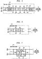
- filter 312 includes a pair of generalized impedance converters 501 and 502. Each of these converters is a four-terminal device. One pair of these terminals is connected to the supplemental secondary winding terminals, i.e., 308 and 309, while the second pair of terminals, designated as 513 and 514, is connected to a first end of the ladder network.
- One pair of the terminals of converter 502 is connected to the low-band transceiver 109 and the other pair of terminals, designated as 515 and 516, is connected to a second end of the ladder network.
- the ladder network includes inductors 503-508 and capacitors 509-512.
- Inductors 503-505 are serially connected and so, too, are inductors 506-508.
- Capacitor 509 is connected between terminals 513 and 514 of generalized impedance converter 501, while capacitor 512 is connected across terminals 515 and 516 of generalized impedance converter 502.
- Capacitors 510 and 511 are connected between the nodes formed between two serially-connected inductors.
- Circuit 312 also includes capacitor 517 which is connected between supplemental secondary winding terminals 308 and 309.
- Another implementation of filter 312 can be provided by the ladder network shown in FIG. 6. This ladder network includes two "rails" and a plurality of "rungs". The length of the rails can be varied by altering the number of inductors 601 which are serially connected to form each rail.
- each rung of the ladder interconnects two rails and is formed by a capacitor 602.
- filter 312 can be realized, as shown in FIG. 7, using an interconnection of inductors and capacitors.
- This interconnection can also be described as being a ladder network CHARACTERIZED IN THAT each rail is made of a serial connection of inductors which, in turn, is disposed in parallel with a serial connection of capacitors.
- one rail includes the serial connection of inductors 701 and 702 disposed in parallel with the serial connection of capacitors 705 and 706.
- the second rail is formed by the serial connection of inductors 703 and 704 which, in turn, is disposed in parallel with the serial connection of capacitors 710 and 711. With these two rails, there are three rungs.
- circuit 312 also includes a capacitor 712 interconnected between supplemental secondary winding terminals 308 and 309. In the arrangements shown in FIGs. 5 through 7, it is the capacitor 517 in FIG. 5, the left-most capacitor 602 in FIG. 6, and the parallel combination of capacitors 709 and 712 in FIG. 7, which primarily determine the input impedance of low-pass filter 312 in frequency band 105.
- path 103 in the disclosed embodiment is a continuous twisted pair extending between central office 101 and customer premises 102
- the present invention is also applicable in applications where one or more non-wire mediums is disposed between a twisted pair connection immediately adjacent to central office 101 and another twisted pair connection immediately adjacent to customer premises 102.
- Such non-wire mediums include optical fiber and radio links (cellular and non-cellular).
- circuit 313 in the disclosed embodiment is a particular matching network, other configurations are possible.
- the arrangement of resistor 319 in parallel with the serial combination of resistor 320 and capacitor 318 could be replaced by a single resistor.
- a serial combination of resistor and capacitor connected at one end to a parallel combination of another resistor and capacitor could be substituted for the arrangement of resistors 319, 320, and capacitor 318 shown in FIG. 3.
Landscapes
- Cable Transmission Systems, Equalization Of Radio And Reduction Of Echo (AREA)
Applications Claiming Priority (2)
| Application Number | Priority Date | Filing Date | Title |
|---|---|---|---|
| US230263 | 1994-04-20 | ||
| US08/230,263 US5528630A (en) | 1994-04-20 | 1994-04-20 | Coupler for communication systems which utilize more than one frequency band |
Publications (2)
| Publication Number | Publication Date |
|---|---|
| EP0678979A2 true EP0678979A2 (de) | 1995-10-25 |
| EP0678979A3 EP0678979A3 (de) | 1996-09-11 |
Family
ID=22864544
Family Applications (1)
| Application Number | Title | Priority Date | Filing Date |
|---|---|---|---|
| EP95302427A Withdrawn EP0678979A3 (de) | 1994-04-20 | 1995-04-12 | Koppler für Übertragungssysteme mit mehreren Frequenzbändern. |
Country Status (4)
| Country | Link |
|---|---|
| US (1) | US5528630A (de) |
| EP (1) | EP0678979A3 (de) |
| JP (1) | JPH07303020A (de) |
| TW (1) | TW280066B (de) |
Cited By (4)
| Publication number | Priority date | Publication date | Assignee | Title |
|---|---|---|---|---|
| WO1999039433A1 (en) * | 1998-01-29 | 1999-08-05 | Telefonaktiebolaget Lm Ericsson (Publ) | Active impedance converter |
| FR2798021A1 (fr) * | 1999-08-30 | 2001-03-02 | St Microelectronics Sa | Circuit hybride d'emission-reception |
| FR2798022A1 (fr) * | 1999-08-30 | 2001-03-02 | St Microelectronics Sa | Circuit hybride d'emission-reception |
| EP1089536A1 (de) * | 1999-09-29 | 2001-04-04 | Harris Corporation | Leitungsbrücke Pots/DSL Filter/Signalteiler |
Families Citing this family (33)
| Publication number | Priority date | Publication date | Assignee | Title |
|---|---|---|---|---|
| US5719856A (en) * | 1995-04-07 | 1998-02-17 | Motorola, Inc. | Transmitter/receiver interface apparatus and method for a bi-directional transmission path |
| US5757803A (en) * | 1995-11-27 | 1998-05-26 | Analog Devices, Inc. | Pots splitter assembly with improved transhybrid loss for digital subscriber loop transmission |
| US5912924A (en) * | 1996-08-15 | 1999-06-15 | Seeq Technology, Inc. | Bidirectional channels using common pins for transmit and receive paths |
| US5770996A (en) * | 1996-08-30 | 1998-06-23 | Interactive Technologies, Inc. | Transformer system for power line communications |
| US5974139A (en) * | 1997-03-07 | 1999-10-26 | Bellsouth Corporation | Line isolation device for asymmetrical digital subscriber line |
| US6449362B1 (en) | 1997-11-17 | 2002-09-10 | Bellsouth Intellectual Property Corporation | Apparatus, systems and methods for isolating ADSL signals from POTS signals |
| US6078613A (en) * | 1997-12-23 | 2000-06-20 | Paradyne Corporation | System and method for bridging multiple communication devices to a single communication connection |
| US6163579A (en) * | 1998-03-04 | 2000-12-19 | Analog Devices, Inc. | Broadband modem transformer hybird |
| US6169801B1 (en) | 1998-03-16 | 2001-01-02 | Midcom, Inc. | Digital isolation apparatus and method |
| US6385315B1 (en) * | 1998-06-05 | 2002-05-07 | Mphase Corporation | Video voice separation system |
| US6317464B1 (en) * | 1998-06-09 | 2001-11-13 | Nortel Networks Limited | Method and apparatus for separating digital data signals from analog voice signals transported over a common conductor |
| US6239672B1 (en) * | 1998-06-29 | 2001-05-29 | Cisco Technology, Inc. | Wall mount filter for a digital subscriber line (xDSL) network and methods of installation and manufacture |
| US6310894B1 (en) * | 1998-11-23 | 2001-10-30 | Verizon Laboratories Inc. | Method and apparatus for service multiplexing over telephone networks which employ bridged tap construction |
| US6222858B1 (en) | 1999-02-10 | 2001-04-24 | Verizon Laboratories Inc. | Method of inverse multiplexing for ATM |
| US6937719B2 (en) * | 1999-02-15 | 2005-08-30 | Nokia Networks Oy | Multiplexing and demultiplexing of narrowband and broadband services in a transmission connection |
| US6751315B1 (en) * | 1999-10-18 | 2004-06-15 | Silicon Labs Isolation, Inc. | High bandwidth phone line transceiver with capacitor isolation |
| US6788745B1 (en) * | 1999-11-17 | 2004-09-07 | Fujitsu Limited | Circuit and method for active termination of a transmission line |
| US7447305B2 (en) * | 2000-01-27 | 2008-11-04 | Telefonaktiebolaget Lm Ericsson (Publ) | Method and arrangement for filtering of signals |
| US6988236B2 (en) * | 2000-04-07 | 2006-01-17 | Broadcom Corporation | Method for selecting frame encoding parameters in a frame-based communications network |
| AU2002251818A1 (en) * | 2001-02-01 | 2002-08-28 | Analog Devices, Inc. | Line interface a matching impedance coupled ro a feedback path |
| US6829246B2 (en) | 2001-03-23 | 2004-12-07 | Rad Data Communications Ltd. | System and method for extending the range of xDSL services |
| US6870928B1 (en) * | 2001-05-25 | 2005-03-22 | Lsi Logic Corporation | Line interface, apparatus and method for coupling transceiver and transmission line |
| DE10151949B4 (de) * | 2001-10-22 | 2011-08-11 | Lantiq Deutschland GmbH, 85579 | Splitter-Schaltungsanordnung |
| US6999743B2 (en) * | 2001-12-07 | 2006-02-14 | Analog Devices, Inc. | Line interface with second order high pass transfer function |
| US6853724B2 (en) * | 2001-12-14 | 2005-02-08 | Adc Dsl Systems, Inc. | Cascade low-pass filter to improve xDSL band attenuation for POTS splitter |
| US6895089B2 (en) * | 2001-12-14 | 2005-05-17 | Adc Dsl Systems, Inc. | Pots splitter with line impedance matching |
| US20030198341A1 (en) * | 2002-04-23 | 2003-10-23 | Adc Dsl Systems, Inc. | Integrated POTS/MLT card |
| US7382597B2 (en) * | 2003-03-07 | 2008-06-03 | Nxp B.V. | Method and apparatus for a bondwire decoupling filter for an integrated voltage regulator and transceiver |
| US7330703B2 (en) * | 2003-06-26 | 2008-02-12 | Broadcom Corporation | Transceiver for bidirectional frequency division multiplexed transmission |
| US20050013432A1 (en) * | 2003-07-18 | 2005-01-20 | Broadcom Corporation | Hybrid circuit for bidirectional frequency division multiplexed communication |
| US8896351B2 (en) * | 2008-03-19 | 2014-11-25 | Lantiq Deutschland Gmbh | Line driver method and apparatus |
| US8929945B1 (en) * | 2013-07-18 | 2015-01-06 | Mstar Semiconductor, Inc. | Transceivers with a transformer supporting multiband operation |
| EP3048741B1 (de) * | 2013-10-25 | 2018-09-12 | Huawei Technologies Co., Ltd. | Kupferdraht-schnittstellenschaltung |
Family Cites Families (5)
| Publication number | Priority date | Publication date | Assignee | Title |
|---|---|---|---|---|
| US2797261A (en) * | 1954-04-22 | 1957-06-25 | Itt | Carrier telegraph receiver |
| BE792560A (fr) * | 1971-12-15 | 1973-03-30 | Western Electric Co | Reseaux de couplage de large bande |
| US3987375A (en) * | 1975-03-25 | 1976-10-19 | Stromberg-Carlson Corporation | Transmission bridge exhibiting reduced distortion |
| JPS61219243A (ja) * | 1985-03-26 | 1986-09-29 | Matsushita Electric Ind Co Ltd | ホ−ムバスシステム |
| US5148144A (en) * | 1991-03-28 | 1992-09-15 | Echelon Systems Corporation | Data communication network providing power and message information |
-
1994
- 1994-04-20 US US08/230,263 patent/US5528630A/en not_active Expired - Lifetime
- 1994-07-16 TW TW083106508A patent/TW280066B/zh active
-
1995
- 1995-04-12 EP EP95302427A patent/EP0678979A3/de not_active Withdrawn
- 1995-04-20 JP JP7094627A patent/JPH07303020A/ja not_active Withdrawn
Cited By (6)
| Publication number | Priority date | Publication date | Assignee | Title |
|---|---|---|---|---|
| WO1999039433A1 (en) * | 1998-01-29 | 1999-08-05 | Telefonaktiebolaget Lm Ericsson (Publ) | Active impedance converter |
| AT410384B (de) * | 1998-01-29 | 2003-04-25 | Ericsson Telefon Ab L M | Aktive impedanz-wandlerschaltungsanordnung /splitter-filter |
| FR2798021A1 (fr) * | 1999-08-30 | 2001-03-02 | St Microelectronics Sa | Circuit hybride d'emission-reception |
| FR2798022A1 (fr) * | 1999-08-30 | 2001-03-02 | St Microelectronics Sa | Circuit hybride d'emission-reception |
| EP1081874A1 (de) * | 1999-08-30 | 2001-03-07 | STMicroelectronics S.A. | Hybridschaltung für Senden und Empfang |
| EP1089536A1 (de) * | 1999-09-29 | 2001-04-04 | Harris Corporation | Leitungsbrücke Pots/DSL Filter/Signalteiler |
Also Published As
| Publication number | Publication date |
|---|---|
| JPH07303020A (ja) | 1995-11-14 |
| TW280066B (de) | 1996-07-01 |
| US5528630A (en) | 1996-06-18 |
| EP0678979A3 (de) | 1996-09-11 |
Similar Documents
| Publication | Publication Date | Title |
|---|---|---|
| US5528630A (en) | Coupler for communication systems which utilize more than one frequency band | |
| US4456985A (en) | Apparatus for coupling signals to or from a two-wire line | |
| EP0742972B1 (de) | Filtervorrichtung | |
| US6163579A (en) | Broadband modem transformer hybird | |
| US6097262A (en) | Transmission line impedance matching apparatus | |
| CA1285623C (en) | Apparatus for matching unbalanced r.f. baseband signals to balancedsignals on a twisted two-wire line | |
| US5933071A (en) | Electricity distribution and/or power transmission network and filter for telecommunication over power lines | |
| US4764922A (en) | Data terminal interface circuit to a telephone transmission line | |
| US4456986A (en) | Apparatus for coupling signals to or from a two-wire line | |
| CA1298346C (en) | Communication line transient protection | |
| US6748076B1 (en) | Method for separating narrowband and broadband services on a transmission link and a splitter element | |
| US6804349B1 (en) | Hybrid transceiver circuit | |
| US5475346A (en) | Impedance matching balum arrangement using a low pass filter | |
| US6566947B2 (en) | Combined active impedance and filter in line drivers | |
| US2333148A (en) | Inductance apparatus | |
| US7457405B2 (en) | Enhanced low pass filter | |
| RU2362269C2 (ru) | Усилитель для сигналов неэкранированной витой пары | |
| US6937719B2 (en) | Multiplexing and demultiplexing of narrowband and broadband services in a transmission connection | |
| US20030081761A1 (en) | Transformer-coupled matching impedance | |
| EP3245742B1 (de) | Systeme und verfahren für verbesserte bias-tee-designs für hochfrequenzstrom | |
| US20020186824A1 (en) | Splitterless, transformerless, voice service independent ADSL interface | |
| US2151173A (en) | Carrier and speech transmission system | |
| CA1065973A (en) | Impedance compensation of transmission lines | |
| US2272712A (en) | Electric wave transmission system | |
| CA1165914A (en) | Apparatus for coupling signals to or from a two-wire line |
Legal Events
| Date | Code | Title | Description |
|---|---|---|---|
| PUAI | Public reference made under article 153(3) epc to a published international application that has entered the european phase |
Free format text: ORIGINAL CODE: 0009012 |
|
| AK | Designated contracting states |
Kind code of ref document: A2 Designated state(s): DE FR GB |
|
| PUAL | Search report despatched |
Free format text: ORIGINAL CODE: 0009013 |
|
| AK | Designated contracting states |
Kind code of ref document: A3 Designated state(s): DE FR GB |
|
| 17P | Request for examination filed |
Effective date: 19970310 |
|
| STAA | Information on the status of an ep patent application or granted ep patent |
Free format text: STATUS: THE APPLICATION HAS BEEN WITHDRAWN |
|
| 18W | Application withdrawn |
Withdrawal date: 19980414 |