EP0679207B1 - Vorrichtung und Verfahren zur Verringerung von Emissionen erzeugt durch Versprühen von heissem flüssigen Strassenbelagsmaterial von einem sich bewegenden Fahrzeug - Google Patents
Vorrichtung und Verfahren zur Verringerung von Emissionen erzeugt durch Versprühen von heissem flüssigen Strassenbelagsmaterial von einem sich bewegenden Fahrzeug Download PDFInfo
- Publication number
- EP0679207B1 EP0679207B1 EP94906434A EP94906434A EP0679207B1 EP 0679207 B1 EP0679207 B1 EP 0679207B1 EP 94906434 A EP94906434 A EP 94906434A EP 94906434 A EP94906434 A EP 94906434A EP 0679207 B1 EP0679207 B1 EP 0679207B1
- Authority
- EP
- European Patent Office
- Prior art keywords
- vacuum hood
- emissions
- air
- spraying
- hood
- Prior art date
- Legal status (The legal status is an assumption and is not a legal conclusion. Google has not performed a legal analysis and makes no representation as to the accuracy of the status listed.)
- Expired - Lifetime
Links
- 238000005507 spraying Methods 0.000 title claims abstract description 22
- 239000007788 liquid Substances 0.000 title claims abstract description 20
- 238000000034 method Methods 0.000 title claims abstract description 12
- 239000000203 mixture Substances 0.000 title claims description 14
- 239000011387 rubberized asphalt concrete Substances 0.000 claims description 16
- 230000007246 mechanism Effects 0.000 claims description 4
- 230000001419 dependent effect Effects 0.000 claims description 2
- 229920001059 synthetic polymer Polymers 0.000 claims description 2
- 239000013618 particulate matter Substances 0.000 claims 2
- 239000003570 air Substances 0.000 description 28
- 239000000463 material Substances 0.000 description 10
- 239000010426 asphalt Substances 0.000 description 7
- 230000008569 process Effects 0.000 description 6
- 239000007921 spray Substances 0.000 description 6
- 239000002245 particle Substances 0.000 description 4
- 238000002485 combustion reaction Methods 0.000 description 3
- 239000002184 metal Substances 0.000 description 3
- 229920002209 Crumb rubber Polymers 0.000 description 2
- 230000007613 environmental effect Effects 0.000 description 2
- 239000012530 fluid Substances 0.000 description 2
- 239000012080 ambient air Substances 0.000 description 1
- 230000000712 assembly Effects 0.000 description 1
- 238000000429 assembly Methods 0.000 description 1
- 230000008901 benefit Effects 0.000 description 1
- 239000011230 binding agent Substances 0.000 description 1
- 239000000470 constituent Substances 0.000 description 1
- 239000000356 contaminant Substances 0.000 description 1
- 238000011109 contamination Methods 0.000 description 1
- 238000010586 diagram Methods 0.000 description 1
- 230000009977 dual effect Effects 0.000 description 1
- 229920001971 elastomer Polymers 0.000 description 1
- 238000009434 installation Methods 0.000 description 1
- 238000002955 isolation Methods 0.000 description 1
- 230000000704 physical effect Effects 0.000 description 1
- 238000004064 recycling Methods 0.000 description 1
- 230000007480 spreading Effects 0.000 description 1
- 230000007704 transition Effects 0.000 description 1
- 238000011144 upstream manufacturing Methods 0.000 description 1
Images

Classifications
-
- E—FIXED CONSTRUCTIONS
- E01—CONSTRUCTION OF ROADS, RAILWAYS, OR BRIDGES
- E01C—CONSTRUCTION OF, OR SURFACES FOR, ROADS, SPORTS GROUNDS, OR THE LIKE; MACHINES OR AUXILIARY TOOLS FOR CONSTRUCTION OR REPAIR
- E01C19/00—Machines, tools or auxiliary devices for preparing or distributing paving materials, for working the placed materials, or for forming, consolidating, or finishing the paving
- E01C19/12—Machines, tools or auxiliary devices for preparing or distributing paving materials, for working the placed materials, or for forming, consolidating, or finishing the paving for distributing granular or liquid materials
- E01C19/16—Machines, tools or auxiliary devices for preparing or distributing paving materials, for working the placed materials, or for forming, consolidating, or finishing the paving for distributing granular or liquid materials for applying or spreading liquid materials, e.g. bitumen slurries
- E01C19/17—Application by spraying or throwing
- E01C19/176—Spraying or throwing elements, e.g. nozzles; Arrangement thereof or supporting structures therefor, e.g. spray-bars
-
- E—FIXED CONSTRUCTIONS
- E01—CONSTRUCTION OF ROADS, RAILWAYS, OR BRIDGES
- E01C—CONSTRUCTION OF, OR SURFACES FOR, ROADS, SPORTS GROUNDS, OR THE LIKE; MACHINES OR AUXILIARY TOOLS FOR CONSTRUCTION OR REPAIR
- E01C19/00—Machines, tools or auxiliary devices for preparing or distributing paving materials, for working the placed materials, or for forming, consolidating, or finishing the paving
- E01C19/12—Machines, tools or auxiliary devices for preparing or distributing paving materials, for working the placed materials, or for forming, consolidating, or finishing the paving for distributing granular or liquid materials
- E01C19/16—Machines, tools or auxiliary devices for preparing or distributing paving materials, for working the placed materials, or for forming, consolidating, or finishing the paving for distributing granular or liquid materials for applying or spreading liquid materials, e.g. bitumen slurries
- E01C19/17—Application by spraying or throwing
Definitions
- recycled crumb rubber obtained from scrap automobile tires is mixed with paving grade liquid asphalt (usually AR 4000) at a temperature of approximately 400 degrees F ( 199 degrees C) to form a jellied composition of "asphalt-rubber" which is sprayed at 385 - 400 degrees F (189 - 199 degrees C) in quantities of approximately .55 - .65 gallons per square yard (2.5 - 2.9 liters per square meter) of pavement or used as a binder in hot mix asphalt (HMA).
- paving grade liquid asphalt usually AR 4000
- a thick cloud of visible emissions is released into the air when hot asphalt-rubber is sprayed onto a pavement surface. These emissions result from the hot liquid coming into contact with the surrounding air and then contacting the pavement itself, both of which are much cooler than the liquid.
- the emissions produced in applying heated asphalt-rubber are much greater than those produced by spraying most other materials because non-rubberized materials are typically applied in smaller quantities and/or at lower temperatures.
- a tack coat of conventional paving grade oil is applied in quantities of only approximately .05 - .10 gallons per square yard (.2 - .4 liters per square meter), and conventional prime coat oil is applied at temperatures of only approximately 150 - 180 degrees F (63 - 82 degrees C).
- a large proportion of the emissions produced by spraying heated liquid paving compositions onto a pavement surface are collected efficiently and inexpensively by the system and method of the present invention without disrupting the continuity of the spraying process or affecting the quality of the treated surface.
- a vacuum hood being mountable to the vehicle and having at least one inlet and at least one outlet; a fan or other mechanism communicating with the outlet to create a partial vacuum within the vacuum hood and draw air containing emissions through the inlet; and apparatus for receiving the air and extracting emissions therefrom.
- the vacuum hood is adjustable in a vertical direction. It may also have a primary opening adjacent its forward end and a transverse auxiliary opening in the form of a slot behind the primary opening.
- the vacuum hood has a flap extending downwardly from its underside at a location behind its inputs and transversely across the width of the vehicle.
- the vacuum hood may also have a main portion extending substantially across the vehicle and at least one side portion movable relative to the main portion between a stowed position in which it is disposed alongside the vehicle and an operating position in which it extends outwardly from the vehicle in line with the main portion.
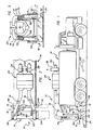
- FIGURES 1, 2 and 3 illustrate a system 10 for controlling emissions created by spraying heated liquid asphalt-rubber compositions or other suitable heated liquid paving compositions from a plurality of nozzles 12 of a distributor truck 14.
- asphalt-rubber placement is described herein as a preferred environment for use of the system 10, the system is also useful in applying other heated pavement-grade liquids which give off emissions. Examples of such liquids are hot spray applied AR 4000, AR8 or any other heated pavement grade oil, either alone or in combination with a further constituent, such as crumb rubber or a synthetic polymer.
- the emissions control system 10 has a vacuum hood 16 disposed behind the nozzles 12 to collect air containing emissions from the spraying operation and pass the air upwardly through ductwork 18 to a filter package 20.
- the vacuum hood 16 has a primary opening 22 which serves as an inlet at its forward end to collect the majority of airborne emissions and an auxiliary opening 24 located behind the primary opening for collecting secondary emissions produced as the sprayed liquid cools.
- a flexible flap 26 is disposed behind the auxiliary opening 24 to maximize the flow of air produced by the system in the area directly behind the nozzles 12.
- the air flow of the emissions control system 10 is created by a mechanism which may be a pair of fans 28 positioned downstream of the filter package 20 so that they are not exposed to contaminated air.
- the fans are driven by hydraulic motors 30 to provide a total system air flow of between 2000 and 5000, and preferably approximately 4000, cubic feet per minute (cfm).
- the filter package 20 which is seen most clearly in FIGURE 7, actually has three different "stages” capable of acting together to extract emissions from the collected air over an extended period without becoming clogged with sticky asphalt-rubber material.
- the filter package 20 is actually two filter assemblies located side-by-side, each assembly being fed by one of the fans 28.
- a first stage 32 is formed of two metal mesh filters 34 placed in series to extract relatively large contaminants (10 microns and above) and prevent them from clogging or "loading" the subsequent filter stages.
- the metal mesh filters 34 have the advantage that they can be cleaned and reused.
- a second stage 36 is a disposable paper filter rated 90 - 95% efficient for particles one micron or larger.
- a final stage 38 which is optional, is a High Efficiency Particulate Air Filter (HEPA) rated 99.5% efficient in removing particles .3 microns and larger.
- HEPA High Efficiency Particulate Air Filter
- the individual filters of the package 20 are slidable between tracks 40 for ease of removal and installation.
- a series of inclined baffles 42 are provided directly upstream of these tracks to direct contaminated air away from the tracks and thereby prevent the buildup of bituminous material along the track surfaces.
- a pressure gauge 43 (FIGURE 7) is connectable across any one or more of the filter elements through valves 45 - 55 of a gauge manifold 57. Taking the final stage 38 as an example, the pressure across it is displayed at the gauge 43 when valves 51 and 55 are open and the other valves are closed.
- a dedicated gauge can be connected directly across one or more of the filter stages to provide a constant pressure readout.
- the truck 14 is a conventional distributor truck of the type used to spray hot bituminous material, such as asphalt-rubber pavement compositions, onto pavement surfaces.
- the truck 14 has a distributor bar 44 made up of a main portion 46 and a pair of side arms 48 with distributor nozzles 12 on their underside.
- the side portions 48 are normally in the horizontal position while spreading, but can be moved upwardly to the vertical "stowed" position illustrated in full lines in FIGS. 2 and 3 when it is desired to spray a narrower pattern or when the truck is moved between jobs.
- the distributor truck 14 contains a heater for the liquid sprayed. The heater is vented through a pair of vent pipes 50.
- the vacuum hood 16 like the distributor bar 44, has a main portion 52 extending transversely across the width of the truck and a pair of side portions 54 pivotable between a vertical "stowed" position (shown in full lines in FIGURES 2 and 3) and a horizontal operating condition (shown in phantom lines at the right hand side of FIGURES 2 and 3).
- FIGURES 4, 5 and 6, The structure of the vacuum hood 16 is illustrated in more detail in FIGURES 4, 5 and 6, in which the side portions 54 are shown in the horizontal condition. As seen most clearly in FIGURES 4 and 6, the side portions 54 are attached to the main portion 52 by hinges 56 and are sealed to the main portion by gaskets 58 (FIGURE 6) to form a single air chamber.
- the vacuum hood 16 is a horizontal flat box elongated in the transverse direction and having the primary opening 22 at its forward edge or face.
- the primary opening 22 extends the full height and width of the combined vacuum hood, taking the form of an essentially open mouth cut at an angle of substantially fifty degrees from the horizontal to point generally forward and toward the pavement.
- the auxiliary opening 24 is a relatively narrow slot formed transversely across the width of the vacuum hood 16 approximately ten inches behind the forward edge of the hood.
- the vacuum hood 16 also has a pair of side doors 59 (FIGURE 4) attached to the rear edge of the main portion 52 by vertical hinges 61 to close the sides of the main portion 52 when the side portions 54 are in their stowed positions. Suitable latches (not shown) are provided to hold the side doors 59 in their closed positions. When it is desired to lower the side portions 54 in order to spray and collect emissions from a wider section of the roadway, the side doors 59 are swung outwardly and rearwardly to the position shown in FIGURE 4 before the side portions 54 are lowered.
- the side doors 59 are subsequently rotated forwardly against the rear wall of the side portions 54, in the direction indicated by the arrows 63, and held against the rear surface of the side portions 54 by latches 65.
- the vacuum hood 16 is usable in either its retracted position or its fully extended position, depending on the width of the roadway being sprayed, without loss of vacuum.
- the vacuum hood 16 has a plurality of baffles 66 extending substantially radially from the outlets 60 to provide more uniform air velocity over the width of the hood.
- the baffles extend into the side portions 54, as well as the main portion 52, to optimize air flow. Due to this configuration and the presence of the flexible flap 26, a strong flow of air into the hood is produced at all points behind the spreader bar 44, causing a large proportion of the emissions from the spraying operation to be collected.
- the dimensions of the vacuum hood 16 can vary substantially within the broad teachings of the present invention, the following information is offered by way of illustration to explain a specific preferred embodiment of the system 10.
- the main portion 52 is 8 feet (2.5 meters) wide, corresponding to the width of the distributor truck, and the side portions 54 are each approximately 3 feet (.9 meters) wide.
- the total width of the vacuum hood 16 in the fully extended condition is 14 feet (4.3 meters).
- the front-to-back dimension of the vacuum hood itself is preferably approximately 20 inches (51 centimeters), while the hood is approximately 6 inches (15 centimeters) tall.
- the primary opening 22 is preferably between 3.5 inches (9 centimeters) and 8 inches (20 centimeters) tall, and most preferably, approximately 6 inches (15 centimeters) tall.
- the front of the vacuum hood is preferably cut at a 45 degree angle so that the primary opening 22 is directed forwardly and downwardly at a location above and out of contact with the pavement being sprayed.
- the auxiliary opening 24 is preferably a slot extending the width of the vacuum hood. It can be any width less than or equal to approximately 3 inches (8 centimeters) and is preferably 2 inches (5.2 centimeters) wide.
- a total system air flow of 4000 cfm results in an air velocity at the primary opening of approximately 425 feet per minute. Under these conditions, ample air flow is provided behind the distributor bar 44 when the vacuum hood 16 is located approximately 8 to 20 inches (31 to 46 centimeters) above the pavement surface.
- the vacuum hood 16 is supported vertically by a pair of hydraulic cylinders 68 which act against support braces 70 to move the vacuum hood up or down relative to the pavement surface.
- the ductwork 18 has a flexible section 73 which permits this movement.
- the vacuum hood is preferably connected to the distributor truck 14 by links 72 (FIGURE 1) which provide fore and aft stability throughout its range of travel.
- the vacuum hood 16 is designed to support a "boot man” whose job it is to assure that liquid is sprayed uniformly from the nozzles of the spreader bar 44.
- a grating 74 is provided atop the vacuum hood 16.
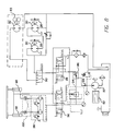
- FIGURE 8 which illustrates the hydraulic system of the present invention
- power to raise and lower the hydraulic cylinders 68 and operate the fan motors 30 derives from a single hydraulic pump 80.
- the pump 80 is powered by a motor 82 which, in the preferred embodiment, is the prime mover of the distributor truck 14.
- the hydraulic pump 80 may be a high capacity pump substituted for the pump which normally operates a combustion blower 83 of the distributor truck's engine.
- the hydraulic pump 80 provides pressurized fluid to the fan motors 30 through a check valve 84, a priority flow divider 86, a control valve 88 and a selector valve 90.
- the priority flow divider 86 ensures that the fan motors 30 and/or a combustion blower motor 92 receive priority over the hydraulic cylinders 68.
- the selector valve 90 is used to select between the combustion blower motor 92 and the fan motors 30.
- Pressurized fluid from the pump 80 is also provided to the hydraulic cylinders 68 through a second outlet of the priority flow divider 86, a pressure reducing valve 94 and a directional control valve 96. Equal flow to the two cylinders is assured by a conventional divider/combiner device 98 which feeds the cylinders 68 through a dual check module 100.
- the operator of the distributor truck first selects the desired height of the vacuum hood 16 and the grating 74 by operating the directional control valve 96 before spraying begins.
- the side portions 54 of the vacuum hood 16 are moved downwardly to their horizontal condition, if desired, as are the side portions 48 of the distributor bar 44.
- the fan motors 30 are then activated through the control valve 88 and spraying is begun.
- air containing the emissions created by the spraying operation are drawn upwardly into the vacuum hood 16, mostly through the primary opening 22 but also through the auxiliary opening 24 behind the primary opening.
- the emissions-containing air is then drawn along the ductwork 18, through the filter package 20 and out to the atmosphere as clean air.
- the system of the present invention dramatically reduces the particulate contamination created when heated liquid bituminous materials, such as heated liquid asphalt-rubber compositions, are sprayed by a distributor truck or similar vehicle.
- this function is accomplished without restricting the ability of a "boot man” to ride on the rear of the distributor truck and without impeding his access to the distributor nozzles during use.
- the spraying operation proceeds just as before, except that the emissions are collected.
Landscapes
- Engineering & Computer Science (AREA)
- Architecture (AREA)
- Civil Engineering (AREA)
- Structural Engineering (AREA)
- Road Paving Machines (AREA)
- Road Repair (AREA)
- Vehicle Cleaning, Maintenance, Repair, Refitting, And Outriggers (AREA)
Claims (27)
- System (10) zum Kontrollieren der Emissionen, die durch das Versprühen eines heißen flüssigen Straßenbelagmaterials aus mindestens einer Düse (12) von einem fahrenden Fahrzeug (14) auf einen Straßen-Oberbau entstehen, mit:einer Auffangeinrichtung (16), die so ausgelegt ist, daß sie hinter dieser mindestens einen Düse (12) und oberhalb des Oberbaus anbringbar ist, um die emissionshaltige Luft aufzufangen;einer Einrichtung (28) zum Abziehen der Luft von der Auffangeinrichtung (16) undeiner Einrichtung (20) zum Aufnehmen der Luft und zum Extrahieren der Emissionen daraus.
- System (10) nach Anspruch 1, dadurch gekennzeichnet, daßdie Auffangeinrichtung eine Vakuumhaube (16) mit mindestens einem Einlaß (22, 24) und mindestens einem Auslaß (60) aufweist unddie Abzieh-Einrichtung (28) eine Vorrichtung (28) aufweist, die mit dem mindestens einen Auslaß (60) in Verbindung steht, um ein Teilvakuum innerhalb der Vakuumhaube (16) zu erzeugen und die emissionshaltige Luft durch diesen mindestens einen Einlaß (22, 24) zu ziehen.
- System (10) nach Anspruch 2, dadurch gekennzeichnet, daß die Vorrichtung ein Gebläse (28) aufweist.
- System (10) nach Anspruch 2 oder 3, dadurch gekennzeichnet, daß die Vakuumhaube (16) in vertikaler Richtung einstellbar ist.
- System (10) nach einem der Ansprüche 2 bis 4, dadurch gekennzeichnet, daß die Vakuumhaube (16) eine Mehrzahl von Ablenkblechen (66) enthält, die sich im wesentlichen radial von dem mindestens einen Auslaß (60) ausgehend erstrecken.
- System (10) nach einem der Ansprüche 2 bis 5, dadurch gekennzeichnet, daß die Vakuumhaube (16) ein vorderes Ende und ein hinteres Ende hat und wobei der mindestens eine Einlaß eine erste Öffnung (22) aufweist, die neben dem vorderen Ende liegt.
- System (10) nach Anspruch 6, dadurch gekennzeichnet, daß die erste Öffnung (22) einen Querschlitz am vorderen Ende aufweist.
- System (10) nach Anspruch 6 oder 7, dadurch gekennzeichnet, daß der mindestens eine Einlaß ferner eine Nebenöffnung (24) aufweist, die hinter der ersten Öffnung (22) angebracht ist.
- System (10) nach Anspruch 8, dadurch gekennzeichnet, daß die Nebenöffnung (24) einen Querschlitz umfaßt und wesentlich enger als die erste Öffnung (22) ist.
- System (10) nach einem der Ansprüche 2 bis 9, dadurch gekennzeichnet, daß die Vakuumhaube (16) eine Klappe (26) aufweist, die sich neben dem mindestens einen Einlaß (22, 24) befindet.
- System (10) nach Anspruch 10, dadurch gekennzeichnet, daß die Klappe (26) biegsam ist und sich nach unten von der unteren Seite der Vakuumhaube (16) erstreckt.
- System (10) nach einem der Ansprüche 2 bis 11, dadurch gekennzeichnet, daß die Vakuumhaube (16) sich quer über das Fahrzeug (14) erstreckt.
- System (10) nach Anspruch 12, dadurch gekennzeichnet, daß die Vakuumhaube (16) aufweist:ein Hauptteil (52), das sich im wesentlichen über die Breite des Fahrzeuges (14) erstreckt undmindestens ein Seitenteil (54), das gegenüber dem Hauptteil (52) beweglich ist, zwischen einer eingefahrenen Position, in der er entlang des Fahrzeuges (14) angebracht ist und einer Betriebsposition, in der es sich nach außen vom Fahrzeug (14) als gerade Verlängerung des Hauptteils (52) erstreckt.
- System (10) nach Anspruch 13, dadurch gekennzeichnet, daß die Vakuumhaube (16) zwei Seitenteile (54) aufweist, die so angebracht sind, daß sie gegenüber dem Hauptteil (52) schwenkbar sind.
- System (10) nach Anspruch 14, dadurch gekennzeichnet, daß,jedes Seitenteil (54) mit einer entsprechenden offenen Seite des Hauptteils (52) verbunden ist unddas Hauptteil (52) eine Tür (59) umfaßt, um die offenen Seiten zu schließen, wenn die Seitenteile (54) in der eingefahrenen Position sind.
- System (10) nach einem der Ansprüche 2 bis 15, dadurch gekennzeichnet, daß die Vakuumhaube (16) sich oberhalb von und ohne Berührung mit dem Oberbau befindet, wenn sie am Fahrzeug (14) angebracht ist.
- System (10) nach einem der vorhergehenden Ansprüche, dadurch gekennzeichnet, daß die Einrichtung zum Auffangen der Luft und zum Extrahieren der Emissionen daraus einen Filter aufweist (20).
- System (10) nach Anspruch 17, dadurch gekennzeichnet, daß der Filter (20) zwischen der Vakuumhaube (16) und dem Gebläse (28) angeordnet ist.
- System (10) nach Anspruch 17 oder 18, dadurch gekennzeichnet, daß der Filter (20) eine Mehrzahl von Stufen (32, 36, 38) in Reihe aufweist, wobei jede folgende Stufe Materialteilchen extrahiert, die kleiner sind als die in der vorangegangenen Stufe extrahierten.
- System (10) nach Anspruch 19, dadurch gekennzeichnet, daß der Filter (20) mindestens eine Vorstufe (32) zum Extrahieren relativ großer Materialteilchen sowie mindestens eine nachfolgende Stufe (38) zum Extrahieren extrem feiner Emissionsteilchen aufweist.
- System (10) nach Anspruch 20, dadurch gekennzeichnet, daß die mindestens eine nachfolgende Stufe (38) einen hochwirksamen Luftfilter für Teilchen aufweist.
- System (10) nach Anspruche 20 oder 21, dadurch gekennzeichnet, daß die mindestens eine Vorstufe (32) ein metallisches Gitternetz (34) aufweist.
- System (10) nach einem der Ansprüche 20 bis 22, dadurch gekennzeichnet, daß der Filter (20) eine Zwischenstufe (36) aufweist.
- System (10) nach Anspruch 23, dadurch gekennzeichnet, daß die Zwischenstufe (36) über einen Einwegpapierfilter verfügt.
- System (10) nach einem der vorhergehenden Ansprüche, zur Verwendung beim Kontrollieren der Emissionen, die beim Versprühen heißer Asphalt-Gummi-Mischungen entstehen.
- System (10) nach einem der Ansprüche 1 bis 24, zur Verwendung beim Kontrollieren der Emissionen, die beim Versprühen von heißem, ein synthetisches Polymer enthaltenes Straßenbelagöl entstehen.
- Verfahren zum Kontrollieren der Emissionen, die durch das Versprühen eines heißen flüssigen Straßenbelagmaterials aus mindestens einer Düse (12) von einem fahrenden Fahrzeug (14) auf einen Straßen-Oberbau entstehen, mit folgenden Schritten:Zurverfügungstellung einer Vakuumhaube (16), die sich hinter der mindestens einen Düse (12) und über dem Oberbau befindet, wobei die Vakuumhaube (16) mindestens einen Einlaß (22, 24) und mindestens einen Auslaß (60) aufweist;Versprühen des heißen flüssigen Straßenbelagsmaterials aus der mindestens einen Düse (12), während das Fahrzeug (14) fährt;Erzeugen eines Teilvakuums in der Vakuumhaube (16), um emissionshaltige Luft aus dem Aufsprühvorgang durch den mindestens einen Einlaß (22, 24) abzuziehen;Extrahieren der Emissionen aus der Luft undAbgeben der Luft an die Umgebung, nachdem diese Emissionen aus ihr entfernt wurden.
Applications Claiming Priority (3)
| Application Number | Priority Date | Filing Date | Title |
|---|---|---|---|
| US08/000,748 US5297893A (en) | 1993-01-05 | 1993-01-05 | System and method for controlling emissions created by spraying liquids from moving vehicles |
| US748 | 1993-01-05 | ||
| PCT/US1993/011905 WO1994016147A1 (en) | 1993-01-05 | 1993-12-07 | System and method for controlling emissions created by spraying liquids from moving vehicles |
Publications (2)
| Publication Number | Publication Date |
|---|---|
| EP0679207A1 EP0679207A1 (de) | 1995-11-02 |
| EP0679207B1 true EP0679207B1 (de) | 1998-03-04 |
Family
ID=21692860
Family Applications (1)
| Application Number | Title | Priority Date | Filing Date |
|---|---|---|---|
| EP94906434A Expired - Lifetime EP0679207B1 (de) | 1993-01-05 | 1993-12-07 | Vorrichtung und Verfahren zur Verringerung von Emissionen erzeugt durch Versprühen von heissem flüssigen Strassenbelagsmaterial von einem sich bewegenden Fahrzeug |
Country Status (7)
| Country | Link |
|---|---|
| US (2) | US5297893A (de) |
| EP (1) | EP0679207B1 (de) |
| AT (1) | ATE163702T1 (de) |
| AU (1) | AU6014194A (de) |
| CA (1) | CA2152159C (de) |
| DE (1) | DE69317308T2 (de) |
| WO (1) | WO1994016147A1 (de) |
Families Citing this family (10)
| Publication number | Priority date | Publication date | Assignee | Title |
|---|---|---|---|---|
| US5549457A (en) * | 1995-03-27 | 1996-08-27 | Manhole Adjucting Contractors Inc. | Pavement sprayer having movable spray guard |
| US5951725A (en) * | 1995-06-07 | 1999-09-14 | National Tool And Equipment, Inc. | System for removal of noxious fumes |
| US7094001B2 (en) * | 2003-09-16 | 2006-08-22 | Granite Construction Company | Controlling emissions during asphalt paving |
| SE529187C2 (sv) * | 2005-10-10 | 2007-05-22 | Ilmeg Products Ab | System och förfarande för rening av asfaltgas |
| CA2923039C (en) | 2015-03-09 | 2023-09-12 | Heritage Research Group | Void reducing asphalt membrane composition, method and apparatus for asphalt paving applications |
| CA2923021C (en) * | 2015-03-10 | 2023-08-01 | Heritage Research Group | Apparatus and method for applying asphalt binder compositions including void reducing asphalt membrane compositions for paving applications |
| CN108867301A (zh) * | 2018-08-16 | 2018-11-23 | 王爱军 | 一种公路工程用的公路裂缝处理装置 |
| CN110917789A (zh) * | 2019-12-11 | 2020-03-27 | 江苏智动装备技术研究院有限公司 | 一种城市喷雾降尘装置 |
| CN111359356A (zh) * | 2020-03-27 | 2020-07-03 | 焦作大学 | 一种建筑施工粉尘防控装置 |
| CN118718591B (zh) * | 2024-08-05 | 2025-03-18 | 太行城乡建设集团有限公司 | 一种路面沥青冷再生摊铺用气体处理装置 |
Family Cites Families (8)
| Publication number | Priority date | Publication date | Assignee | Title |
|---|---|---|---|---|
| US3284006A (en) * | 1964-10-09 | 1966-11-08 | Horace A Cartwright | Hot spray bar for distributing roadway coating materials |
| US4069182A (en) * | 1966-10-21 | 1978-01-17 | Mcdonald Charles H | Elastomeric pavement repair composition |
| CH678342A5 (en) * | 1984-06-06 | 1991-08-30 | Peter Ag Konrad | Dust wetting road sweeping machine |
| US4557739A (en) * | 1984-08-27 | 1985-12-10 | Tennant-Company | Sweeper with precleaner and/or demister |
| US4718924A (en) * | 1986-05-30 | 1988-01-12 | Demarco Thomas M | Two compartment four stage industrial dust collector |
| US5161910A (en) * | 1990-06-29 | 1992-11-10 | Diamond Surface, Inc. | Pavement diamond grinder |
| US5108471A (en) * | 1991-05-17 | 1992-04-28 | Poborsky Gary A | Single mode wet and dry vacuum vehicle |
| US5192343A (en) * | 1991-11-01 | 1993-03-09 | Henry Harold G | High efficiency particulate air filter ventilation system |
-
1993
- 1993-01-05 US US08/000,748 patent/US5297893A/en not_active Expired - Lifetime
- 1993-12-07 EP EP94906434A patent/EP0679207B1/de not_active Expired - Lifetime
- 1993-12-07 AT AT94906434T patent/ATE163702T1/de not_active IP Right Cessation
- 1993-12-07 AU AU60141/94A patent/AU6014194A/en not_active Abandoned
- 1993-12-07 DE DE69317308T patent/DE69317308T2/de not_active Expired - Fee Related
- 1993-12-07 CA CA002152159A patent/CA2152159C/en not_active Expired - Fee Related
- 1993-12-07 WO PCT/US1993/011905 patent/WO1994016147A1/en not_active Ceased
- 1993-12-08 US US08/163,937 patent/US5342143A/en not_active Expired - Lifetime
Also Published As
| Publication number | Publication date |
|---|---|
| US5297893A (en) | 1994-03-29 |
| ATE163702T1 (de) | 1998-03-15 |
| DE69317308D1 (de) | 1998-04-09 |
| US5342143A (en) | 1994-08-30 |
| CA2152159A1 (en) | 1994-07-21 |
| DE69317308T2 (de) | 1998-10-29 |
| EP0679207A1 (de) | 1995-11-02 |
| WO1994016147A1 (en) | 1994-07-21 |
| CA2152159C (en) | 1999-03-30 |
| AU6014194A (en) | 1994-08-15 |
Similar Documents
| Publication | Publication Date | Title |
|---|---|---|
| US5470176A (en) | System and method for controlling emissions created by spraying liquids from moving vehicles | |
| EP0679207B1 (de) | Vorrichtung und Verfahren zur Verringerung von Emissionen erzeugt durch Versprühen von heissem flüssigen Strassenbelagsmaterial von einem sich bewegenden Fahrzeug | |
| US8357245B2 (en) | Stripe removal system | |
| CA1251608A (en) | Pickup truck mounted sweeper | |
| US5439313A (en) | Spray patching pavement repair system | |
| US6733086B1 (en) | Vacuum system for milling machine | |
| US5452492A (en) | Material collection | |
| US20120253612A1 (en) | Mobile pothole patching machine | |
| EP1507925A1 (de) | Absaugeinrichtung und -verfahren zur staubentsorgung bei fräsmaschinen | |
| MX2011001781A (es) | Sistema y metodo para transferencia de materiales de funcionamiento por vacio. | |
| US8012265B2 (en) | Concrete/asphalt wet washing system | |
| EP0624692A2 (de) | Arbeitsmaschine zum Beseitigen von Öl- oder Fettspuren auf Verkehrsweg-Oberflächen u.dgl. | |
| DE69928176T2 (de) | Fräsmaschine mit einer Vorrichtung zum Absaugen und Verarbeiten von Staub | |
| US5063713A (en) | Surface abrading and particle collection device | |
| US10995460B1 (en) | Cold planer dust mitigation system | |
| EP0106239B1 (de) | Gerät zum Unterhalten von asphaltierten Strassen oder Wegen | |
| EP0449542A2 (de) | Abfallsammlung | |
| DE9415472U1 (de) | Fahrbare Vorrichtung für die Reinigung und Pflege großflächiger Bereiche | |
| JP2541874B2 (ja) | 道路の舗設方法とその装置 | |
| DE202019001541U1 (de) | Flächenreinigungsfahrzeug mit einer Fräsvorrichtung zur Sanierung und Reinigung von Verkehrsflächen | |
| CN215164369U (zh) | 一种摊铺机烟尘气隔离装置 | |
| DE102019002510A1 (de) | Flächenreinigungsfahrzeug mit einer Fräsvorrichtung zur Sanierung und Reinigung von Verkehrsflächen | |
| US5645235A (en) | Dump truck with mounted comminuting device | |
| CN206050649U (zh) | 一种垃圾收集车 | |
| DE3910834C1 (de) |
Legal Events
| Date | Code | Title | Description |
|---|---|---|---|
| PUAI | Public reference made under article 153(3) epc to a published international application that has entered the european phase |
Free format text: ORIGINAL CODE: 0009012 |
|
| 17P | Request for examination filed |
Effective date: 19950802 |
|
| AK | Designated contracting states |
Kind code of ref document: A1 Designated state(s): AT BE CH DE FR IT LI NL |
|
| 17Q | First examination report despatched |
Effective date: 19960807 |
|
| GRAG | Despatch of communication of intention to grant |
Free format text: ORIGINAL CODE: EPIDOS AGRA |
|
| GRAG | Despatch of communication of intention to grant |
Free format text: ORIGINAL CODE: EPIDOS AGRA |
|
| GRAH | Despatch of communication of intention to grant a patent |
Free format text: ORIGINAL CODE: EPIDOS IGRA |
|
| GRAH | Despatch of communication of intention to grant a patent |
Free format text: ORIGINAL CODE: EPIDOS IGRA |
|
| GRAA | (expected) grant |
Free format text: ORIGINAL CODE: 0009210 |
|
| AK | Designated contracting states |
Kind code of ref document: B1 Designated state(s): AT BE CH DE FR IT LI NL |
|
| PG25 | Lapsed in a contracting state [announced via postgrant information from national office to epo] |
Ref country code: NL Free format text: LAPSE BECAUSE OF FAILURE TO SUBMIT A TRANSLATION OF THE DESCRIPTION OR TO PAY THE FEE WITHIN THE PRESCRIBED TIME-LIMIT Effective date: 19980304 Ref country code: LI Free format text: LAPSE BECAUSE OF FAILURE TO SUBMIT A TRANSLATION OF THE DESCRIPTION OR TO PAY THE FEE WITHIN THE PRESCRIBED TIME-LIMIT Effective date: 19980304 Ref country code: IT Free format text: LAPSE BECAUSE OF FAILURE TO SUBMIT A TRANSLATION OF THE DESCRIPTION OR TO PAY THE FEE WITHIN THE PRE;WARNING: LAPSES OF ITALIAN PATENTS WITH EFFECTIVE DATE BEFORE 2007 MAY HAVE OCCURRED AT ANY TIME BEFORE 2007. THE CORRECT EFFECTIVE DATE MAY BE DIFFERENT FROM THE ONE RECORDED.SCRIBED TIME-LIMIT Effective date: 19980304 Ref country code: CH Free format text: LAPSE BECAUSE OF FAILURE TO SUBMIT A TRANSLATION OF THE DESCRIPTION OR TO PAY THE FEE WITHIN THE PRESCRIBED TIME-LIMIT Effective date: 19980304 Ref country code: BE Free format text: LAPSE BECAUSE OF FAILURE TO SUBMIT A TRANSLATION OF THE DESCRIPTION OR TO PAY THE FEE WITHIN THE PRESCRIBED TIME-LIMIT Effective date: 19980304 Ref country code: AT Free format text: LAPSE BECAUSE OF FAILURE TO SUBMIT A TRANSLATION OF THE DESCRIPTION OR TO PAY THE FEE WITHIN THE PRESCRIBED TIME-LIMIT Effective date: 19980304 |
|
| REF | Corresponds to: |
Ref document number: 163702 Country of ref document: AT Date of ref document: 19980315 Kind code of ref document: T |
|
| REG | Reference to a national code |
Ref country code: CH Ref legal event code: EP |
|
| REF | Corresponds to: |
Ref document number: 69317308 Country of ref document: DE Date of ref document: 19980409 |
|
| ET | Fr: translation filed | ||
| NLV1 | Nl: lapsed or annulled due to failure to fulfill the requirements of art. 29p and 29m of the patents act | ||
| REG | Reference to a national code |
Ref country code: CH Ref legal event code: PL |
|
| PLBE | No opposition filed within time limit |
Free format text: ORIGINAL CODE: 0009261 |
|
| STAA | Information on the status of an ep patent application or granted ep patent |
Free format text: STATUS: NO OPPOSITION FILED WITHIN TIME LIMIT |
|
| 26N | No opposition filed | ||
| PGFP | Annual fee paid to national office [announced via postgrant information from national office to epo] |
Ref country code: FR Payment date: 20011120 Year of fee payment: 9 |
|
| PGFP | Annual fee paid to national office [announced via postgrant information from national office to epo] |
Ref country code: DE Payment date: 20011123 Year of fee payment: 9 |
|
| PG25 | Lapsed in a contracting state [announced via postgrant information from national office to epo] |
Ref country code: DE Free format text: LAPSE BECAUSE OF NON-PAYMENT OF DUE FEES Effective date: 20030701 |
|
| PG25 | Lapsed in a contracting state [announced via postgrant information from national office to epo] |
Ref country code: FR Free format text: LAPSE BECAUSE OF NON-PAYMENT OF DUE FEES Effective date: 20030901 |
|
| REG | Reference to a national code |
Ref country code: FR Ref legal event code: ST |