EP0679360A2 - Poignée en 'U' pour handicapés - Google Patents
Poignée en 'U' pour handicapés Download PDFInfo
- Publication number
- EP0679360A2 EP0679360A2 EP95106158A EP95106158A EP0679360A2 EP 0679360 A2 EP0679360 A2 EP 0679360A2 EP 95106158 A EP95106158 A EP 95106158A EP 95106158 A EP95106158 A EP 95106158A EP 0679360 A2 EP0679360 A2 EP 0679360A2
- Authority
- EP
- European Patent Office
- Prior art keywords
- bow handle
- holder
- handle according
- slip clutch
- wall plate
- Prior art date
- Legal status (The legal status is an assumption and is not a legal conclusion. Google has not performed a legal analysis and makes no representation as to the accuracy of the status listed.)
- Withdrawn
Links
Images
Classifications
-
- A—HUMAN NECESSITIES
- A47—FURNITURE; DOMESTIC ARTICLES OR APPLIANCES; COFFEE MILLS; SPICE MILLS; SUCTION CLEANERS IN GENERAL
- A47K—SANITARY EQUIPMENT; ACCESSORIES THEREFOR, e.g. TOILET ACCESSORIES
- A47K17/00—Other sanitary equipment not covered by the other groups of this subclass ; Holders for toilet brushes
- A47K17/02—Body supports, other than seats, for closets, e.g. handles, back-rests, foot-rests; Accessories for closets, e.g. reading tables
- A47K17/022—Wall mounted grab bars or handles, with or without support on the floor
- A47K17/024—Wall mounted grab bars or handles, with or without support on the floor pivotally mounted on the wall
Definitions
- the subject of the present innovation is a bow handle for the disabled according to the preamble of protection claim 1.
- Such a bow handle is known for example from the older DE 90 16 827 U.
- a pivoting device is described there, with which it is possible to pivot the bow handle relative to a stationary plate.
- the bow handle should be self-locking in any pivot position.
- a so-called sleeve freewheel is proposed, in which the pivoting movement takes place in one direction without any significant expenditure of force, while in the opposite direction a blocking is carried out.
- the present innovation is therefore based on the object of developing a loop handle of the type mentioned in such a way that its pivoting into any pivoting position can be carried out simply and reliably and that pivoting back can also take place without substantial effort and without significant wear and tear.
- the innovation is based on the further task of making the handicap handle as ergonomic as possible.
- the innovation is characterized by the technical teaching of claim 1.
- the handle consists essentially of two arms which are connected to one another at their front end and which are arranged offset in the vertical direction with respect to one another, the arms being received in a holder, which holder essentially around a horizontal axis is pivotally received on a stationary plate, and that the pivoting between the arms and the stationary plate takes place under the action of a spring-loaded slip clutch.
- a relatively easy to construct bow handle is proposed, which is essentially U-shaped and the two U-arms are connected to each other in their front end.
- slip clutch acts on both sides of the wall-side plate in order to ensure a favorable power transmission.
- the slip clutch is adjustable and a threaded bushing is provided for this purpose, which can be screwed more or less tightly into an associated threaded bore so as to change the pressing force on a friction disk or a plate spring.
- the screw-in depth of the threaded bushing is then determined by a clamping screw.
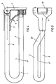
- the bow handle 1 consists essentially of two arms 2, 3, which are arranged at an angle to one another in the vertical direction one above the other and are connected to one another at their front free ends.
- the rear free ends of the arms 2, 3 are received in a holder 4, which is made of plastic or metal.
- the arms can also be arranged directly one above the other in the vertical direction in one plane.
- An upper tubular receptacle 5 for the rear end of the amre 2 is arranged in the holder 4 and the rear end of the arm 3 is received in an underlying receptacle 6.
- the lower receptacle 6 is adjustable, to make the angle of inclination of the arms 2, 3 adjustable in the direction of the horizontal.
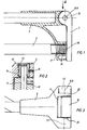
- the holder-side end of the arm 3 is designed as a threaded tube 17, into which a threaded bushing 18 can be screwed in, the rear end of which rests on a stop surface 19 on a wall plate 7.
- the angular position of the arm 3 in the direction of the horizontal is thus adjusted in accordance with the screwing depth of the threaded bushing 18 into the threaded tube 17.
- the entire holder 4 is pivotally held in the pivot axis 8 on the wall plate 7 to be fastened to a wall.
- a shaft 9 is provided which extends through the head 10 of the wall plate 7, an approximately U-shaped recess 11 being formed between the head 10 of the wall plate 7 and the associated holder 5, which is penetrated by the shaft 9.
- a threaded bore 12 is arranged in the holder 5, into which a threaded bushing 13 is screwed.
- the inside end of the threaded bushing 13 acts on a spring washer 14 or on a plate spring, which in turn is supported on the end face of the head 10 of the wall plate 7.
- a similar slip clutch is formed on the opposite side, as shown in FIG. 3.
- the two arms 2, 3 are offset from one another in the horizontal direction, and in this case a connecting arm 20 is provided which enables the upper arm 2 to be laterally offset from the lower arm 3, a through-opening 21 between the two arms is created.
Landscapes
- Health & Medical Sciences (AREA)
- Public Health (AREA)
- Epidemiology (AREA)
- General Health & Medical Sciences (AREA)
- Mechanical Operated Clutches (AREA)
- Electrophonic Musical Instruments (AREA)
- Rehabilitation Tools (AREA)
- Switches With Compound Operations (AREA)
Applications Claiming Priority (2)
| Application Number | Priority Date | Filing Date | Title |
|---|---|---|---|
| DE9407232U | 1994-04-30 | ||
| DE9407232U DE9407232U1 (de) | 1994-04-30 | 1994-04-30 | Bügelgriff für Behinderte |
Publications (2)
| Publication Number | Publication Date |
|---|---|
| EP0679360A2 true EP0679360A2 (fr) | 1995-11-02 |
| EP0679360A3 EP0679360A3 (fr) | 1996-03-20 |
Family
ID=6908089
Family Applications (1)
| Application Number | Title | Priority Date | Filing Date |
|---|---|---|---|
| EP95106158A Withdrawn EP0679360A3 (fr) | 1994-04-30 | 1995-04-25 | Poignée en 'U' pour handicapés. |
Country Status (2)
| Country | Link |
|---|---|
| EP (1) | EP0679360A3 (fr) |
| DE (1) | DE9407232U1 (fr) |
Cited By (1)
| Publication number | Priority date | Publication date | Assignee | Title |
|---|---|---|---|---|
| EP1967112A3 (fr) * | 2007-03-05 | 2014-10-29 | Erlau AG | Système de poignée |
Family Cites Families (8)
| Publication number | Priority date | Publication date | Assignee | Title |
|---|---|---|---|---|
| GB1321193A (en) * | 1971-03-03 | 1973-06-20 | Universal Oil Prod Co | Seats |
| US4196480A (en) * | 1973-10-10 | 1980-04-08 | C. D. Sparling Co. | Toilet support |
| DE2743172C2 (de) * | 1977-09-26 | 1982-12-16 | Ignaz Vogel Gmbh Und Co Kg - Fahrzeugsitze, 7500 Karlsruhe | Fahrgastsitz-Tischplatte |
| US4852940A (en) * | 1987-08-20 | 1989-08-01 | Weber Aircraft Corporation | Stowable table system |
| US4902072A (en) * | 1989-03-15 | 1990-02-20 | Tela Flynt Chancellor | Chair with pivotal arm extension |
| NL9002307A (nl) * | 1990-10-23 | 1992-05-18 | Linido Bv | Steuninrichting. |
| DE9016827U1 (de) * | 1990-12-13 | 1991-02-28 | Eisen- Und Drahtwerk Erlau Ag, 73431 Aalen | Schwenkvorrichtung |
| DE4103008C1 (fr) * | 1991-02-01 | 1992-03-19 | Blanco Gmbh & Co Kg, 7519 Oberderdingen, De |
-
1994
- 1994-04-30 DE DE9407232U patent/DE9407232U1/de not_active Expired - Lifetime
-
1995
- 1995-04-25 EP EP95106158A patent/EP0679360A3/fr not_active Withdrawn
Cited By (1)
| Publication number | Priority date | Publication date | Assignee | Title |
|---|---|---|---|---|
| EP1967112A3 (fr) * | 2007-03-05 | 2014-10-29 | Erlau AG | Système de poignée |
Also Published As
| Publication number | Publication date |
|---|---|
| EP0679360A3 (fr) | 1996-03-20 |
| DE9407232U1 (de) | 1995-06-08 |
Similar Documents
| Publication | Publication Date | Title |
|---|---|---|
| EP2991806B1 (fr) | Outil de serrage | |
| EP0948939B1 (fr) | Vis pédiculaire et dispositif de montage | |
| EP0316371A1 (fr) | Dispositif de reduction pour colonne vertebrale. | |
| DE2709272A1 (de) | Schraubklemme | |
| EP3272207B1 (fr) | Appareil de travail comprenant des boîtiers partiels reliés par une articulation pivotante | |
| DE2808667C2 (de) | Spannvorrichtung zum Festspannen von Werkstücken | |
| DE10351224A1 (de) | Klemmen-Handwerkzeug | |
| DE3022440C2 (de) | Mehrteilige Grundplatte für Möbelscharniere | |
| DE69218010T2 (de) | Klemmenbefestigung | |
| DE10006587C2 (de) | Verstellbares Scharnier | |
| DE10160729B4 (de) | Befestigungsanker mit Schraubenmutter | |
| DE102019134832B4 (de) | Knick-Drehmomentschlüssel | |
| DE1503004C3 (de) | Schraubenschlüssel | |
| DE2910508C2 (de) | Sicherheitsbindung für Ski | |
| EP0679360A2 (fr) | Poignée en 'U' pour handicapés | |
| DE202005014145U1 (de) | Gelenkband für Türen oder Fenster | |
| DE7908055U1 (de) | Fliesenschneidegeraet | |
| DE3850882T2 (de) | Verstellbare Nietzange. | |
| EP0502254B1 (fr) | Outil interceps réversible | |
| DE2300750A1 (de) | Gerueststuetze | |
| DE202004015416U1 (de) | Bodenführung für ein seitlich verschiebbares Trennelement | |
| DE9110203U1 (de) | Fixateur interne zur Reposition einer lumbalen Spondylolisthesis | |
| DE615849C (de) | Kabelmantel- und Rohrschneidevorrichtung | |
| DE8405450U1 (de) | Halterung für einen Zusatzspiegel | |
| DE2607798C3 (de) | Anzeigevorrichtung fur Meß- oder Regelgerate |
Legal Events
| Date | Code | Title | Description |
|---|---|---|---|
| PUAI | Public reference made under article 153(3) epc to a published international application that has entered the european phase |
Free format text: ORIGINAL CODE: 0009012 |
|
| AK | Designated contracting states |
Kind code of ref document: A2 Designated state(s): AT BE CH DE DK ES FR GB GR IE IT LI LU MC NL PT SE |
|
| PUAL | Search report despatched |
Free format text: ORIGINAL CODE: 0009013 |
|
| AK | Designated contracting states |
Kind code of ref document: A3 Designated state(s): AT BE CH DE DK ES FR GB GR IE IT LI LU MC NL PT SE |
|
| 17P | Request for examination filed |
Effective date: 19960702 |
|
| STAA | Information on the status of an ep patent application or granted ep patent |
Free format text: STATUS: THE APPLICATION HAS BEEN WITHDRAWN |
|
| 18W | Application withdrawn |
Withdrawal date: 19970603 |