EP0679380B1 - Vorrichtung zum Transferieren und Entnehmen von Flüssigkeiten aus Flaschen, Beuteln oder ähnlichen Behältnissen für medizinische Zwecke - Google Patents
Vorrichtung zum Transferieren und Entnehmen von Flüssigkeiten aus Flaschen, Beuteln oder ähnlichen Behältnissen für medizinische Zwecke Download PDFInfo
- Publication number
- EP0679380B1 EP0679380B1 EP19950250097 EP95250097A EP0679380B1 EP 0679380 B1 EP0679380 B1 EP 0679380B1 EP 19950250097 EP19950250097 EP 19950250097 EP 95250097 A EP95250097 A EP 95250097A EP 0679380 B1 EP0679380 B1 EP 0679380B1
- Authority
- EP
- European Patent Office
- Prior art keywords
- rotationally symmetrical
- symmetrical body
- piercing
- bodies
- housing
- Prior art date
- Legal status (The legal status is an assumption and is not a legal conclusion. Google has not performed a legal analysis and makes no representation as to the accuracy of the status listed.)
- Expired - Lifetime
Links
Images


Classifications
-
- A—HUMAN NECESSITIES
- A61—MEDICAL OR VETERINARY SCIENCE; HYGIENE
- A61J—CONTAINERS SPECIALLY ADAPTED FOR MEDICAL OR PHARMACEUTICAL PURPOSES; DEVICES OR METHODS SPECIALLY ADAPTED FOR BRINGING PHARMACEUTICAL PRODUCTS INTO PARTICULAR PHYSICAL OR ADMINISTERING FORMS; DEVICES FOR ADMINISTERING FOOD OR MEDICINES ORALLY; BABY COMFORTERS; DEVICES FOR RECEIVING SPITTLE
- A61J1/00—Containers specially adapted for medical or pharmaceutical purposes
- A61J1/14—Details; Accessories therefor
- A61J1/20—Arrangements for transferring or mixing fluids, e.g. from vial to syringe
- A61J1/2089—Containers or vials which are to be joined to each other in order to mix their contents
-
- A—HUMAN NECESSITIES
- A61—MEDICAL OR VETERINARY SCIENCE; HYGIENE
- A61J—CONTAINERS SPECIALLY ADAPTED FOR MEDICAL OR PHARMACEUTICAL PURPOSES; DEVICES OR METHODS SPECIALLY ADAPTED FOR BRINGING PHARMACEUTICAL PRODUCTS INTO PARTICULAR PHYSICAL OR ADMINISTERING FORMS; DEVICES FOR ADMINISTERING FOOD OR MEDICINES ORALLY; BABY COMFORTERS; DEVICES FOR RECEIVING SPITTLE
- A61J1/00—Containers specially adapted for medical or pharmaceutical purposes
- A61J1/14—Details; Accessories therefor
- A61J1/20—Arrangements for transferring or mixing fluids, e.g. from vial to syringe
- A61J1/2003—Accessories used in combination with means for transfer or mixing of fluids, e.g. for activating fluid flow, separating fluids, filtering fluid or venting
- A61J1/2006—Piercing means
- A61J1/201—Piercing means having one piercing end
-
- A—HUMAN NECESSITIES
- A61—MEDICAL OR VETERINARY SCIENCE; HYGIENE
- A61J—CONTAINERS SPECIALLY ADAPTED FOR MEDICAL OR PHARMACEUTICAL PURPOSES; DEVICES OR METHODS SPECIALLY ADAPTED FOR BRINGING PHARMACEUTICAL PRODUCTS INTO PARTICULAR PHYSICAL OR ADMINISTERING FORMS; DEVICES FOR ADMINISTERING FOOD OR MEDICINES ORALLY; BABY COMFORTERS; DEVICES FOR RECEIVING SPITTLE
- A61J1/00—Containers specially adapted for medical or pharmaceutical purposes
- A61J1/14—Details; Accessories therefor
- A61J1/20—Arrangements for transferring or mixing fluids, e.g. from vial to syringe
- A61J1/2003—Accessories used in combination with means for transfer or mixing of fluids, e.g. for activating fluid flow, separating fluids, filtering fluid or venting
- A61J1/2006—Piercing means
- A61J1/2013—Piercing means having two piercing ends
-
- A—HUMAN NECESSITIES
- A61—MEDICAL OR VETERINARY SCIENCE; HYGIENE
- A61J—CONTAINERS SPECIALLY ADAPTED FOR MEDICAL OR PHARMACEUTICAL PURPOSES; DEVICES OR METHODS SPECIALLY ADAPTED FOR BRINGING PHARMACEUTICAL PRODUCTS INTO PARTICULAR PHYSICAL OR ADMINISTERING FORMS; DEVICES FOR ADMINISTERING FOOD OR MEDICINES ORALLY; BABY COMFORTERS; DEVICES FOR RECEIVING SPITTLE
- A61J1/00—Containers specially adapted for medical or pharmaceutical purposes
- A61J1/14—Details; Accessories therefor
- A61J1/20—Arrangements for transferring or mixing fluids, e.g. from vial to syringe
- A61J1/2003—Accessories used in combination with means for transfer or mixing of fluids, e.g. for activating fluid flow, separating fluids, filtering fluid or venting
- A61J1/2068—Venting means
- A61J1/2072—Venting means for internal venting
-
- A—HUMAN NECESSITIES
- A61—MEDICAL OR VETERINARY SCIENCE; HYGIENE
- A61J—CONTAINERS SPECIALLY ADAPTED FOR MEDICAL OR PHARMACEUTICAL PURPOSES; DEVICES OR METHODS SPECIALLY ADAPTED FOR BRINGING PHARMACEUTICAL PRODUCTS INTO PARTICULAR PHYSICAL OR ADMINISTERING FORMS; DEVICES FOR ADMINISTERING FOOD OR MEDICINES ORALLY; BABY COMFORTERS; DEVICES FOR RECEIVING SPITTLE
- A61J1/00—Containers specially adapted for medical or pharmaceutical purposes
- A61J1/14—Details; Accessories therefor
- A61J1/20—Arrangements for transferring or mixing fluids, e.g. from vial to syringe
- A61J1/2003—Accessories used in combination with means for transfer or mixing of fluids, e.g. for activating fluid flow, separating fluids, filtering fluid or venting
- A61J1/2068—Venting means
- A61J1/2075—Venting means for external venting
-
- A—HUMAN NECESSITIES
- A61—MEDICAL OR VETERINARY SCIENCE; HYGIENE
- A61J—CONTAINERS SPECIALLY ADAPTED FOR MEDICAL OR PHARMACEUTICAL PURPOSES; DEVICES OR METHODS SPECIALLY ADAPTED FOR BRINGING PHARMACEUTICAL PRODUCTS INTO PARTICULAR PHYSICAL OR ADMINISTERING FORMS; DEVICES FOR ADMINISTERING FOOD OR MEDICINES ORALLY; BABY COMFORTERS; DEVICES FOR RECEIVING SPITTLE
- A61J1/00—Containers specially adapted for medical or pharmaceutical purposes
- A61J1/14—Details; Accessories therefor
- A61J1/20—Arrangements for transferring or mixing fluids, e.g. from vial to syringe
- A61J1/2003—Accessories used in combination with means for transfer or mixing of fluids, e.g. for activating fluid flow, separating fluids, filtering fluid or venting
- A61J1/2079—Filtering means
- A61J1/2082—Filtering means for gas filtration
-
- A—HUMAN NECESSITIES
- A61—MEDICAL OR VETERINARY SCIENCE; HYGIENE
- A61J—CONTAINERS SPECIALLY ADAPTED FOR MEDICAL OR PHARMACEUTICAL PURPOSES; DEVICES OR METHODS SPECIALLY ADAPTED FOR BRINGING PHARMACEUTICAL PRODUCTS INTO PARTICULAR PHYSICAL OR ADMINISTERING FORMS; DEVICES FOR ADMINISTERING FOOD OR MEDICINES ORALLY; BABY COMFORTERS; DEVICES FOR RECEIVING SPITTLE
- A61J1/00—Containers specially adapted for medical or pharmaceutical purposes
- A61J1/14—Details; Accessories therefor
- A61J1/20—Arrangements for transferring or mixing fluids, e.g. from vial to syringe
- A61J1/2003—Accessories used in combination with means for transfer or mixing of fluids, e.g. for activating fluid flow, separating fluids, filtering fluid or venting
- A61J1/2079—Filtering means
- A61J1/2086—Filtering means for fluid filtration
-
- Y—GENERAL TAGGING OF NEW TECHNOLOGICAL DEVELOPMENTS; GENERAL TAGGING OF CROSS-SECTIONAL TECHNOLOGIES SPANNING OVER SEVERAL SECTIONS OF THE IPC; TECHNICAL SUBJECTS COVERED BY FORMER USPC CROSS-REFERENCE ART COLLECTIONS [XRACs] AND DIGESTS
- Y10—TECHNICAL SUBJECTS COVERED BY FORMER USPC
- Y10T—TECHNICAL SUBJECTS COVERED BY FORMER US CLASSIFICATION
- Y10T137/00—Fluid handling
- Y10T137/794—With means for separating solid material from the fluid
- Y10T137/8122—Planar strainer normal to flow path
-
- Y—GENERAL TAGGING OF NEW TECHNOLOGICAL DEVELOPMENTS; GENERAL TAGGING OF CROSS-SECTIONAL TECHNOLOGIES SPANNING OVER SEVERAL SECTIONS OF THE IPC; TECHNICAL SUBJECTS COVERED BY FORMER USPC CROSS-REFERENCE ART COLLECTIONS [XRACs] AND DIGESTS
- Y10—TECHNICAL SUBJECTS COVERED BY FORMER USPC
- Y10T—TECHNICAL SUBJECTS COVERED BY FORMER US CLASSIFICATION
- Y10T137/00—Fluid handling
- Y10T137/8593—Systems
- Y10T137/86292—System with plural openings, one a gas vent or access opening
- Y10T137/86324—Tank with gas vent and inlet or outlet
- Y10T137/86332—Vent and inlet or outlet in unitary mounting
Definitions
- the invention relates to a device for transferring and removing Liquids from bottles, bags or similar containers for medical purposes Purposes with diagonally opposite axes practically on one axis Spikes, each with two flow channels. Such Devices are also referred to as transfer and removal spikes.
- DE 3627231 A1 describes a transfer device for mixing medications located in different containers, consisting of two piercing mandrels which are directed in the opposite direction and are connected to one another, each of which is provided with a continuous liquid channel and a ventilation channel, and which is characterized in that the Transfer device consists of two components that can be coupled to one another, each component being provided with a piercing mandrel and the liquid channels being connected to one another in the coupled state, while each ventilation mandrel ends in a ventilation opening.
- This device is not only complicated to manufacture and handle, but also has the disadvantage that two air filters are required. In addition, there is no possibility of keeping the remaining liquid to be used closed in the storage vessel.
- DE 3820204 A1 describes a device for the filtered supply or removal of liquid into or from a container, in particular a bottle, in which separate chambers for the liquid channel and the air channel are arranged in a carrier plate, each containing filter elements.
- the device has the disadvantage of complicated manufacture and handling.
- This device is therefore only suitable as a removal and not as a transfer spike.
- DE 4122221 A1 describes a transfer and removal spike in which a carrier plate is provided with piercing mandrels arranged diametrically to one another, through which two flow channels are guided, with which a shut-off element cooperates, which in an open position releases the flow through the flow channel and blocks the flow through the flow channel in a blocking position, wherein in the blocking position a liquid removal channel comes into flow connection with a section of the flow channel open to an injection syringe and the liquid removal channel opens into a connecting piece.
- This device is not only complicated to manufacture, but also in terms of operation and functional reliability. Furthermore, massive tightness problems between the carrier plate and the shut-off element are to be expected during manufacture and handling. Here too, the bottle can only be sealed with the residual liquid at great expense.
- DE 4010202 A1 describes a removal spike which consists of a carrier plate and there is a spike that forms a structural unit with a connecting piece and a filter element is welded to the carrier plate in the area of the inlet opening. With this device can only be removed, but not transferred.
- DE 41 22 476 A1 describes a device for transferring two or two several sterile liquids in a closed system. This will be two Double cannulas inserted into each other and connected with a guide collar. This The disadvantage of the device is that it is only suitable for transferring and on the Guide collar sealing problems occur regardless of which direction the liquid exchange takes place.
- EP 0 426 403 A1 describes a device for transferring and Extract liquids known in the two spikes one straight Have flow channel during gas exchange through two separate air filters should be done.
- the main disadvantage of this device is that it Air filters, if they are to serve their purpose, such a high flow resistance have that the transfer either does not start at all or only very slowly and is therefore time consuming.
- the object of the present invention is to avoid the disadvantages of the prior art the technology, a device for transferring and removing liquids To create bottles, bags or similar containers that are not just quick Mixing two media, but also the storage of residual quantities and the targeted removal of partial quantities. It is intended with a view to environmentally friendly production and disposal from as few and small components as possible exist with light weight.
- the object is achieved in that the device for transferring and Removing liquids from bottles, bags or similar containers for medical purposes with practically on one axis, diametrically opposite spikes, each with two flow channels are, the two plungers in a rotationally symmetrical body pass, which can be plugged into each other centrally, such that the one flow channel practically ensures a straight flow in the axial direction and after the principle of the modular system for removing the solution to be used, after the rotationally symmetrical body with the larger diameter from rotationally symmetrical body with the smaller diameter is separated via lower end of the rotationally symmetrical body with the smaller diameter provided threaded cams a housing consisting of an upper part and a Lower part arranged and the housing compared to the smaller one rotationally symmetrical body is sealed by means of a sealing surface, the other flow channel, which is in the area of the tip of the Spike has a capillary-like constriction between the two Spikes in the form of annular recesses within the rotationally symmetrical body is formed, the
- the rotationally symmetrical bodies are U-shaped.
- the U-shaped design is designed such that a larger diameter cylindrical guide and seal is arranged while in the area of the smaller Diameter inside a conical guide and seal is arranged. Furthermore, it is advantageous to separate the two rotationally symmetrical bodies in the area of the smaller diameter cams in connection with radial ones inclined planes segments with a rotation range of preferably 90 ° arranged are.
- two or more snap hooks distributed symmetrically on the circumference are arranged in the region of the larger diameter of the rotationally symmetrical body.
- the solution according to the invention has a number of decisive advantages. It is thus possible to dissolve a mostly toxic dry substance with a liquid in a closed system without aerosols escaping into the environment and thus without any risk for the user or the patient. Aeration of the containers during the liquid transfer is possible in a simple manner. After mixing, the solution can be drawn off by means of a syringe or an infusion line, optionally with an integrated drip chamber, after the smaller body has been separated from the larger, rotationally symmetrical body.
- a particular advantage is that the two containers can be separated with a single movement and the container with the usable solution is thus available separately.
- the device according to the invention is simple and inexpensive to manufacture. It has a small volume and thus generates little waste. It is also easy to handle, which is a great advantage in clinical operations.
- the invention also provides a transfer set and a simple spike for pulling off a solution from a container at the same time secure closure of the container and thus possible for safe storage of unnecessary amounts of solution possible. By rotating one of the two rotationally symmetrical bodies, the two containers can be separated quickly and easily. This simple and safe handling is made possible by the anti-twist protection of the spikes in the rubber-elastic plugs of the containers.
- the invention will be explained in more detail using an exemplary embodiment and the drawing.
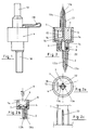
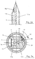
- FIG. 1 the overall view of the device according to the invention is shown.
- the essential features of the invention become clear from the sectional illustration according to FIGS. 2 to 5a.
- the two rotationally symmetrical bodies 3 and 4 which form a physical unit with the piercing mandrels 1 and 2, each adjoin two diametrically opposite piercing mandrels 1 and 2, which are generally rotationally symmetrical. Both rotationally symmetrical bodies 3 and 4 can be plugged into one another centrally.
- the rotationally symmetrical body 4 engages over the rotationally symmetrical body 3. Both are U-shaped and are provided with an annular guide and seal 5 on the largest diameter. A conical guide and seal 6 are also provided at the opposite end of the two rotationally symmetrical bodies 3 and 4. With this construction, the two rotationally symmetrical bodies 3 and 4 are centered and sealed from one another. In order to be able to loosen the two rotationally symmetrical bodies 3 and 4 again, two to three threaded cams 7 are advantageously arranged on the circumference at the lower end of the smaller rotationally symmetrical body 3, which preferably rotate by 90 ° when the two rotationally symmetrical bodies 3 and 4 are rotated sloping planes 8 slide and thus generate a rotary stroke movement to separate the connection.
- the rotatability is indicated by the arrow 9 in FIG. 2b.
- Two flow channels 12a and 13a or 12b and 13b are respectively arranged in the piercing mandrels 1 and 2.
- the arrangement of the flow channels 12a and 12b is such that they practically form an axial passage in the device according to the invention, so that, for. B. can get a liquid medium without additional flow resistance from the bottle 10 into the bottle 11.
- bottles 10; 11 instead of the bottles 10; 11, other containers or syringes or infusion lines known for medical purposes can also be used.
- the flow channels 13a and 13b are connected via an annular gap-shaped recess 14 formed between the rotationally symmetrical bodies 3 and 4
- a cutout 15 for example a bore, is arranged at the end of the flow channel 13a perpendicular to the longitudinal axis, with the interposition of an air filter 16 known per se the recess 14 is connected.
- An additional or alternative non-positive connection of the rotationally symmetrical bodies 3 and 4 is possible by means of snap hooks 17, which are arranged on the circumference of the larger rotationally symmetrical body 4 and overlap the circular surface of the rotationally symmetrical body 3 (cf. FIG. 3).
- the protective caps 18 and 19 are provided with protective caps 18 and 19. While the protective cap 18 is discarded, the protective cap 19 is connected to the device according to the invention via a flexible connecting element 20. After separating the device according to the invention, the remaining solution can be stored in the bottle 11 with the protective cap 19 which is pushed over the threaded cams 7. Part of the solution can thus be removed at any time via a syringe 21.
- these can expediently be oval or in another non-rotationally symmetrical shape or be provided with ribs 22 which are distributed along the circumference and extend in the longitudinal direction.
- FIG. 1 Another advantageous embodiment of the device according to the invention which corresponds to the modular principle consists in the following. If after transferring the solvent from the bottle 10 into the bottle 11, the bottle 10 together with the larger rotationally symmetrical body 4 of is separated from the smaller rotationally symmetrical body 3, a filter housing is attached to the smaller rotationally symmetrical body 3 via the threaded cams 7 and a thread 26 located at the base.
- the filter housing consists of an upper part 24 and a lower part 25 as well as a filter 23, which is known per se and arranged transversely to the flow direction.
- the sealing surface 28 is produced by means of a conical extension which engages in the end of the smaller rotationally symmetrical body 3.
- a syringe 21 can be attached via a threaded cam 27, which corresponds to the cam 7, and the content of the bottle 11 can be filtered out (see FIG. 5).
- the modular principle which the invention follows in the design of its individual parts, enables a pure removal spike for the filtered removal of liquids from the smaller, rotationally symmetrical body 3 by direct attachment of the filter 23 in connection with the lower part 25 of the filter housing, for example by welding or to produce solutions for medical purposes (see FIG. 5a). It has been shown that the liquid transport from bottle 10 to bottle 11 is generally too slow when used as a transfer spike (see FIGS. 2 and 6a).
- the reason for this is that the air exchange from the bottle 11 to the bottle 10 via the air filter 16 has too high a resistance at the relatively small pressure difference. Since the rotationally symmetrical bodies 3 and 4, due to the areal seals 5 and 6, do not allow any air exchange of the interior with the surroundings, the air exchange can expediently also take place in a different way than via the air filter 16 (see FIG. 2e).
- the air from the bottle 11 not only enters the bottle 10 via the cutout 14, the air filter 16, the cutout 15 and the flow channel 13a, but can also travel directly from the cutout 14 via the cutout 29, the flow channel 30 to the cutout 15 and continue via flow channel 13a to bottle 10.
- the rotationally symmetrical bodies 3 and 4 are separated from one another by a rotating movement over the inclined planes 8.
- the cam 31 presses the cover 32 shut and the plug 33 closes the flow channel 30 in an airtight manner.
- the rotary movement should cover an angle of preferably 30 ° to 45 °.
- gas exchange can then only take place via the air filter 16.
- another pluggable closure of the flow channel 30 is also possible, which can also be located at another location on the rotationally symmetrical body 3.
- the flow channel 30 can be closed via a check valve or another suitable measure.
- a constriction 13a1 of one to ten millimeters in length and a diameter of preferably 0.2 to 0.6 millimeters has proven to be particularly advantageous.
Landscapes
- Health & Medical Sciences (AREA)
- Pharmacology & Pharmacy (AREA)
- Life Sciences & Earth Sciences (AREA)
- Animal Behavior & Ethology (AREA)
- General Health & Medical Sciences (AREA)
- Public Health (AREA)
- Veterinary Medicine (AREA)
- Medical Preparation Storing Or Oral Administration Devices (AREA)
- Loading And Unloading Of Fuel Tanks Or Ships (AREA)
Description
So wird in der DE 3627231 A1 ein Überleitungsgerät zum Mischen von in unterschiedlichen Behältern befindlichen Medikamenten beschrieben, bestehend aus zwei in entgegengesetzter Richtung gerichteten und miteinander verbundenen Einstechdornen, deren jeder mit einem durchgehenden Flüssigkeitskanal und einem Belüftungskanal versehen ist und das dadurch gekennzeichnet ist, daß das Überleitungsgerät aus zwei miteinander kuppelbaren Bauteilen besteht, wobei jedes Bauteil mit einem Einstechdorn versehen ist und die Flüssigkeitskanäle im gekuppelten Zustand miteinander verbunden sind, während jeder Belüftungsdorn in einer Belüftungsöffnung endet. Dieses Gerät ist nicht nur kompliziert in Herstellung und Handhabung sondern hat auch den Nachteil, daß zwei Luftfilter erforderlich sind. Außerdem besteht keine Möglichkeit, die zu verwendende, restliche Flüssigkeit in dem Vorratsgefäß geschlossen aufzubewahren.
In der DE 4122221 A1 ist ein Transfer- und Entnahme-Spike beschrieben, bei dem eine Trägerplatte mit diametral zu einander angeordneten Einstechdornen versehen ist, durch die zwei Strömungskanäle geführt sind mit denen ein Absperrelement zusammenwirkt, das in einer Öffnungsstellung den Durchfluß durch den Strömungskanal freigibt und in einer Sperrstellung den Durchfluß durch den Strömungskanal sperrt, wobei in der Sperrstellung ein Flüssigkeitsentnahmekanal in Strömungsverbindung mit einem zu einer Einstechspritze offenen Abschnitt des Strömungskanals gelangt und der Flüssigkeitsentnahmekanal in einem Anschlußstutzen mündet.
Dieses Gerät ist nicht nur in der Fertigung kompliziert, sondern auch in der Be-dienung und der Funktionssicherheit. Weiterhin sind bei der Herstellung und Handhabung massive Dichtigkeitsprobleme zwischen der Trägerplatte und dem Absperrelement zu erwarten. Auch hier ist ein Verschluß der Flasche mit der Restflüssigkeit nur mit hohem Aufwand möglich.
Zur Vermeidung des Verdrehens bei eingestochenen Einstechdornen in einem Behältnis, ist es vorteilhaft, an der Oberfläche der Einstechdorne in axialer Richtung auf den Umfang verteilte Rippen oder Lamellen anzuordnen oder den Einstechdornen einen anderen als einen kreisförmigen Querschnitt zu geben.
So ist es möglich, eine meist toxische Trockensubstanz mit einer Flüssigkeit in einem geschlossenen System ohne Austritt von Aerosolen in die Umgebung und damit ohne jede Gefahr für den Anwender bzw. für den Patienten aufzulösen.
Eine Belüftung der Behältnisse während des Flüssigkeitsübertritts ist in einfacher Weise möglich. Nach dem Mischen ist das Abziehen der Lösung mittels einer Spritze oder einer Infusionsleitung, gegebenenfalls mit integrierter Tropfkammer, ohne Schwierigkeiten gewährleistet, nachdem der kleinere von dem größeren rotationssymmetrischen Körper getrennt ist.
Die erfindungsgemäße Vorrichtung ist einfach und kostengünstig herstellbar. Sie hat ein geringes Volumen und erzeugt damit wenig Müll. Außerdem ist sie leicht handhabbar, was im klinischen Betrieb von großem Vorteil ist. Durch die baukastenartige Konstruktion ist mit der Erfindung zugleich ein Transferset und ein einfacher Spike zum Abziehen einer Lösung aus einem Behältnis mit gleichzeitig
sicherem Verschluß des Behältnisses und damit zur sicheren Aufbewahrung nicht benötigter Lösungsmengen möglich.
Durch das Verdrehen eines der beiden rotationssymetrischen Körper ist ein schnel-les und einfaches Trennen der beiden Behältnisse möglich.
Ermöglicht wird diese einfache und sichere Handhabung durch die Verdrehsicherung der Einstechdorne in den gummielastischen Stöpseln der Behältnisse.
Anhand eines Ausführungsbeispieles und der Zeichnung soll die Erfindung näher erläutert werden.
- Fig. 1 :
- eine Gesamtansicht der erfindungsgemäßen Vorrichtung,
- Fig. 2 :
- einen Axialschnitt durch die erfindungsgemäße Vorrichtung,
- Fig. 2a :
- eine Draufsicht entsprechend Fig. 2,
- Fig. 2b :
- eine Schnittdarstellung des Trennmechanismus,
- Fig. 2c :
- eine Ansicht der Rippen auf den Einstechdornen zur Verdrehungssicherung,
- Fig. 2d :
- eine Verengung des Strömungskanals im Einstechdorn,
- Fig. 2e :
- eine Variante zur Beschleunigung des Flüssigkeitsaustausches beim Transferieren,
- Fig. 3 :
- eine Schnittdarstellung der Schnapphaken,
- Fig. 4 :
- den Sitz der Schutzkappe in zwei Stellungen,
- Fig. 5 :
- einen Axialschnitt einer Variante mit eingebautem zweiteiligen Filtergehäuse und Schutzkappe,
- Fig. 5a :
- eine Variante der Anbringung des Filtergehäuseunterteils an dem kleineren rotationssymmetrischen Körper,
- Fig. 6a :
- eine Gesamtansicht mit den beiden Behältern, die die Ausgangsstoffe enthalten,
- Fig. 6b :
- eine Ansicht mit angesetzter Spritze zum Abziehen der Lösung, ohne Filtration,
- Fig. 6c :
- eine verschlossene und für die Aufbewahrung vorgesehene Flasche,
Durch diese Konstruktion werden die beiden rotationssymmetrischen Körper 3 und 4 zueinander zentriert und abgedichtet. Um die beiden rotationssymmetrischen Körper 3 und 4 wieder lösen zu können, sind am unteren Ende des kleineren rotationssymmetrischen Körpers 3 vorteilhafterweise zwei bis drei Gewindenocken 7 am Umfang verteilt angeordnet, die bei Verdrehung der beiden rotations-symmetrischen Körper 3 und 4 um vorzugsweise 90° über schiefe Ebenen 8 gleiten und somit eine Dreh-Hubbewegung zur Trennung der Verbindung erzeugen. Die Drehbarkeit ist in Fig. 2b durch den Pfeil 9 gekennzeichnet. In den Einstechdornen 1 und 2 sind jeweils zwei Strömungskanäle 12a und 13a bzw. 12b und 13b angeordnet. Die Anordnung der Strömungskanäle 12a und 12b erfolgt so, daß sie praktisch einen axialen Durchgang in der erfindungsgemäßen Vorrichtung bilden, so daß z. B. ein flüssiges Medium ohne zusätzliche Strömungswiderstände von der Flasche 10 in die Flasche 11 gelangen kann. Anstelle der Flaschen 10; 11 sind auch andere für medizinische Zwecke bekannte Behältnisse oder Spritzen bzw. Infusionsleitungen verwendbar. Die Verbindung der Strömungskanäle 13a und 13b erfolgt über eine zwischen den rotationssymmetrischen Körpern 3 und 4 gebildete ringspaltförmige Aussparung 14
Um die Möglichkeit der Luft- bzw. Gasfilterung beim Austausch der Medien in den Flaschen 10 und 11 vorzusehen, ist am Ende des Strömungskanals 13a senkrecht zur Längsachse eine Aussparung 15, z.B. eine Bohrung angeordnet, die unter Zwischenschaltung eines an sich bekannten Luftfilters 16, mit der Aussparung 14 in Verbindung steht.
Eine zusätzliche oder alternative kraftschlüssige Verbindung der rotationssymmetrischen Körper 3 und 4 ist mittels Schnapphaken 17 möglich, die am Umfang des größeren rotationssymmetrischen Körpers 4 angeordnet sind und auf die kreisförmige Oberfläche des rotationssymmetrischen Körpers 3 übergreifen (vgl. Fig. 3). Zum Schutz der Einstechdorne vor dem Gebrauch der erfindungsgemäßen Vorrichtung sind diese mit Schutzkappen 18 und 19 versehen. Während die Schutzkappe 18 verworfen wird, ist die Schutzkappe 19 mit der erfindungs-gemäßen Vorrichtung über ein flexibles Verbindungselement 20 verbunden. Nach dem Trennen der erfindungsgemäßen Vorrichtung, kann mit der Schutzkappe 19, die über die Gewindenocken 7 geschoben wird, die restliche Lösung in der Flasche 11 aufbewahrt werden. Über eine Spritze 21 kann so jederzeit ein Teil der Lösung entnommen werden. Zur Sicherung der Einstechdorne 1 und 2 gegen Verdrehen in den gummiartigen Verschlüssen der Flaschen 10 und 11, können diese zweckmäßigerweise oval oder in anderer nicht rotationssymmetrischer Form gestaltet oder mit am Umfang verteilten, in Längsrichtung verlaufenden Rippen 22 versehen sein.
Eine weitere vorteilhafte und dem Baukastenprinzip entsprechende Aus-führungsform der erfindungsgemäßen Vorrichtung besteht in folgendem. Wenn nach dem Transferieren des Lösungsmittels aus der Flasche 10 in die Flasche 11 die Flasche 10 gemeinsam mit dem größeren rotationssymmetrischen Körper 4 von
dem kleinerem rotationssymmetrischen Körper 3 abgetrennt ist, wird über den am Ansatz befindlichen Gewindenocken 7 und ein Gewinde 26 ein Filtergehäuse an den kleineren rotationssymmetrischen Körper 3 angesetzt. Das Filtergehäuse besteht aus einem Oberteil 24 und einem Unterteil 25 sowie aus einem quer zur Strömungsrichtung angeordneten, an sich bekannten Filter 23. Über einen konischen Ansatz, der in das Ende des kleineren rotationssymetrischen Körpers 3 eingreift, wird die Dichtfläche 28 hergestellt. Über einen Gewindenocken 27, der dem Nocken 7 entspricht, kann eine Spritze 21 angesetzt und der Inhalt der Flasche 11 gefiltert entnommen werden (vergl. Fig. 5).
Weiterhin ermöglicht das Baukastenprinzip, dem die Erfindung in der Gestaltung ihrer Einzelteile folgt, aus dem kleineren rotationssymmetrischen Körper 3 durch unmittelbaren Ansatz des Filters 23 in Verbindung mit dem Unterteil 25 des Filtergehäuses, z.B. durch verschweißen, einen reinen Entnahme-Spike zur gefilterten Entnahme von Flüssigkeiten bzw. Lösungen für medizinische Zwecke herzustellen (vergl. Fig. 5a).
Es hat sich gezeigt, daß der Flüssigkeitstransport von der Flasche 10 zur Flasche 11 bei der Verwendung als Transfer-Spike (vergl. Fig. 2 und Fig. 6a) im allgemeinen zu langsam erfolgt. Der Grund dafür ist, daß der Luftaustausch von der Flasche 11 zur Flasche 10 über das Luftfilter 16 bei der relativ geringen Druckdifferenz einen zu hohen Widerstand hat.
Da die rotationssymmetrischen Körper 3 und 4 durch die flächenhaften Dichtungen 5 und 6 keinen Luftaustausch des Innenraumes mit der Umgebung zulassen, kann der Luftaustausch zweckmäßigerweise auch auf einem anderen Weg als über das Luftfilter 16 erfolgen (vergl. Fig. 2e). Die Luft aus der Flasche 11 gelangt nicht nur über die Aussparung 14, den Luftfilter 16, die Aussparung 15 und den Strömungskanal 13a in die Flasche 10, sondern kann auch den direkten Weg von der Aussparung 14 über die Aussparung 29, den Strömungskanal 30 zur Aussparung 15 und weiter über den Strömungskanal 13a zur Flasche 10 nehmen.
Nach Beendigung des Flüssigkeitstransfers werden die rotationssymmetrischen Körper 3 und 4 durch eine drehende Bewegung über die schiefen Ebenen 8 von einander getrennt. Dabei drückt der Nocken 31 den Deckel 32 zu und der Stöpsel 33 verschließt den Strömungskanal 30 luftdicht. Dabei sollte die Drehbewegung einen Winkel von vorzugsweise 30° bis 45° überstreichen.
Nach erfolgter Trennung der rotationssymmetrischen Körper 3 und 4 voneinander (vergl. Fig. 6c) kann dann ein Gasaustausch nur noch über das Luftfilter 16 erfolgen.
An Stelle des Deckels 32 mit Stöpsel 33 ist auch ein anderer einsteckbarer Verschluß des Strömungskanals 30, der sich auch an einer anderen Stelle des rotationssymmetrischen Körpers 3 befinden kann, möglich. Ebenso kann der Verschluß des Strömungskanals 30 über ein Rückschlagventil oder eine andere geeignete Maßnahme erfolgen.
Weiterhin hat es sich als zweckmäßig erwiesen, den Strömungskanal 13a an der Spitze des Einstechdorns 1 kapillarähnlich zu verengen. Dadurch wird eine gerichtete Strömung erzielt und Flüssigkeitseintritt verhindert. Als besonders vorteilhaft hat sich eine Verengung 13a1 von ein bis zehn Millimeter Länge und einen Durchmesser von vorzugsweise 0,2 bis 0,6 Millimeter erwiesen.
- 1
- Einstechdorn
- 2
- Einstechdorn
- 3
- rotaionssymmetrischer Körper
- 4
- rotationssymmetrischer Körper
- 5
- Dichtung
- 6
- Dichtung
- 7
- Gewindenocken
- 8
- Schiefe Ebene
- 9
- Pfeil
- 10
- Flasche
- 11
- Flasche
- 12a; 12b
- Strömungskanal
- 13a; 13b
- Strömungskanal
- 13a1
- Verengung
- 14
- Aussparung
- 15
- Aussparung
- 16
- Luftfilter
- 17
- Schnapphaken
- 18
- Schutzkappe
- 19
- Schutzkappe
- 20
- Verbindungselement
- 21
- Spritze
- 22
- Rippe
- 23
- Filter
- 24
- Oberteil
- 25
- Unterteil
- 26
- Gewinde
- 27
- Gewindenocken
- 28
- Dichtfläche
- 29
- Aussparung
- 30
- Strömungskanal
- 31
- Nocken
- 32
- Deckel
- 33
- Stöpsel
Claims (5)
- Vorrichtung zum Transferieren und Entnehmen von Flüssigkeiten aus Flaschen (10; 11) Beuteln oder ähnlichen Behältnissen für medizinische Zwecke mit praktisch auf einer Achse liegenden diametral entgegengesetzten Einstechdornen (1; 2), in denen jweils zwei Strömungskanäle (12a; 12b; 13a; 13b) vorhanden sind, wobei die beiden Einstechdorne (1; 2) in einen jeweils rotationssymmetrischen Körper (3; 4) übergehen, die zentrisch ineinander steckbar sind, derart, daß der eine Strömungskanal (12a; 12b) in axialer Richtung praktisch einen geradlinigen Durchfluß gewährleistet und wobei nach dem Prinzip des Baukastensystems zum Entnehmen der zu verwendenden Lösung, nachdem der rotationssymmetrische Körper (4) mit dem größeren Durchmesser vom rotationssymmetrischen Körper (3) mit dem kleineren Durchmesser abgetrennt ist, über am unteren Ende des rotationssymmetrischen Körpers (3) mit dem kleinern Durchmesser vorgesehene Gewindenocken (7) ein Gehäuse, bestehend aus einem Oberteil (24) und einem Unterteil (25) angeordnet und das Gehäuse gegenüber dem kleineren rotationssymmetrischen Körper (3) mittels einer Dichtfläche (28) abgedichtet ist, wobei
der andere Strömungskanal (13a; 13b), der im Bereich der Spitze eines Einstechdorns (1) eine kapillarähnliche Verengung (13a 1) aufweist, zwischen den beiden Einstechdornen (1; 2) in Form von ringspaltförmigen Aussparungen (14) innerhalb der rotationssymmetrischen Körper (3; 4) ausgebildet ist, wobei die rotationssymmetrischen Körper (3; 4) im Axialschnitt gesehen u-förmig ausgebildet sind und jeweils einen größeren und einen kleineren Durchmesser aufweisen, derart, daß am größeren Durchmesser eine zylindrische Führung und Dichtung (5) angeordnet ist und im Bereich des größeren Durchmessers des kleineren rotationssymmetrischen Körpers (3) in radialer Richtung ein an sich bekanntes, kreisförmiges oder in anderer geeigneter Form ausgebildetes Luftfilter (16) angeordnet ist, welches über eine Aussparung (15) und eine mittels eines Nocken (31) und eines Deckels (32) mit angeflanschten Stöpsel (33) verschließbaren Strömungskanals (30) in Verbindung mit dem anderen Strömungskanal (13a) steht und wobei das Gehäuse ein Filtergehäuse mit quer zur Strömungsrichtung geschalteten Filter (23) ist und das zum Schutz des nunmehr offen liegenden Gewindenockens (7) bzw. des Gewindenockens (27) des rotationssymmetrischen Körpers (3) mit dem kleineren Durchmesser bzw. dem Unterteil (25) des Gehäuses eine Schutzkappe (19) an einem flexibel mit der Vorrichtung verbundenen Verbindungselement (20) vorgesehen ist, die nach dem Einstechen und Entnehmen als Verschluß des Behältnisses, in dem sich noch ein Teil der Lösung befindet, geeignet ist. - Vorrichtung nach Anspruch 1, dadurch gekennzeichnet,
daß im Bereich des kleineren Durchmessers der rotationssymmetrischen Körper (3; 4) im inneren eine konische Führung und Dichtung (6) angeordnet ist. - Vorrichtung nach Anspruch 1 bis 2, dadurch gekennzeichnet,
daß zum Trennen der beiden rotationssymmetrischen Körper (3; 4) im Bereich des kleineren Durchmessers Gewindenocken (7) in Verbindung mit radial verlaufenden schiefen Ebenen (8) mit einem Drehbereich von vorzugsweise 90° angeordnet sind. - Vorrichtung nach Anspruch 1 bis 3, dadurch gekennzeichnet,
daß zum kraftschlüssigen Verbinden der beiden rotationssymmetrischen Körper (3; 4) im Bereich des rotationssymmetrischen Körpers (4) mit dem größten Durchmesser zwei oder mehrere, auf dem Umfang symmetrisch verteilte Schnapphaken (17) angeordnet sind. - Vorrichtung nach Anspruch 1 bis 4, dadurch gekennzeichnet,
daß an der Oberfläche der Einstechdorne (1; 2) in axialer Richtung auf dem Umfang verteilte Rippen (22) oder Lamellen angeordnet sind oder die Einstechdorne (1; 2) einen anderen als kreisförmigen Querschnitt aufweisen.
Applications Claiming Priority (2)
| Application Number | Priority Date | Filing Date | Title |
|---|---|---|---|
| DE19944414697 DE4414697C2 (de) | 1994-04-27 | 1994-04-27 | Vorrichtung zum Transferieren und Entnehmen von Flüssigkeiten aus Flaschen, Beuteln oder ähnlichen Behältnissen für medizinische Zwecke |
| DE4414697 | 1994-04-27 |
Publications (2)
| Publication Number | Publication Date |
|---|---|
| EP0679380A1 EP0679380A1 (de) | 1995-11-02 |
| EP0679380B1 true EP0679380B1 (de) | 1998-06-17 |
Family
ID=6516576
Family Applications (1)
| Application Number | Title | Priority Date | Filing Date |
|---|---|---|---|
| EP19950250097 Expired - Lifetime EP0679380B1 (de) | 1994-04-27 | 1995-04-26 | Vorrichtung zum Transferieren und Entnehmen von Flüssigkeiten aus Flaschen, Beuteln oder ähnlichen Behältnissen für medizinische Zwecke |
Country Status (4)
| Country | Link |
|---|---|
| US (1) | US5636660A (de) |
| EP (1) | EP0679380B1 (de) |
| DE (2) | DE4414697C2 (de) |
| ES (1) | ES2120126T3 (de) |
Families Citing this family (91)
| Publication number | Priority date | Publication date | Assignee | Title |
|---|---|---|---|---|
| IL114960A0 (en) * | 1995-03-20 | 1995-12-08 | Medimop Medical Projects Ltd | Flow control device |
| SE509950C2 (sv) * | 1995-05-02 | 1999-03-29 | Carmel Pharma Ab | Anordning för administrering av toxisk vätska |
| DE29520388U1 (de) * | 1995-12-22 | 1997-04-24 | Frör, Werner, 91052 Erlangen | Rohrförmiges Leitungsteil mit einem Schwimmerventil und Formwerkzeug zum Herstellen desselben |
| FR2753624B1 (fr) * | 1996-09-25 | 1999-04-16 | Biodome | Dispositif de connexion, en particulier entre un recipient avec bouchon perforable et une seringue |
| FR2783808B1 (fr) | 1998-09-24 | 2000-12-08 | Biodome | Dispositif de connexion entre un recipient et un contenant et ensemble pret a l'emploi comprenant un tel dispositif |
| DE19927201A1 (de) * | 1999-06-15 | 2001-01-25 | Schott Glas | Spritze für medizinische Zwecke |
| FR2802183B1 (fr) * | 1999-12-10 | 2002-02-22 | Biodome | Procede de fabrication d'un dispositif de connexion entre un recipient et un contenant, dispositif de connexion correspondant et ensemble pret a l'emploi comprenant un tel dispositif |
| US6139534A (en) * | 2000-01-24 | 2000-10-31 | Bracco Diagnostics, Inc. | Vial access adapter |
| US6503240B1 (en) | 2000-01-24 | 2003-01-07 | Brocco Diagnostics, Inc. | Vial access adapter |
| US7799009B2 (en) * | 2000-01-24 | 2010-09-21 | Bracco Diagnostics Inc. | Tabletop drug dispensing vial access adapter |
| US6832994B2 (en) * | 2000-01-24 | 2004-12-21 | Bracco Diagnostics Inc. | Table top drug dispensing vial access adapter |
| US6544246B1 (en) | 2000-01-24 | 2003-04-08 | Bracco Diagnostics, Inc. | Vial access adapter and vial combination |
| DE20003058U1 (de) * | 2000-02-19 | 2000-04-13 | B. Braun Melsungen Ag, 34212 Melsungen | Transfer- und Entnahmevorrichtung für medizinische Flüssigkeiten |
| FR2815328B1 (fr) * | 2000-10-17 | 2002-12-20 | Biodome | Dispositif de connexion entre un recipient et un contenant et ensemble pret a l'emploi comprenant un tel dispositif |
| US6558365B2 (en) * | 2001-01-03 | 2003-05-06 | Medimop Medical Projects, Ltd. | Fluid transfer device |
| FR2821827B1 (fr) * | 2001-03-07 | 2003-06-13 | Biodome | Dispositif de connexion entre un recipient et un contenant et ensemble pret a l'emploi comprenant un tel dispositif |
| FR2836129B1 (fr) | 2002-02-20 | 2004-04-02 | Biodome | Dispositif de connexion entre un recipient et un contenant et ensemble pret a l'emploi comprenant un tel dispositif |
| US7121808B2 (en) * | 2002-11-15 | 2006-10-17 | Hill-Rom Services, Inc. | High frequency air pulse generator |
| US6948522B2 (en) * | 2003-06-06 | 2005-09-27 | Baxter International Inc. | Reconstitution device and method of use |
| JP3883527B2 (ja) * | 2003-07-17 | 2007-02-21 | ニプロ株式会社 | トランスファーニードル |
| IL161660A0 (en) | 2004-04-29 | 2004-09-27 | Medimop Medical Projects Ltd | Liquid drug delivery device |
| WO2006128500A1 (en) * | 2004-12-23 | 2006-12-07 | Bracco Research Sa | Liquid transfer device for medical dispensing containers |
| WO2006076492A2 (en) * | 2005-01-13 | 2006-07-20 | Whatman, Inc. | Reconstitution and transfer device and method |
| DK1919432T3 (da) | 2005-08-11 | 2012-01-30 | Medimop Medical Projects Ltd | Overføringsindretninger for flydende medikamenter til fejlsikker korrekt rasteforbindelse på medicinske ampuller |
| EP1797919A1 (de) * | 2005-12-16 | 2007-06-20 | Bracco Research S.A. | Vorrichtung zum Übertragen von Flüssigkeiten für Behälter zur Abgabe von Medikamenten |
| NZ573048A (en) | 2006-05-25 | 2011-08-26 | Bayer Healthcare Llc | Reconstitution device |
| USD561348S1 (en) | 2006-08-17 | 2008-02-05 | Medimop Medical Projects Ltd. | Vial adapter |
| IL182605A0 (en) | 2007-04-17 | 2007-07-24 | Medimop Medical Projects Ltd | Fluid control device with manually depressed actuator |
| CA2704933A1 (en) * | 2007-08-21 | 2009-02-26 | Yukon Medical, Llc | Vial access and injection system |
| WO2009038860A2 (en) | 2007-09-18 | 2009-03-26 | Medeq Llc | Medicament mixing and injection apparatus |
| IL186290A0 (en) | 2007-09-25 | 2008-01-20 | Medimop Medical Projects Ltd | Liquid drug delivery devices for use with syringe having widened distal tip |
| JP5685522B2 (ja) * | 2008-04-01 | 2015-03-18 | ユーコン・メディカル,リミテッド・ライアビリティ・カンパニー | 複式容器用流体移送装置 |
| DE102008020652A1 (de) * | 2008-04-24 | 2009-12-31 | Plümat Plate & Lübeck GmbH & Co. | Durchstoßvorrichtung und Verfahren zum Entnehmen einer Flüssigkeit aus einem Beutel oder Zuführen einer Substanz in einen Beutel |
| USD641080S1 (en) | 2009-03-31 | 2011-07-05 | Medimop Medical Projects Ltd. | Medical device having syringe port with locking mechanism |
| CA2758512A1 (en) | 2009-04-14 | 2010-10-21 | Yukon Medical, Llc | Fluid transfer device |
| USD616984S1 (en) | 2009-07-02 | 2010-06-01 | Medimop Medical Projects Ltd. | Vial adapter having side windows |
| USD630732S1 (en) | 2009-09-29 | 2011-01-11 | Medimop Medical Projects Ltd. | Vial adapter with female connector |
| IL201323A0 (en) | 2009-10-01 | 2010-05-31 | Medimop Medical Projects Ltd | Fluid transfer device for assembling a vial with pre-attached female connector |
| IL202070A0 (en) | 2009-11-12 | 2010-06-16 | Medimop Medical Projects Ltd | Inline liquid drug medical device |
| IL202069A0 (en) | 2009-11-12 | 2010-06-16 | Medimop Medical Projects Ltd | Fluid transfer device with sealing arrangement |
| WO2011104711A1 (en) | 2010-02-24 | 2011-09-01 | Medimop Medical Projects Ltd | Fluid transfer assembly with venting arrangement |
| BR112012020829B1 (pt) | 2010-02-24 | 2020-04-14 | Medimop Medical Projects Ltd | dispositivo de transferência de droga líquida para usar com um frasco medicinal |
| USD655017S1 (en) | 2010-06-17 | 2012-02-28 | Yukon Medical, Llc | Shroud |
| USD669980S1 (en) | 2010-10-15 | 2012-10-30 | Medimop Medical Projects Ltd. | Vented vial adapter |
| IL209290A0 (en) | 2010-11-14 | 2011-01-31 | Medimop Medical Projects Ltd | Inline liquid drug medical device having rotary flow control member |
| IL212420A0 (en) | 2011-04-17 | 2011-06-30 | Medimop Medical Projects Ltd | Liquid drug transfer assembly |
| USD681230S1 (en) | 2011-09-08 | 2013-04-30 | Yukon Medical, Llc | Shroud |
| IL215699A0 (en) | 2011-10-11 | 2011-12-29 | Medimop Medical Projects Ltd | Liquid drug reconstitution assemblage for use with iv bag and drug vial |
| USD720451S1 (en) | 2012-02-13 | 2014-12-30 | Medimop Medical Projects Ltd. | Liquid drug transfer assembly |
| USD737436S1 (en) | 2012-02-13 | 2015-08-25 | Medimop Medical Projects Ltd. | Liquid drug reconstitution assembly |
| USD674088S1 (en) | 2012-02-13 | 2013-01-08 | Medimop Medical Projects Ltd. | Vial adapter |
| IL219065A0 (en) | 2012-04-05 | 2012-07-31 | Medimop Medical Projects Ltd | Fluid transfer device with manual operated cartridge release arrangement |
| USD769444S1 (en) | 2012-06-28 | 2016-10-18 | Yukon Medical, Llc | Adapter device |
| IL221635A0 (en) | 2012-08-26 | 2012-12-31 | Medimop Medical Projects Ltd | Drug vial mixing and transfer device for use with iv bag and drug vial |
| IL221634A0 (en) | 2012-08-26 | 2012-12-31 | Medimop Medical Projects Ltd | Universal drug vial adapter |
| JP5868555B2 (ja) | 2012-09-13 | 2016-02-24 | メディモップ・メディカル・プロジェクツ・リミテッド | 入れ子式雌薬瓶アダプタ |
| US20150217058A1 (en) | 2012-09-24 | 2015-08-06 | Enable Injections, Llc | Medical vial and injector assemblies and methods of use |
| USD734868S1 (en) | 2012-11-27 | 2015-07-21 | Medimop Medical Projects Ltd. | Drug vial adapter with downwardly depending stopper |
| IL225734A0 (en) | 2013-04-14 | 2013-09-30 | Medimop Medical Projects Ltd | A ready-to-use medicine vial device including a medicine vial closure, and a medicine vial closure for it |
| BR112015027555B1 (pt) | 2013-05-10 | 2022-02-01 | Medimop Medical Projects Ltd | Dispositivo médico para uso com uma seringa sem agulha, um frasco e um veículo líquido para preencher a seringa sem agulha com uma solução de injeção para injeção em um paciente |
| ES2728054T3 (es) | 2013-06-18 | 2019-10-22 | Enable Injections Inc | Aparato de transferencia e inyección de viales |
| USD767124S1 (en) | 2013-08-07 | 2016-09-20 | Medimop Medical Projects Ltd. | Liquid transfer device with integral vial adapter |
| USD765837S1 (en) | 2013-08-07 | 2016-09-06 | Medimop Medical Projects Ltd. | Liquid transfer device with integral vial adapter |
| CN205626622U (zh) | 2013-08-07 | 2016-10-12 | 麦迪麦珀医疗工程有限公司 | 与输液容器一起使用的液体转移装置 |
| ITMO20130251A1 (it) * | 2013-09-12 | 2015-03-13 | Sidam Srl | Dispositivo perforatore per la somministrazione di fluidi biomedicali |
| CA159103S (en) * | 2014-04-29 | 2015-06-01 | Bayer Animal Health Gmbh | Transfer device |
| USD757933S1 (en) | 2014-09-11 | 2016-05-31 | Medimop Medical Projects Ltd. | Dual vial adapter assemblage |
| JP6358724B2 (ja) | 2015-01-05 | 2018-07-18 | ウエスト・ファーマ.サービシーズ・イスラエル,リミテッド | 正確な使用を確保するための簡易着脱式薬瓶アダプタを有するデュアルバイアルアダプタアセンブリ |
| GB2535982A (en) * | 2015-02-13 | 2016-09-07 | Nerudia Ltd | System and apparatus |
| CN113143759B (zh) | 2015-07-16 | 2024-01-30 | 西部制药服务以色列有限公司 | 用于安全的伸缩的卡扣配合在注射剂小瓶上的液体药物转移装置 |
| USD801522S1 (en) | 2015-11-09 | 2017-10-31 | Medimop Medical Projects Ltd. | Fluid transfer assembly |
| CN115721558A (zh) | 2015-11-25 | 2023-03-03 | 西部制药服务以色列有限公司 | 包括具有自动密封的入口阀的药瓶转接器的双瓶转接器组件 |
| IL245803A0 (en) | 2016-05-24 | 2016-08-31 | West Pharma Services Il Ltd | Devices with two vial adapters include an aerated drug vial adapter and an aerated liquid vial adapter |
| IL245800A0 (en) | 2016-05-24 | 2016-08-31 | West Pharma Services Il Ltd | A device with two vial adapters includes two identical vial adapters |
| IL246073A0 (en) | 2016-06-06 | 2016-08-31 | West Pharma Services Il Ltd | A fluid transport device for use with a slide-driven piston medicine pump cartridge |
| IL247376A0 (en) | 2016-08-21 | 2016-12-29 | Medimop Medical Projects Ltd | Injector assembly |
| USD832430S1 (en) | 2016-11-15 | 2018-10-30 | West Pharma. Services IL, Ltd. | Dual vial adapter assemblage |
| IL249408A0 (en) | 2016-12-06 | 2017-03-30 | Medimop Medical Projects Ltd | Liquid transfer device for use with infusion liquid container and pincers-like hand tool for use therewith for releasing intact drug vial therefrom |
| IL251458A0 (en) | 2017-03-29 | 2017-06-29 | Medimop Medical Projects Ltd | Liquid drug delivery devices are user-operated for use in pre-prepared liquid drug delivery assemblies (rtu) |
| IL254802A0 (en) | 2017-09-29 | 2017-12-31 | Medimop Medical Projects Ltd | A device with two vial adapters includes two identical perforated vial adapters |
| US11951073B2 (en) * | 2017-11-02 | 2024-04-09 | Hoffmann-La Roche Inc. | Device for transferring a liquid from a first vial to a second vial |
| JP1630477S (de) | 2018-07-06 | 2019-05-07 | ||
| USD923812S1 (en) | 2019-01-16 | 2021-06-29 | West Pharma. Services IL, Ltd. | Medication mixing apparatus |
| JP1648075S (de) | 2019-01-17 | 2019-12-16 | ||
| EP3911292B1 (de) | 2019-01-18 | 2022-12-28 | West Pharma Services IL, Ltd. | Flüssigkeitstransfervorrichtungen für intravenöse (iv) flaschen |
| US11484469B2 (en) | 2019-01-22 | 2022-11-01 | Baxter International Inc. | Reconstitution system to administer a drug via a high vacuum vial with integrated vent conduit |
| CN113490477B (zh) | 2019-01-31 | 2024-09-27 | 西医药服务以色列有限公司 | 移液装置 |
| CN113677382B (zh) | 2019-04-09 | 2023-06-09 | 西医药服务以色列有限公司 | 具有集成式注射器的液体输送装置 |
| JP7001838B2 (ja) | 2019-04-30 | 2022-01-20 | ウェスト ファーマ サービシーズ イスラエル リミテッド | デュアルルーメンivスパイク付き液体移送装置 |
| AU2021213749A1 (en) * | 2020-01-30 | 2022-08-25 | Yukon Medical, Llc | Transfer device with user-controlled venting |
| USD956958S1 (en) | 2020-07-13 | 2022-07-05 | West Pharma. Services IL, Ltd. | Liquid transfer device |
Family Cites Families (14)
| Publication number | Priority date | Publication date | Assignee | Title |
|---|---|---|---|---|
| DE475761C (de) * | 1926-11-20 | 1929-05-01 | Friedrich Louis Bahr | Sicherungsschraubstoepsel |
| US3885607A (en) * | 1973-11-16 | 1975-05-27 | Richard I Peltier | Device for providing fluid communication between two sealed vessels |
| US3938520A (en) * | 1974-06-10 | 1976-02-17 | Abbott Laboratories | Transfer unit having a dual channel transfer member |
| US4262671A (en) * | 1979-10-31 | 1981-04-21 | Baxter Travenol Laboratories, Inc. | Airway connector |
| SE449030B (sv) * | 1983-12-19 | 1987-03-30 | Jan Axel Svensson | Flodesreglerande slidventil och kopplingsaggregat |
| DD235371A1 (de) * | 1985-03-08 | 1986-04-30 | Medizin Labortechnik Veb K | Vorrichtung zur ueberfuehrung einer fluessigkeit |
| US4834152A (en) * | 1986-02-27 | 1989-05-30 | Intelligent Medicine, Inc. | Storage receptacle sealing and transfer apparatus |
| DE3627231C2 (de) * | 1986-08-11 | 1995-09-07 | Codan Medizinische Geraete | Überleitungsgerät zum Mischen von in unterschiedlichen Behältern befindlichen Medikamenten |
| DE3820204A1 (de) * | 1988-06-14 | 1989-12-21 | Axel Von Brand | Vorrichtung zum gefilterten zufuehren bzw. entnehmen von fluessigkeit in bzw. aus einem behaeltnis, insbesondere einer flasche |
| JPH02182269A (ja) * | 1989-01-09 | 1990-07-16 | Terumo Corp | 点滴筒付医療用瓶針 |
| AU637130B2 (en) * | 1989-11-01 | 1993-05-20 | David Bull Laboratories Pty. Ltd. | Transfer and dispensing device |
| DE4010202C2 (de) * | 1990-03-30 | 1995-02-16 | Roland Wex | Vorrichtung zum Entnehmen von Flüssigkeit aus einem Behältnis, insbesondere einer Flasche, bei gleichzeitiger gefilterter Belüftung des Behältnisses |
| DE4122221A1 (de) * | 1991-07-04 | 1993-03-18 | Axel Von Brand | Transfer- und entnahmespike |
| DE4122476A1 (de) * | 1991-07-06 | 1993-01-07 | Leopold Pharma Gmbh | Verfahren und vorrichtung zum ueberleiten von zwei oder mehr sterilen fluessigkeiten im geschlossenen system |
-
1994
- 1994-04-27 DE DE19944414697 patent/DE4414697C2/de not_active Expired - Fee Related
-
1995
- 1995-04-25 US US08/428,274 patent/US5636660A/en not_active Expired - Fee Related
- 1995-04-26 ES ES95250097T patent/ES2120126T3/es not_active Expired - Lifetime
- 1995-04-26 DE DE59502557T patent/DE59502557D1/de not_active Expired - Fee Related
- 1995-04-26 EP EP19950250097 patent/EP0679380B1/de not_active Expired - Lifetime
Also Published As
| Publication number | Publication date |
|---|---|
| DE4414697A1 (de) | 1995-11-02 |
| DE59502557D1 (de) | 1998-07-23 |
| DE4414697C2 (de) | 1998-06-18 |
| ES2120126T3 (es) | 1998-10-16 |
| US5636660A (en) | 1997-06-10 |
| EP0679380A1 (de) | 1995-11-02 |
Similar Documents
| Publication | Publication Date | Title |
|---|---|---|
| DE4414697C2 (de) | Vorrichtung zum Transferieren und Entnehmen von Flüssigkeiten aus Flaschen, Beuteln oder ähnlichen Behältnissen für medizinische Zwecke | |
| DE69604354T2 (de) | Sterile wiederversiegelbare Fläschchenkupplung | |
| DE69428005T2 (de) | Flüssigkeitsabgabesystem | |
| EP0808148B1 (de) | Überleitungsgerät | |
| DE69124525T2 (de) | SICHERHEITSSPRITZE MIT AUSTAUSCHBAREM UND EINZIEHBAREM NADELTRäGER | |
| DE3852885T2 (de) | Parenterale anordnung. | |
| DE69708333T2 (de) | Verbindungsvorrichtung, insbesondere zwischen einem behälter mit durchstossbarem verschluss und einer spritze | |
| DE69004949T2 (de) | Länglicher behälter mit zwei getrennten kammern auf der gleichen längsachse. | |
| AT514328B1 (de) | Transfervorrichtung | |
| EP3250171B1 (de) | Vorrichtung zum überführen einer flüssigkeit zwischen einem lagerbehälter und mindestens einem weiteren gebrauchsbehälter | |
| DE2648795A1 (de) | Vorgefuellte, leicht betriebsfertig zu machende injektionsspritze | |
| DE3503460A1 (de) | Sicherheitseinrichtung zum verbinden einer injektionsspritze mit dem mund oder der oeffnung einer ein pharmazeutisches praeparat enthaltenden flasche oder einem kleinen rohr zur abgabe eines pharmazeutischen praeparats von der injektionsspritze | |
| DE3627231C2 (de) | Überleitungsgerät zum Mischen von in unterschiedlichen Behältern befindlichen Medikamenten | |
| DE102017005791A1 (de) | Transfervorrichtung zur Fluidübertragung | |
| EP0766955A1 (de) | Portsystem für einen Beutel | |
| DE69218727T2 (de) | Medikamentenbehälter | |
| DE3132323A1 (de) | Zuspritzteil fuer infusionseinrichtungen | |
| WO2012139631A1 (de) | Einfüllstutzen für einen flüssigkeitstank, insbesondere harnstofftank an kraftfahrzeugen | |
| EP3250173A1 (de) | Hohlnadel-baugruppe | |
| DE4410875C2 (de) | Medizinische Beutelanordnung | |
| DE3543124A1 (de) | Vorrichtung zur ueberfuehrung einer fluessigkeit | |
| DE2659627C3 (de) | Vorrichtung zur Trennung chemischer Substanzen unter Erzeugung von Sterillösungen | |
| DE3004539A1 (de) | Ventilanordnung | |
| DE102017119225B4 (de) | Vorrichtung zum Aufbewahren, Durchleiten oder Dosieren von Ernährungslösungen, flüssigen Medikamenten oder dergleichen sowie Verfahren zum Herstellen einer solchen Vorrichtung | |
| EP0766956A1 (de) | Container für medizinische Flüssigkeiten |
Legal Events
| Date | Code | Title | Description |
|---|---|---|---|
| PUAI | Public reference made under article 153(3) epc to a published international application that has entered the european phase |
Free format text: ORIGINAL CODE: 0009012 |
|
| AK | Designated contracting states |
Kind code of ref document: A1 Designated state(s): DE ES FR GB IT SE |
|
| 17P | Request for examination filed |
Effective date: 19960208 |
|
| 17Q | First examination report despatched |
Effective date: 19970116 |
|
| GRAG | Despatch of communication of intention to grant |
Free format text: ORIGINAL CODE: EPIDOS AGRA |
|
| GRAG | Despatch of communication of intention to grant |
Free format text: ORIGINAL CODE: EPIDOS AGRA |
|
| GRAH | Despatch of communication of intention to grant a patent |
Free format text: ORIGINAL CODE: EPIDOS IGRA |
|
| GRAH | Despatch of communication of intention to grant a patent |
Free format text: ORIGINAL CODE: EPIDOS IGRA |
|
| RAP1 | Party data changed (applicant data changed or rights of an application transferred) |
Owner name: CAREMED MEDICAL PRODUKTE AKTIENGESELLSCHAFT |
|
| GRAA | (expected) grant |
Free format text: ORIGINAL CODE: 0009210 |
|
| AK | Designated contracting states |
Kind code of ref document: B1 Designated state(s): DE ES FR GB IT SE |
|
| REF | Corresponds to: |
Ref document number: 59502557 Country of ref document: DE Date of ref document: 19980723 |
|
| ITF | It: translation for a ep patent filed | ||
| GBT | Gb: translation of ep patent filed (gb section 77(6)(a)/1977) |
Effective date: 19980819 |
|
| ET | Fr: translation filed | ||
| REG | Reference to a national code |
Ref country code: ES Ref legal event code: FG2A Ref document number: 2120126 Country of ref document: ES Kind code of ref document: T3 |
|
| PLBE | No opposition filed within time limit |
Free format text: ORIGINAL CODE: 0009261 |
|
| STAA | Information on the status of an ep patent application or granted ep patent |
Free format text: STATUS: NO OPPOSITION FILED WITHIN TIME LIMIT |
|
| 26N | No opposition filed | ||
| PGFP | Annual fee paid to national office [announced via postgrant information from national office to epo] |
Ref country code: FR Payment date: 20010417 Year of fee payment: 7 |
|
| PGFP | Annual fee paid to national office [announced via postgrant information from national office to epo] |
Ref country code: SE Payment date: 20010423 Year of fee payment: 7 Ref country code: GB Payment date: 20010423 Year of fee payment: 7 |
|
| PGFP | Annual fee paid to national office [announced via postgrant information from national office to epo] |
Ref country code: ES Payment date: 20010514 Year of fee payment: 7 |
|
| PGFP | Annual fee paid to national office [announced via postgrant information from national office to epo] |
Ref country code: DE Payment date: 20010606 Year of fee payment: 7 |
|
| REG | Reference to a national code |
Ref country code: GB Ref legal event code: IF02 |
|
| PG25 | Lapsed in a contracting state [announced via postgrant information from national office to epo] |
Ref country code: GB Free format text: LAPSE BECAUSE OF NON-PAYMENT OF DUE FEES Effective date: 20020426 |
|
| PG25 | Lapsed in a contracting state [announced via postgrant information from national office to epo] |
Ref country code: SE Free format text: LAPSE BECAUSE OF NON-PAYMENT OF DUE FEES Effective date: 20020427 Ref country code: ES Free format text: LAPSE BECAUSE OF NON-PAYMENT OF DUE FEES Effective date: 20020427 |
|
| PG25 | Lapsed in a contracting state [announced via postgrant information from national office to epo] |
Ref country code: DE Free format text: LAPSE BECAUSE OF NON-PAYMENT OF DUE FEES Effective date: 20021101 |
|
| EUG | Se: european patent has lapsed |
Ref document number: 95250097.3 |
|
| GBPC | Gb: european patent ceased through non-payment of renewal fee |
Effective date: 20020426 |
|
| PG25 | Lapsed in a contracting state [announced via postgrant information from national office to epo] |
Ref country code: FR Free format text: LAPSE BECAUSE OF NON-PAYMENT OF DUE FEES Effective date: 20021231 |
|
| REG | Reference to a national code |
Ref country code: FR Ref legal event code: ST |
|
| REG | Reference to a national code |
Ref country code: ES Ref legal event code: FD2A Effective date: 20030514 |
|
| PG25 | Lapsed in a contracting state [announced via postgrant information from national office to epo] |
Ref country code: IT Free format text: LAPSE BECAUSE OF NON-PAYMENT OF DUE FEES;WARNING: LAPSES OF ITALIAN PATENTS WITH EFFECTIVE DATE BEFORE 2007 MAY HAVE OCCURRED AT ANY TIME BEFORE 2007. THE CORRECT EFFECTIVE DATE MAY BE DIFFERENT FROM THE ONE RECORDED. Effective date: 20050426 |