EP0679536A2 - Flüssigkeitsauftragegerät - Google Patents
Flüssigkeitsauftragegerät Download PDFInfo
- Publication number
- EP0679536A2 EP0679536A2 EP94114182A EP94114182A EP0679536A2 EP 0679536 A2 EP0679536 A2 EP 0679536A2 EP 94114182 A EP94114182 A EP 94114182A EP 94114182 A EP94114182 A EP 94114182A EP 0679536 A2 EP0679536 A2 EP 0679536A2
- Authority
- EP
- European Patent Office
- Prior art keywords
- roller
- ink
- liquid applicator
- storing portion
- holder
- Prior art date
- Legal status (The legal status is an assumption and is not a legal conclusion. Google has not performed a legal analysis and makes no representation as to the accuracy of the status listed.)
- Withdrawn
Links
Images


Classifications
-
- B—PERFORMING OPERATIONS; TRANSPORTING
- B43—WRITING OR DRAWING IMPLEMENTS; BUREAU ACCESSORIES
- B43K—IMPLEMENTS FOR WRITING OR DRAWING
- B43K8/00—Pens with writing-points other than nibs or balls
- B43K8/20—Pens with writing-points other than nibs or balls with roller writing-points
-
- B—PERFORMING OPERATIONS; TRANSPORTING
- B43—WRITING OR DRAWING IMPLEMENTS; BUREAU ACCESSORIES
- B43K—IMPLEMENTS FOR WRITING OR DRAWING
- B43K8/00—Pens with writing-points other than nibs or balls
- B43K8/02—Pens with writing-points other than nibs or balls with writing-points comprising fibres, felt, or similar porous or capillary material
- B43K8/04—Arrangements for feeding ink to writing-points
- B43K8/06—Wick feed from within reservoir to writing-points
- B43K8/08—Wick separate from writing-points
Definitions
- the present invention relates to a liquid applicator for writing letters or painting objective surface, more particularly, to a liquid applicator capable of transferring ink onto objective surface by rotation of a roller.
- Japanese Laid-Open Utility Model Publication No. SHO58-69479 (1988) proposes such a liquid applicator for drawing broad lines with a roller introduced in place of a ball.
- the first problem was that the experimentally fabricated liquid applicator could not withstand shock. Concretely, on receipt of shock from a drop test, the roller built in the newly fabricated liquid applicator dropped off from the roller holding portion.
- oily ink is always pooled in clearance formed by a ball and the ball-retaining portion.
- oily ink is transferred onto an objective paper surface, and yet, since such a conventional ball pen incorporates a ball having very narrow diameter, there is negligible clearance between the ball and the ball retaining portion.
- oily ink in the above clearance When holding a ball pen by placing the ball atop, oily ink in the above clearance receives force in the direction of the ink pool by specific gravity. Since any conventional ball pen using oily ink has narrow clearance mentioned above, and yet, because of high viscosity of oily ink, oily ink is prevented from being dropped off in the direction of the ink pool by virtue of adhesion between the ball and side wall or by effect of capillary-tube force
- the improved liquid applicator according to the invention incorporates a roller having hollow or porous structure. Because of this, the roller is of light weight and generates minimal inertia force even when receiving external shock, and thus, the roller built in the inventive liquid applicator is not disengageable from the holder even when being subject to external shock.
- the roller of the inventive liquid applicator has light weight, the roller can hardly fall itself into a roller-storing portion, and yet, unwanted clearance can hardly be generated between aperture of the roller-storing portion and the roller.
- the improved liquid applicator according to the invention is so structured that the roller is pressed in the direction of the aperture of the roller storing portion by a relay core, and thus, unwanted clearance can hardly be generated between the aperture of the roller-storing portion and the roller.
- the roller storing portion of the liquid applicator according to the invention retains tightly closed condition to prevent the interior from atmospherically being dried
- sectional shape of the roller storing portion on the part of an ink passage hole is tapered by more than double steps and consists of circular-arc form, there is minimal clearance between the roller and the roller storing portion. Owing to this structural arrangement, ink is stably held between the roller and the roller storing portion without flowing itself into the ink pool at all.
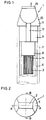
- the reference numeral 1 shown in Figures 1 through 9 designates an improved liquid applicator according to a concrete embodiment of the invention.
- the liquid applicator 1 according to the invention comprises a holder unit 5 which is provided with a roller 2 and a relay core 3, an ink pool 6, and a pen shaft 7.
- the holder 5 is secured to the tip of the ink pool 6, still more the pen shaft 7 is secured to the outside of the ink pool 6.
- the ink pool 6 and the pen shaft 7 are exactly identical to those which are used for any conventional ball pen, where the ink pool 6 and the pen shaft 7 are respectively made from synthetic resin and cylindrically formed.
- the ink pool 6 internally stores water-soluble ink available for any conventional ball pen. More particularly, the ink pool 6 contains gelled water-soluble ink available for any conventional ball pen such as the one containing a maximum of 8000CPS of viscosity. Either of the gel led water-soluble ink and water-soluble ink uses water as the main solvent. Conventional oily ink uses organic solvent such as phenyl cellosolve or benzyl alcohol for example.
- ink available for aqueous ball pen uses waters solvent.
- Ink available for an oily ball pen contains 10000 through 30000CPS of high-grade viscosity, whereas ink of an aqueous ball pen contains viscosity lower than that of oily ink.
- Ink available for an aqueous ball pen is roughly classified into two groups according to the difference in the performance of viscosity. The one is such an ink capable of performing "Newton" fluxion (viscosity remains constant according to the degree of fluxion). Concretely, viscosity in the ink pool and the ball housing is identical. Normally, ink containing 5 through 2000CPS of viscosity is used.
- the other group of ink contains viscosity having property to vary itself according to fluxion of ink.
- ink belonging to the latter group contains 2000 through 8000CPS of viscosity in the ink pool.
- viscosity is sharply reduced to a maximum of 10CPS.
- the latter ink is called “thixotropic ink”.
- water-soluble ink added with gelling agent containing thixotropic property is generally called “water-soluble gelled ink”
- the liquid applicator 1 incorporates a hollow roller 2 having a through-hole 4 in the center.
- the invention has introduced such a hollow roller 2. More particularly, the light-weight roller 2 prevents unwanted clearance from being generated between a tip aperture 15 of a roller-storing portion 18 and the roller 2 itself otherwise caused by fall of the roller 2 into the roller-storing portion 18 when the roller 2 is laid atop.
- Another important effect is to prevent the roller 2 from dropping off from the holder housing when the liquid applicator 1 receives shock.
- the invention permits use of copper, nickel, zinc alloy, or copper alloy such as brass, stainless steel, or resin free of metamorphosis to be caused by ink, for composing the roller 2.
- the through-hole 4 in the center of the roller 2 is generally formed by executing a cutting process.
- Ratio between the inner and outer diameters of the roller 2 approximately ranges from 0.5:1 to 0.8:1. Practical ratio is mainly selected according to rigidity of the roller 2. Concretely, as far as own rigidity is durable, it is desired that the roller 2 be provided with the through-hole 4 having as wide diameter as possible. Expansion of the size of the through-hole unavoidably causes mass of the roller to decrease. Based on this reason, the wider the diameter of the through-hole 4 of the roller 2, the less the inertia force generated in the roller when incurring shock thereto, and thus the roller 2 can hardly be disengaged from the liquid applicator.
- ratio relationship between the inner and outer diameters and the weight of the roller 2 is shown in the following table.
- Ratio of inner/outer diameters Ratio of weight 0.5 : 1 0.75 0.7 : 1 0.51 0.75 : 1 0.44 0.8 : 1 0.36 Note: The table represents weight ratio when actual weight of a solid roller is 1.
- the relay core 3 consists of a bundle of polyacrylic or nylon fibers.
- the invention also permits use of a bundle of tubular resinous filaments, or a solid of polyacetal-resin or nylon-resin each having a fine through-hole in the axial direction, for composing the relay core 3.
- the relay core 3 is of circular-cylindrical form, where only the tip portion is flatly chipped off.
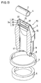
- the holder 5 holds the roller 2 and the relay core 3, which is formed by an injection molding of polypropylene resin or the like. External configuration of the holder 5 is sectioned into 3 parts including an ink supply unit 8, a pen shaft insert 9, and anexposed portion 10.
- the ink supply unit 8 has circular sectionwhose external circumference is substantially equal to the inner diameter of the ink pool 6.
- An ink inlet hole 11 is formed through the bottom of the ink supply unit 8.
- the pen-shaft insert 9 is also of circular section, the diameter is slightly wider than that of the ink supply unit 8. Outer diameter of the pen-shaft insert 9 is almostequal to the inner diameter of the pen shaft 7.
- a pair of grooves12 are formed in the pen-shaft insert 9 in the axial direction thereof. The grooves 12 jointly function to equalize atmospheric pressure inside and outside of the pen-shaft insert 9 so that ink from the ink supply unit 8 can smoothly flow into the holder 5.
- the exposed portion 10 of the holder 5 has circular section across the border of the pen-shaft insert 9. Structurally, the exposed portion 10 is tapered, where the tip portion is of ridge-like form. More particularly, the tip of the exposed portion 10 extends itself in the vertical direction against the center axis, where the tip surface has very narrow width. In addition, a rectangularly shaped aperture 15 is formed at the tip of the exposed portion 10. Width of the tip-aperture 15 is slightly narrower than the diameter of the roller 2.
- the ink inlet hole 11 and the tip aperture 15 of the holder 5 are interlinked with each other via an ink passage hole 17 and a roller-storing portion 18.
- the ink passage hole 17 is cylindrically formed on the part of the ink inlet hole 11. Local portion of the ink passage hole 17 close to the roller storing portion 18 is gradually flattened (in other words, the interior of the holder 5 gradually be thick), whereas tip of the ink passage hole 17 opens to the roller-storing portion 18.
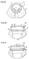
- the roller-storing portion 18 itself is a portion for rotatably accommodating the roller 2 therein, As shown in Figures 4 and 7, the roller-storing portion 18 has polygonal section surrounded by vertically flat edge surfaces 22 and circumferential surface 24. Inner dimension of the edge surfaces 22 is greater than the total length of the roller 2 by approximately one 100th millimeter, Accordingly, even when the roller 2 is mounted, both edge surfaces 22 do not press the corresponding edge surfaces of the roller 2.
- Circumferential surface 24 is composed of four continuous surfaces.
- the circumferential surface 24 has a pair of surfaces 25 being in parallel with axial line and a pair of double-step tapered surfaces 28 and 29 being continuous to the axially parallel surfaces 25.
- the tapered surface 28 being continuous to the axially parallel surfaces 25 is acute angled
- the other tapered surface 29 being continuous to the tapered surface 28 is obtuse angled
- the tapered surfaces 28 and 29 respectively converge themselves in the direction of the border between the roller-storing portion 18 and the ink inlet hole 17.
- a number of shallow grooves are formed on the tapered surface 29.
- the roller 2 is pressedly inserted in the roller-storing portion 18 via the tip aperture 15 of the holder 5.
- the relay core 3 is pressedly inserted from the ink inlet hole 11 of the holder 5, where the tip of the relay core 3 projects itself inside of the roller-storing portion 18.
- the tip of the relay core 3 constantly remains in contact with circumferential surface of the roller 2 so that the roller 2 can be pressed in the direction of the tip aperture 15.
- the circumferential surface 24 of the roller 2 closely adheres to longitudinal local domains of the aperture edge of the tip aperture 15, and thus, no clearance is formed in the aperture 15.
- the roller storing portion 18 is fully shielded from external atmosphere, thus maintaining air-tightness.
- the exposed portion of the roller 2 is pressed against a paper surface by downwardly holding the roller 2.
- ink flows into the holder 5 via the relay core 3, and then the roller-storing portion 18 is filled with ink,
- the roller 2 When the exposed portion of the roller 2 is pressed against a paper surface, the roller 2 slightly sinks itself in the roller-storing portion 18 in resistance against pressure from the relay core 3, and then, the roller 2 slightly comes into contact with the tapered surfaces 28 and 29 of the roller-storing portion 18. When this condition is entered, minimal clearance is generated between the roller 2 and the tip aperture 15.
- the roller 2 rolls itself over the paper surface to permit outgoing ink to be transferred onto the paper surface.
- liquid applicator 1 embodied by the invention, even when the liquid applicator 1 is vertically placed in a pen stand after completing a drawing work by putting the roller 2 atop, ink can be prevented from flowing into the ink pool 6.
- the roller 2 After completing a drawing work, the roller 2 is pressed in the direction of the tip aperture 15 by the relay core 3 to fully close the tip aperture 15. This in turn securely prevents air from the tip aperture 15 from permeating into the roller-storing portion 18 and also prevents air from being replaced inside of the roller-storing portion 18, thus eventually preventing ink from flowing into the ink pool 6 otherwise caused by effect of atmospheric pressure. Furthermore, since the tip aperture 15 is fully closed by the roller 2, ink inside of the roller-storing portion 18 cannot be dried. In consequence, whenever resuming the drawing with the inventive liquid applicator 1, ink flows out very smoothly from the initial touch against a paper surface.
- the ink passage hole 17 remains being closed by the relay core 3 functioning as a lid, and thus, ink pooled in the roller 2 and the roller-storing portion 18 cannot flow downwardly into the ink pool 6 in practical effect.
- the liquid applicator 1 according to the invention strongly supports the roller 2 without causing the roller 2 to jump out of the holder 5 even when receiving strong shock.
- roller 2 of the liquid applicator 1 related to the invention is hollow, it contains minimal mass, and thus, the roller 2 merely generates negligible inertia force. In consequence, even when receiving substantial shock, the roller 2 remains unaffected without being dropped off from the holder 5,
- a liquid applicator 1 In order to check and confirm practical effect of the inventive liquid applicator 1, inventors experimentally fabricated a liquid applicator 1 by internally providing a roller made of stainless steel having 4mm of length, 2mm of diameter, and inner diameter being 75% against the outer diameter. For comparative example, inventors also experimentally fabricated a liquid applicator incorporating a solid roller having length and external configuration exactly identical to the hollow roller embodied by the invention. As a result of drop test done by dropping down both samples from a 1 meter high position, the comparative solid roller was then disengaged from the liquid applicator prepared for the comparative test, whereas the hollow roller 2 of the inventive liquid applicator 1 remained unaffected as of the firmly secured condition.
- the roller 2 is secured to the holder 5 by arranging the tip aperture 15 of the roller storing portion 18 to be narrower than the width of the roller 2, and also by causing the circumferential surface of the roller 2 to come into contact with the back surface of the tip aperture 15 of the roller-storing portion 18.
- a pair of semispherical projections 43 are provided on both sides of the interior of the roller-storing portion 18 at positions at which the edge surfaces of the roller 2 respectively come into contact therewith.
- the above projections 43 respectively transform themselves, and then, when the roller 2 is set to the correct position, the projections 43 are respectively inserted in the through-hole 4.
- the liquid applicator 50 shown in Figure 12 prevents the roller 2 from being disengaged from the holder 53 by applying a shaft 51 in place of the above-referred projections 43.
- the roller-storing portion 18 of the holder 53 introduced to this embodiment is provided with a through-hole 54.
- the roller 2 is disposed inside of the roller-storing portion 18.
- a shaft 51 extends itself between the through-hole 4 of the roller 2 and the roller storing portion 18.
- the shaft 51 is disposed solely for the purpose of preventing the roller 2 from being disengaged from the holder 53, and conversely, provision of the shaft 51 is not based on such an intent to have it serve as a shaft for rotating the roller 2. Accordingly, diameter of the shaft 51 is obviously narrower than that of the through-hole 4 of the roller 2.
- Fine holes of the porous roller 60 may contain continuous foam or independent foam, and yet, the roller 60 may be provided with smooth surface or projections and recesses.
- the roller 60 has smooth surface, seat surface of the roller-storing portion 18 smoothly slips in conjunction with the roller 2 while writing letters with the inventive liquid applicator 1, thus permitting the roller 2 to smoothly rotate itself.
- projections and recesses on the surface of the roller 60 ink properly spreads over the roller 2.
- the roller-storing portion is provided with double-step tapered surfaces.
- the roller 2 is pressed by the relay core 3, and yet, the tip aperture remains fully being closed.
- Figures 14 through 21 respectively exemplify further embodiments of the invention by applying the above novel art to a liquid applicator devoid of the relay core 3.
- the liquid applicator 70 shown in Figures 14 through 19 differs from the liquid applicator 1 shown in Figures 1 through 9 in that no relay core is built in the liquid applicator 70.
- the liquid applicator 70 is provided with parallel grooves at the border between the roller-storing portion 18 and the ink passage hole 17.
- a pair of projections 43 are formed inside of the roller-storing portion 18 by way of engagement with a through-hole 4 of the roller 2.
- a shaft 51 is inserted through a through-hole 4 of the roller 2 by way of being supported by a hole 54 formed in the roller-storing portion 18.
- any of the above-referred liquid applicators 70, 80, and 90 disclosed in Figures 14 through 21 is resistant against shock without causing the roller 2 to jump out of the roller-storing portion. Since stored ink rarely drops into the ink pool, any of the above liquid applicators according to the invention provides satisfactory flow of writing from the initial touch on a paper surface.
Landscapes
- Pens And Brushes (AREA)
Applications Claiming Priority (6)
| Application Number | Priority Date | Filing Date | Title |
|---|---|---|---|
| JP11370494A JP3310457B2 (ja) | 1994-04-27 | 1994-04-27 | 塗布具 |
| JP113704/94 | 1994-04-27 | ||
| JP11370394A JP3310456B2 (ja) | 1994-04-27 | 1994-04-27 | 塗布具 |
| JP113703/94 | 1994-04-27 | ||
| JP12432194A JP3310458B2 (ja) | 1994-05-14 | 1994-05-14 | 塗布具 |
| JP124321/94 | 1994-05-14 |
Publications (2)
| Publication Number | Publication Date |
|---|---|
| EP0679536A2 true EP0679536A2 (de) | 1995-11-02 |
| EP0679536A3 EP0679536A3 (de) | 1996-02-07 |
Family
ID=27312565
Family Applications (1)
| Application Number | Title | Priority Date | Filing Date |
|---|---|---|---|
| EP94114182A Withdrawn EP0679536A3 (de) | 1994-04-27 | 1994-09-09 | Flüssigkeitsauftragegerät. |
Country Status (1)
| Country | Link |
|---|---|
| EP (1) | EP0679536A3 (de) |
Cited By (1)
| Publication number | Priority date | Publication date | Assignee | Title |
|---|---|---|---|---|
| WO2004048122A1 (en) * | 2002-11-27 | 2004-06-10 | Benjamin Amit | Improved writing and marking pen |
Family Cites Families (8)
| Publication number | Priority date | Publication date | Assignee | Title |
|---|---|---|---|---|
| CH232387A (fr) * | 1943-06-08 | 1944-05-31 | Cambria Sebastien | Instrument pour tracer des lignes parallèles. |
| GB643626A (en) * | 1948-06-16 | 1950-09-20 | Mieczyslaw Maciejewski | Hand moistener, shaped as a fountain pen for damping envelopes, stamps and similar gummed labels |
| CH455568A (de) * | 1966-11-21 | 1968-07-15 | Simon Peter | Zeichenstift |
| FR2160697A1 (de) * | 1971-11-22 | 1973-07-06 | Gulesian Pierre | |
| US4129391A (en) * | 1975-01-23 | 1978-12-12 | Gamacher Robert J | Integral applicator structure |
| DE2709852A1 (de) * | 1977-03-07 | 1978-09-14 | Diemann Hans Dieter Dipl Ing | Zeichenspitze |
| DE3121948A1 (de) * | 1981-06-03 | 1982-12-23 | Ideee Design Gmbh, 5600 Wuppertal | Korrekturstift |
| DE8520507U1 (de) * | 1985-07-16 | 1985-08-29 | Glasa, Stefan, 2000 Hamburg | Markierungsstift zur Kennzeichnung |
-
1994
- 1994-09-09 EP EP94114182A patent/EP0679536A3/de not_active Withdrawn
Cited By (1)
| Publication number | Priority date | Publication date | Assignee | Title |
|---|---|---|---|---|
| WO2004048122A1 (en) * | 2002-11-27 | 2004-06-10 | Benjamin Amit | Improved writing and marking pen |
Also Published As
| Publication number | Publication date |
|---|---|
| EP0679536A3 (de) | 1996-02-07 |
Similar Documents
| Publication | Publication Date | Title |
|---|---|---|
| US5709492A (en) | Liquid applicator | |
| US4416201A (en) | Ink roller assembly with capillary ink supply | |
| US5483719A (en) | Hair brush with porous polytetrafluoroethylene body | |
| US5813787A (en) | Nib units for pens | |
| CA1076066A (en) | Writing pen having finned collector including a weir | |
| JP5940898B2 (ja) | ボールペン | |
| CN1972812A (zh) | 液体供应装置 | |
| US6132124A (en) | Ink follower for aqueous ballpoint pen using gel-like material and solid piece | |
| US6048054A (en) | Ink replenishing apparatus and ink replenishing method for ink-jet printing ink cartridge | |
| EP0679536A2 (de) | Flüssigkeitsauftragegerät | |
| JP7011893B2 (ja) | 筆記具 | |
| US6887008B2 (en) | Ballpoint pen tip, ballpoint pen utilizing the ballpoint pen tip and method of manufacturing the ballpoint pen tip | |
| US6312180B1 (en) | Applicator for correction fluid | |
| US2847975A (en) | Writing instrument | |
| WO1994005511A1 (en) | Writing instrument barrel and method | |
| EP0186067A2 (de) | Werkzeug für spanabhebendes Bearbeiten | |
| CN110759142B (zh) | 一种薄膜印刷机上的纸卷装夹料架 | |
| CN2392673Y (zh) | 改良型可加油墨的含墨印章 | |
| WO1997003845A1 (en) | Writing tool | |
| US3335706A (en) | Pen cartridge | |
| JP2022152864A (ja) | 色鉛筆芯と、それを収容した替芯ケースとを具備する、替芯製品 | |
| KR100360613B1 (ko) | 볼식 액체용기의 선단팁 | |
| JPH0612943Y2 (ja) | 印 判 | |
| JP2001063277A (ja) | 液体塗布具 | |
| CN223877770U (zh) | 毛笔 |
Legal Events
| Date | Code | Title | Description |
|---|---|---|---|
| PUAI | Public reference made under article 153(3) epc to a published international application that has entered the european phase |
Free format text: ORIGINAL CODE: 0009012 |
|
| AK | Designated contracting states |
Kind code of ref document: A2 Designated state(s): DE FR GB |
|
| PUAL | Search report despatched |
Free format text: ORIGINAL CODE: 0009013 |
|
| AK | Designated contracting states |
Kind code of ref document: A3 Designated state(s): DE FR GB |
|
| 17P | Request for examination filed |
Effective date: 19960619 |
|
| 17Q | First examination report despatched |
Effective date: 19970809 |
|
| STAA | Information on the status of an ep patent application or granted ep patent |
Free format text: STATUS: THE APPLICATION IS DEEMED TO BE WITHDRAWN |
|
| 18D | Application deemed to be withdrawn |
Effective date: 19980120 |