EP0679613B1 - Biege- und Härtevorrichtung für Glasscheiben - Google Patents
Biege- und Härtevorrichtung für Glasscheiben Download PDFInfo
- Publication number
- EP0679613B1 EP0679613B1 EP95106204A EP95106204A EP0679613B1 EP 0679613 B1 EP0679613 B1 EP 0679613B1 EP 95106204 A EP95106204 A EP 95106204A EP 95106204 A EP95106204 A EP 95106204A EP 0679613 B1 EP0679613 B1 EP 0679613B1
- Authority
- EP
- European Patent Office
- Prior art keywords
- tempering
- bending
- rollers
- conveyor
- boxes
- Prior art date
- Legal status (The legal status is an assumption and is not a legal conclusion. Google has not performed a legal analysis and makes no representation as to the accuracy of the status listed.)
- Expired - Lifetime
Links
- 239000011521 glass Substances 0.000 title claims abstract description 42
- 238000005496 tempering Methods 0.000 title claims abstract description 42
- 238000005452 bending Methods 0.000 title claims description 44
- 238000003825 pressing Methods 0.000 description 4
- 239000000463 material Substances 0.000 description 3
- 239000000725 suspension Substances 0.000 description 3
- 238000003462 Bender reaction Methods 0.000 description 2
- 239000011248 coating agent Substances 0.000 description 2
- 238000000576 coating method Methods 0.000 description 2
- 230000003287 optical effect Effects 0.000 description 2
- 238000013021 overheating Methods 0.000 description 2
- 230000006978 adaptation Effects 0.000 description 1
- 239000007795 chemical reaction product Substances 0.000 description 1
- 238000010276 construction Methods 0.000 description 1
- 238000001816 cooling Methods 0.000 description 1
- 230000003247 decreasing effect Effects 0.000 description 1
- 230000001419 dependent effect Effects 0.000 description 1
- 230000001627 detrimental effect Effects 0.000 description 1
- 238000010438 heat treatment Methods 0.000 description 1
- 238000004519 manufacturing process Methods 0.000 description 1
- 230000010355 oscillation Effects 0.000 description 1
- 230000001737 promoting effect Effects 0.000 description 1
- 238000010791 quenching Methods 0.000 description 1
- 230000000171 quenching effect Effects 0.000 description 1
- 238000007761 roller coating Methods 0.000 description 1
Images
Classifications
-
- C—CHEMISTRY; METALLURGY
- C03—GLASS; MINERAL OR SLAG WOOL
- C03B—MANUFACTURE, SHAPING, OR SUPPLEMENTARY PROCESSES
- C03B27/00—Tempering or quenching glass products
- C03B27/04—Tempering or quenching glass products using gas
- C03B27/044—Tempering or quenching glass products using gas for flat or bent glass sheets being in a horizontal position
- C03B27/0442—Tempering or quenching glass products using gas for flat or bent glass sheets being in a horizontal position for bent glass sheets
- C03B27/0447—Tempering or quenching glass products using gas for flat or bent glass sheets being in a horizontal position for bent glass sheets the quench unit being variably adaptable to the bend of the sheet
-
- C—CHEMISTRY; METALLURGY
- C03—GLASS; MINERAL OR SLAG WOOL
- C03B—MANUFACTURE, SHAPING, OR SUPPLEMENTARY PROCESSES
- C03B23/00—Re-forming shaped glass
- C03B23/02—Re-forming glass sheets
- C03B23/023—Re-forming glass sheets by bending
- C03B23/03—Re-forming glass sheets by bending by press-bending between shaping moulds
- C03B23/033—Re-forming glass sheets by bending by press-bending between shaping moulds in a continuous way, e.g. roll forming, or press-roll bending
-
- C—CHEMISTRY; METALLURGY
- C03—GLASS; MINERAL OR SLAG WOOL
- C03B—MANUFACTURE, SHAPING, OR SUPPLEMENTARY PROCESSES
- C03B40/00—Preventing adhesion between glass and glass or between glass and the means used to shape it, hold it or support it
- C03B40/005—Fabrics, felts or loose covers
Definitions
- the present invention relates to a bending and tempering station for glass sheets, comprising a roll conveyor in which the relative vertical position of the rolls is adjustable for arching the conveyor to a curvature corresponding to a desired degree of bending about a bending axis extending transversely to the glass sheet advancing direction i.e. parallel to the rolls, lower tempering boxes having top surfaces provided with tempering orifices, and upper tempering boxes having bottom surfaces provided with tempering orifices, said tempering boxes being movable for bringing said top and bottom surfaces in conformity to the arching of the conveyor.
- This type of apparatus is prior known from the Applicant's Patent publications US-A-4,881,962 and US-A-5,057,137. This apparatus has proved extremely useful in the production of bent and tempered construction glass.
- EP-A1- 133 144 discloses a similar apparatus for bending and quenching of glass sheets which are arranged lengthwise on a curved profile which turns upside.
- the bending of a glass sheet is based on gravitational bending in a bending and tempering station located outside a heating furnace. Therefore, it is sometimes necessary to overheat the glass relative to a required tempering temperature since the glass temperature falls before the glass has completely bent to its desired configuration and the glass tempering can be commenced.
- the cooling of glass is typically in the order of 10°C - 25°C.
- a characterizing feature for this so-called overheating is that the optical errors of glass are accentuated and are more perceivable in the end product.
- An object of the invention is to improve the above prior known apparatus in a manner that such detrimental overheating can be omitted for decreasing the temperature of a glass sheet coming out of a furnace and improving the glass optics.
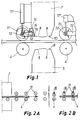
- a bending and tempering station 2 Downstream of a furnace 1 lies a bending and tempering station 2 provided with a conveyor 3 consisting of rolls 4. Below a glass sheet carried by the rolls 4 are tempering boxes 5 and thereabove are tempering boxes 7.
- the tempering boxes 5 have top surfaces 9 provided with nozzle orifices 6 and the tempering boxes 7 have bottom surfaces 10 provided with nozzle orifices 8. Nozzles enclosed in the tempering boxes 5 and 7 are not shown and the design and configuration thereof can be varied in many ways.
- the conveyor 3 can be arched to a curvature corresponding to a degree of bending desired for the glass. This can be effected by any mechanism capable of moving the rolls 4 relative to each other in vertical direction.
- the nozzle boxes 5 and 7 are adpted to be movable in a corresponding manner, such that the upper and lower array of boxes have a curvature matching that of the conveyor 3.
- the box surfaces 9 and 10 maintain essentially the same distance from the glass surface, whereby the glasses can be tempered effectively and uniformly irrespective of their degree of bending.
- the upper tempering boxes 7 are fitted with a number of press rollers 11 adapted to be movable by means of a pneumatic cylinder 17 between an upper rest position and a lower working position.
- the axially short and lightweight rollers 11 are journalled onto a stub axle 13 which is fastened to the end of the piston rod of cylinder 17.
- Linked to the axle 13 is also a swinging arm 12 limiting the vertical movement of said axle 13.
- the swinging arm 12 is fastened by means of a hinge pin 14 to a lug included in the side surface of box 7.
- Limiting abutments 15 and 16 define the boundaries for the swinging motion of arm 12.
- the bottom position limiting abutment 15 is preferably adjustable. In the bottom position, the bottom surface of roller 11 is typically at a distance of 2-3 mm from the plane defined by the top surface of rolls 4.
- the roller 11 may have a fixed top position, e.g. 8-10 mm from the plane defined by the top surface of rolls 4.
- the adjustment of the air pressure of pneumatic cylinder 17 can be used for achieving a desired pressing force for promoting the glass bending. If desired, the pressing force can also be adjusted during the course of bending.
- the pneumatic cylinder 17 has a diameter of e.g. 8-10 mm and a length which preferably approximately 5 times the diameter for providing a suitable resilience.
- the simultaneous control of all pneumatic cylinders 17 can be used for operating all rollers 11 simultaneously between said top and bottom end positions.
- the press wheels 11 are in their top position slightly off the glass surface or they can also be in a light contact therewith.
- the press wheels 11 are provided with a desired and adjustable downforce forcing the glass to conform to the rolls 4 of the flexing conveyor.
- the glass reciprocates in an oscillating fashion during the course of bending.
- the press rollers 11 and conveyor rolls 4 are on top of each other and, in the bottom position of rollers 11, the distance therebetween is slightly less than the thickness of a glass sheet to be bent.
- the rollers shift a small distance upwards against the force of the pneumatic spring 17.
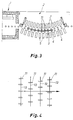
- Fig. 3 illustrates a situation in which the glass has reached a certain degree of bending.
- the tempering blast is commenced while the glass continues oscillation between rolls 4 and rollers 11.
- the upper press rollers 11 are lifted and returned to their top position.
- the bottom position of rollers 11 is a working position and the top position is a rest position.
- Fig. 4 illustrates the disposition of press rollers, selected so as not to form successive rows relative to the glass advancing direction.
- the press wheels are structurally light and well journalled for free rotation.
- the wheels are provided e.g. with plastic bodies and on their peripheries with a fibrous coating of a material temporarily resistant to a high temperature (about 630°C).
- the coating material can be any material used in roller coatings.
- the resilient suspension and adjustable pressing force of rollers provide an essential advantage over conventional benders in which the roller axles are fixedly connected to tempering boxes.
- the invention is not limited to the above exemplary embodiment but its structural details can be varied in many ways.
- the pneumatic spring 17 can be replaced with other types of springs.
- the restriction of the movement of rollers 11 to a top and bottom position can be provided in a plurality of ways.
- the press rollers or wheels need not necessarily be suspended directly to nozzle boxes 7 but the suspension can be indirect.
- One and the same horizontal axle 13 can also be used for journalling a plurality of press wheels 11 supported by one or more pneumatic springs 17.
Landscapes
- Chemical & Material Sciences (AREA)
- Engineering & Computer Science (AREA)
- Materials Engineering (AREA)
- Organic Chemistry (AREA)
- Physics & Mathematics (AREA)
- Thermal Sciences (AREA)
- Re-Forming, After-Treatment, Cutting And Transporting Of Glass Products (AREA)
- Joining Of Glass To Other Materials (AREA)
- Glass Compositions (AREA)
- Polarising Elements (AREA)
Claims (7)
- Biege-und-Härt-Station für Glasscheiben, die einen Rollenförderer (3), bei dem die vertikale Position der Rollen (4) zueinander verstellt werden kann, um den Förderer zu einer Krümmung zu wölben, die einem gewünschten Grad der Biegung entspricht, untere Härtkästen (5) mit Oberseiten (9), die mit Härtdüsen (6) versehen sind, und obere Härtkästen (7) mit Unterseiten (10) umfaßt, die mit Härtdüsen (8) versehen sind, wobei die Härtkästen (5, 7) bewegt werden können, um die Ober- und die Unterseite (9, 10) an die Wölbung des Förderers (3) anzupassen, dadurch gekennzeichnet, daß eine Reihe von Preßwalzen (11) an den oberen Härtkästen (7) angebracht sind, wobei die Walzen (11) zwischen einer oberen Ruheposition und einer unteren Arbeitsposition bewegt werden können, in der die Walzen (11) durch eine Federkraft elastisch nach unten gedrückt werden.
- Biege-und-Härt-Station nach Anspruch 1, dadurch gekennzeichnet, daß die Federkraft mit Luftdruckfedern (17) erzeugt wird, die jeweils zu einer Walze (11) gehören.
- Biege-und-Härt-Station nach Anspruch 2, dadurch gekennzeichnet, daß die Druckluftfedern Druckluftzylinder (17) sind, die nicht nur die Federkraft erzeugen, sondern gleichzeitig auch die Walzen (11) zwischen der Ruheposition und der Arbeitsposition bewegen.
- Biege-und-Härt-Station nach einem der Ansprüche 1-3, dadurch gekennzeichnet, daß in der Arbeitsposition der Abstand des untersten Punktes der Walze (10) zu einer Förderhöhe, die durch den höchsten Punkt der Förderrollen (4) bestimmt wird, ungefähr 2-3 mm beträgt, und der entsprechende Abstand in der Ruheposition ungefähr 8-10 mm beträgt, wenn sich die Härtkästen (5, 7) in einer Härtposition befinden.
- Biege-und-Härt-Station nach einem der vorangehenden Ansprüche 1 bis 4, dadurch gekennzeichnet, daß die Walzen (11) aus der Ruheposition in die Arbeitsposition bewegt werden, nachdem eine zu biegende Glasscheibe aus einem Ofen (1) auf den Förderer (3) und unter die Walzen (11) gelangt ist.
- Biege-und-Härt-Station nach einem der Ansprüche 1-5, dadurch gekennzeichnet, daß eine Vielzahl von Preßwalzen (11) an einer gemeinsamen horizontalen Achse (13) angebracht ist, die mit dem Druckluftzylinder (17) vertikal hin und her bewegt wird.
- Biege-und-Härt-Station nach einem der Ansprüche 1-6, gekennzeichnet durch Begrenzungsanschläge (15, 16), die die Arbeitsposition und die Ruheposition der Walzen (11) bestimmen.
Applications Claiming Priority (2)
| Application Number | Priority Date | Filing Date | Title |
|---|---|---|---|
| FI941931A FI95236C (fi) | 1994-04-26 | 1994-04-26 | Lasilevyjen taivutus- ja karkaisuosasto |
| FI941931 | 1994-04-26 |
Publications (3)
| Publication Number | Publication Date |
|---|---|
| EP0679613A2 EP0679613A2 (de) | 1995-11-02 |
| EP0679613A3 EP0679613A3 (de) | 1996-04-03 |
| EP0679613B1 true EP0679613B1 (de) | 1999-12-22 |
Family
ID=8540595
Family Applications (1)
| Application Number | Title | Priority Date | Filing Date |
|---|---|---|---|
| EP95106204A Expired - Lifetime EP0679613B1 (de) | 1994-04-26 | 1995-04-25 | Biege- und Härtevorrichtung für Glasscheiben |
Country Status (10)
| Country | Link |
|---|---|
| US (1) | US5443609A (de) |
| EP (1) | EP0679613B1 (de) |
| JP (1) | JP3778965B2 (de) |
| CN (1) | CN1065839C (de) |
| AT (1) | ATE187953T1 (de) |
| AU (1) | AU693514B2 (de) |
| CA (1) | CA2146628C (de) |
| DE (1) | DE69514029T2 (de) |
| FI (1) | FI95236C (de) |
| RU (1) | RU95106672A (de) |
Families Citing this family (17)
| Publication number | Priority date | Publication date | Assignee | Title |
|---|---|---|---|---|
| EP0778246B1 (de) * | 1995-12-07 | 1999-08-18 | Tamglass Engineering Oy | Verfahren und Vorrichtung zum Biegen und Tempern von Glastafeln |
| WO1998022400A1 (fr) * | 1996-11-21 | 1998-05-28 | Asahi Glass Company Ltd. | Procede et appareil permettant de cintrer une plaque de verre |
| FI101146B (fi) * | 1997-06-03 | 1998-04-30 | Tamglass Ltd Oy | Menetelmä uunista karkaisuosastoon tai taivutus- ja karkaisuosastoon s iirretyn lasilevyn pysäyttämiseksi |
| WO2004035492A1 (ja) * | 2002-10-21 | 2004-04-29 | Nippon Sheet Glass Co., Ltd. | 曲げ強化ガラス板の製造方法及びその装置 |
| US7287401B2 (en) * | 2004-06-10 | 2007-10-30 | Glasstech, Inc. | System and method for cylindrically forming glass sheets |
| US7228717B2 (en) * | 2004-06-10 | 2007-06-12 | Glasstech, Inc. | Apparatus for glass sheet forming with cross curvature |
| US7086252B2 (en) * | 2004-06-10 | 2006-08-08 | Glasstech, Inc. | System and method for continuous forming of glass sheets |
| US7744955B2 (en) * | 2005-08-02 | 2010-06-29 | Guardian Industries Corp. | Method of thermally tempering coated article with transparent conductive oxide (TCO) coating using flame(s) in tempering furnace adjacent TCO to burn off oxygen and product made using same |
| US7597964B2 (en) * | 2005-08-02 | 2009-10-06 | Guardian Industries Corp. | Thermally tempered coated article with transparent conductive oxide (TCO) coating |
| US20070029186A1 (en) * | 2005-08-02 | 2007-02-08 | Alexey Krasnov | Method of thermally tempering coated article with transparent conductive oxide (TCO) coating using inorganic protective layer during tempering and product made using same |
| US8298380B2 (en) * | 2006-05-23 | 2012-10-30 | Guardian Industries Corp. | Method of making thermally tempered coated article with transparent conductive oxide (TCO) coating in color compression configuration, and product made using same |
| ITRM20120385A1 (it) * | 2012-08-03 | 2014-02-04 | Antonio Mazzaroppi | Apparato per la piegatura di lastre di vetro. |
| EP2692704B1 (de) * | 2012-08-03 | 2018-10-24 | Antonio Mazzaroppi | Vorrichtung zum Biegen einer Glasscheibe, insbesondere mit dynamischer Anpassung der Glasscheibendicke |
| ITRM20120386A1 (it) * | 2012-08-03 | 2014-02-04 | Antonio Mazzaroppi | Apparato di piegatura di una lastra di vetro, con regolazione dinamica dello spessore della lastra. |
| WO2014167894A1 (ja) * | 2013-04-10 | 2014-10-16 | 日本電気硝子株式会社 | 曲面形状を有するガラス板の製造方法及び曲面形状を有するガラス板 |
| FI20135728A7 (fi) | 2013-07-03 | 2015-01-04 | Taifin Glass Machinery Oy | Menetelmä lasilevyn lämmittämiseksi ja lasinkarkaisu-uuni |
| FI126859B (fi) * | 2016-03-18 | 2017-06-30 | Glaston Finland Oy | Menetelmä ja laite lasilevyn taivuttamiseksi ja karkaisemiseksi |
Family Cites Families (6)
| Publication number | Priority date | Publication date | Assignee | Title |
|---|---|---|---|---|
| US481962A (en) * | 1892-09-06 | Method of manufacturing horseshoe-nails | ||
| US4586946A (en) * | 1983-02-07 | 1986-05-06 | Carl Kramer | Equipment for curving glass sheets |
| FR2549465B1 (fr) * | 1983-07-20 | 1985-09-20 | Saint Gobain Vitrage | Installation de bombage et de trempe de feuilles de verre |
| FI76313C (fi) * | 1986-09-22 | 1988-10-10 | Kyro Oy | Foerfarande och anordning foer boejning och tempering av glasskivor. |
| US4822398A (en) * | 1987-08-07 | 1989-04-18 | Mcmaster Harold | Glass bending and tempering apparatus |
| US5009693A (en) * | 1989-10-04 | 1991-04-23 | Muirfield Holdings L.P. | Method and apparatus for bending glass |
-
1994
- 1994-04-26 FI FI941931A patent/FI95236C/fi not_active IP Right Cessation
- 1994-05-11 US US08/240,614 patent/US5443609A/en not_active Expired - Lifetime
-
1995
- 1995-04-06 AU AU16303/95A patent/AU693514B2/en not_active Expired
- 1995-04-07 CA CA002146628A patent/CA2146628C/en not_active Expired - Lifetime
- 1995-04-21 JP JP12057595A patent/JP3778965B2/ja not_active Expired - Fee Related
- 1995-04-25 DE DE69514029T patent/DE69514029T2/de not_active Expired - Lifetime
- 1995-04-25 CN CN95104781A patent/CN1065839C/zh not_active Ceased
- 1995-04-25 RU RU95106672/03A patent/RU95106672A/ru unknown
- 1995-04-25 EP EP95106204A patent/EP0679613B1/de not_active Expired - Lifetime
- 1995-04-25 AT AT95106204T patent/ATE187953T1/de not_active IP Right Cessation
Also Published As
| Publication number | Publication date |
|---|---|
| DE69514029T2 (de) | 2000-04-27 |
| AU1630395A (en) | 1995-11-02 |
| FI95236C (fi) | 1996-01-10 |
| FI941931A0 (fi) | 1994-04-26 |
| EP0679613A2 (de) | 1995-11-02 |
| DE69514029D1 (de) | 2000-01-27 |
| US5443609A (en) | 1995-08-22 |
| CA2146628A1 (en) | 1995-10-27 |
| CN1065839C (zh) | 2001-05-16 |
| EP0679613A3 (de) | 1996-04-03 |
| RU95106672A (ru) | 1997-01-27 |
| ATE187953T1 (de) | 2000-01-15 |
| CA2146628C (en) | 2005-12-20 |
| AU693514B2 (en) | 1998-07-02 |
| FI95236B (fi) | 1995-09-29 |
| JP3778965B2 (ja) | 2006-05-24 |
| JPH07291646A (ja) | 1995-11-07 |
| CN1112907A (zh) | 1995-12-06 |
Similar Documents
| Publication | Publication Date | Title |
|---|---|---|
| CA2146628C (en) | Bending and tempering station for glass sheets | |
| US4139359A (en) | Method and apparatus for shaping glass sheets by roll forming | |
| US5286271A (en) | Method and apparatus for bending glass sheets | |
| US5928398A (en) | Method and apparatus for bending and tempering glass sheets | |
| US5833729A (en) | Method and apparatus for bending glass sheets | |
| US7237408B2 (en) | Flexible surface mold and method of use | |
| US4277276A (en) | Method and apparatus for shaping glass sheets using deformable vacuum mold | |
| US4272274A (en) | Slotted glass sheet shaping mold | |
| CA1191688A (en) | Method and apparatus for shaping moving glass sheets by sagging followed by roll pressing | |
| US4349375A (en) | Deformable vacuum mold for shaping glass sheets | |
| EP1135344B1 (de) | Verfahren und vorrichtung zum herstellen einer gebogenen glasplatte | |
| JPH03504595A (ja) | 板ガラス用プレス曲げ加工型 | |
| EP0354001B1 (de) | Vorrichtung zum Biegen von Glasscheiben | |
| US4300935A (en) | Shaping glass sheets by drop forming with improved sag control | |
| US20060179885A1 (en) | Method and apparatus for bending and tempering or heat-strengthening a bidirectionally curved glass panel | |
| US4227908A (en) | Shaping glass sheets by drop forming with sag control means | |
| US4444579A (en) | Apparatus for tempering glass sheets of different sizes and shapes | |
| US4157910A (en) | Apparatus for tempering flat or curved glass sheets | |
| US4142882A (en) | Controlling buffeting during the tempering of glass sheets | |
| JP5988964B2 (ja) | ガラスシートの成形方法 | |
| KR830002373B1 (ko) | 낙하성형법에 의한 유리판 성형법 | |
| CA1119806A (en) | Controlling buffeting during the tempering of glass sheets |
Legal Events
| Date | Code | Title | Description |
|---|---|---|---|
| PUAI | Public reference made under article 153(3) epc to a published international application that has entered the european phase |
Free format text: ORIGINAL CODE: 0009012 |
|
| AK | Designated contracting states |
Kind code of ref document: A2 Designated state(s): AT BE CH DE ES FR GB IT LI NL SE |
|
| PUAL | Search report despatched |
Free format text: ORIGINAL CODE: 0009013 |
|
| AK | Designated contracting states |
Kind code of ref document: A3 Designated state(s): AT BE CH DE ES FR GB IT LI NL SE |
|
| 17P | Request for examination filed |
Effective date: 19961002 |
|
| 17Q | First examination report despatched |
Effective date: 19980923 |
|
| GRAG | Despatch of communication of intention to grant |
Free format text: ORIGINAL CODE: EPIDOS AGRA |
|
| GRAG | Despatch of communication of intention to grant |
Free format text: ORIGINAL CODE: EPIDOS AGRA |
|
| GRAH | Despatch of communication of intention to grant a patent |
Free format text: ORIGINAL CODE: EPIDOS IGRA |
|
| GRAH | Despatch of communication of intention to grant a patent |
Free format text: ORIGINAL CODE: EPIDOS IGRA |
|
| GRAA | (expected) grant |
Free format text: ORIGINAL CODE: 0009210 |
|
| AK | Designated contracting states |
Kind code of ref document: B1 Designated state(s): AT BE CH DE ES FR GB IT LI NL SE |
|
| PG25 | Lapsed in a contracting state [announced via postgrant information from national office to epo] |
Ref country code: SE Free format text: THE PATENT HAS BEEN ANNULLED BY A DECISION OF A NATIONAL AUTHORITY Effective date: 19991222 Ref country code: NL Free format text: LAPSE BECAUSE OF FAILURE TO SUBMIT A TRANSLATION OF THE DESCRIPTION OR TO PAY THE FEE WITHIN THE PRESCRIBED TIME-LIMIT Effective date: 19991222 Ref country code: LI Free format text: LAPSE BECAUSE OF FAILURE TO SUBMIT A TRANSLATION OF THE DESCRIPTION OR TO PAY THE FEE WITHIN THE PRESCRIBED TIME-LIMIT Effective date: 19991222 Ref country code: ES Free format text: THE PATENT HAS BEEN ANNULLED BY A DECISION OF A NATIONAL AUTHORITY Effective date: 19991222 Ref country code: CH Free format text: LAPSE BECAUSE OF FAILURE TO SUBMIT A TRANSLATION OF THE DESCRIPTION OR TO PAY THE FEE WITHIN THE PRESCRIBED TIME-LIMIT Effective date: 19991222 Ref country code: BE Free format text: LAPSE BECAUSE OF FAILURE TO SUBMIT A TRANSLATION OF THE DESCRIPTION OR TO PAY THE FEE WITHIN THE PRESCRIBED TIME-LIMIT Effective date: 19991222 Ref country code: AT Free format text: LAPSE BECAUSE OF FAILURE TO SUBMIT A TRANSLATION OF THE DESCRIPTION OR TO PAY THE FEE WITHIN THE PRESCRIBED TIME-LIMIT Effective date: 19991222 |
|
| REF | Corresponds to: |
Ref document number: 187953 Country of ref document: AT Date of ref document: 20000115 Kind code of ref document: T |
|
| REG | Reference to a national code |
Ref country code: CH Ref legal event code: EP |
|
| REF | Corresponds to: |
Ref document number: 69514029 Country of ref document: DE Date of ref document: 20000127 |
|
| ITF | It: translation for a ep patent filed | ||
| ET | Fr: translation filed | ||
| NLV1 | Nl: lapsed or annulled due to failure to fulfill the requirements of art. 29p and 29m of the patents act | ||
| REG | Reference to a national code |
Ref country code: CH Ref legal event code: PL |
|
| PLBE | No opposition filed within time limit |
Free format text: ORIGINAL CODE: 0009261 |
|
| STAA | Information on the status of an ep patent application or granted ep patent |
Free format text: STATUS: NO OPPOSITION FILED WITHIN TIME LIMIT |
|
| 26N | No opposition filed | ||
| REG | Reference to a national code |
Ref country code: GB Ref legal event code: IF02 |
|
| REG | Reference to a national code |
Ref country code: FR Ref legal event code: CD |
|
| REG | Reference to a national code |
Ref country code: DE Ref legal event code: R082 Ref document number: 69514029 Country of ref document: DE Representative=s name: GRUENECKER, KINKELDEY, STOCKMAIR & SCHWANHAEUS, DE |
|
| REG | Reference to a national code |
Ref country code: DE Ref legal event code: R082 Ref document number: 69514029 Country of ref document: DE Representative=s name: GRUENECKER PATENT- UND RECHTSANWAELTE PARTG MB, DE Effective date: 20120321 Ref country code: DE Ref legal event code: R082 Ref document number: 69514029 Country of ref document: DE Representative=s name: GRUENECKER, KINKELDEY, STOCKMAIR & SCHWANHAEUS, DE Effective date: 20120321 Ref country code: DE Ref legal event code: R081 Ref document number: 69514029 Country of ref document: DE Owner name: GLASTON SERVICES LTD. OY, FI Free format text: FORMER OWNER: TAMGLASS LTD. OY, TAMPERE, FI Effective date: 20120321 |
|
| REG | Reference to a national code |
Ref country code: FR Ref legal event code: CD Owner name: GLASTON SERVICES LTD.OY, FI Effective date: 20130731 |
|
| REG | Reference to a national code |
Ref country code: DE Ref legal event code: R008 Ref document number: 69514029 Country of ref document: DE |
|
| REG | Reference to a national code |
Ref country code: DE Ref legal event code: R039 Ref document number: 69514029 Country of ref document: DE Effective date: 20130912 |
|
| PGFP | Annual fee paid to national office [announced via postgrant information from national office to epo] |
Ref country code: GB Payment date: 20140422 Year of fee payment: 20 |
|
| PGFP | Annual fee paid to national office [announced via postgrant information from national office to epo] |
Ref country code: FR Payment date: 20140422 Year of fee payment: 20 Ref country code: DE Payment date: 20140418 Year of fee payment: 20 Ref country code: IT Payment date: 20140428 Year of fee payment: 20 |
|
| REG | Reference to a national code |
Ref country code: DE Ref legal event code: R071 Ref document number: 69514029 Country of ref document: DE |
|
| REG | Reference to a national code |
Ref country code: DE Ref legal event code: R071 Ref document number: 69514029 Country of ref document: DE |
|
| REG | Reference to a national code |
Ref country code: GB Ref legal event code: PE20 Expiry date: 20150424 |
|
| PG25 | Lapsed in a contracting state [announced via postgrant information from national office to epo] |
Ref country code: GB Free format text: LAPSE BECAUSE OF EXPIRATION OF PROTECTION Effective date: 20150424 |
|
| REG | Reference to a national code |
Ref country code: DE Ref legal event code: R097 Ref document number: 69514029 Country of ref document: DE Ref country code: DE Ref legal event code: R040 Ref document number: 69514029 Country of ref document: DE |