EP0679800A2 - Steuerungs- und Verdichtungssystem für die Zufuhr eines gasförmigen Brennstoffs für ein Gasturbine - Google Patents
Steuerungs- und Verdichtungssystem für die Zufuhr eines gasförmigen Brennstoffs für ein Gasturbine Download PDFInfo
- Publication number
- EP0679800A2 EP0679800A2 EP95302857A EP95302857A EP0679800A2 EP 0679800 A2 EP0679800 A2 EP 0679800A2 EP 95302857 A EP95302857 A EP 95302857A EP 95302857 A EP95302857 A EP 95302857A EP 0679800 A2 EP0679800 A2 EP 0679800A2
- Authority
- EP
- European Patent Office
- Prior art keywords
- gaseous fuel
- gas turbine
- control system
- turbine engine
- control
- Prior art date
- Legal status (The legal status is an assumption and is not a legal conclusion. Google has not performed a legal analysis and makes no representation as to the accuracy of the status listed.)
- Withdrawn
Links
Images


Classifications
-
- F—MECHANICAL ENGINEERING; LIGHTING; HEATING; WEAPONS; BLASTING
- F02—COMBUSTION ENGINES; HOT-GAS OR COMBUSTION-PRODUCT ENGINE PLANTS
- F02C—GAS-TURBINE PLANTS; AIR INTAKES FOR JET-PROPULSION PLANTS; CONTROLLING FUEL SUPPLY IN AIR-BREATHING JET-PROPULSION PLANTS
- F02C3/00—Gas-turbine plants characterised by the use of combustion products as the working fluid
- F02C3/20—Gas-turbine plants characterised by the use of combustion products as the working fluid using a special fuel, oxidant, or dilution fluid to generate the combustion products
- F02C3/22—Gas-turbine plants characterised by the use of combustion products as the working fluid using a special fuel, oxidant, or dilution fluid to generate the combustion products the fuel or oxidant being gaseous at standard temperature and pressure
-
- F—MECHANICAL ENGINEERING; LIGHTING; HEATING; WEAPONS; BLASTING
- F02—COMBUSTION ENGINES; HOT-GAS OR COMBUSTION-PRODUCT ENGINE PLANTS
- F02C—GAS-TURBINE PLANTS; AIR INTAKES FOR JET-PROPULSION PLANTS; CONTROLLING FUEL SUPPLY IN AIR-BREATHING JET-PROPULSION PLANTS
- F02C7/00—Features, components parts, details or accessories, not provided for in, or of interest apart form groups F02C1/00 - F02C6/00; Air intakes for jet-propulsion plants
- F02C7/22—Fuel supply systems
-
- F—MECHANICAL ENGINEERING; LIGHTING; HEATING; WEAPONS; BLASTING
- F02—COMBUSTION ENGINES; HOT-GAS OR COMBUSTION-PRODUCT ENGINE PLANTS
- F02C—GAS-TURBINE PLANTS; AIR INTAKES FOR JET-PROPULSION PLANTS; CONTROLLING FUEL SUPPLY IN AIR-BREATHING JET-PROPULSION PLANTS
- F02C9/00—Controlling gas-turbine plants; Controlling fuel supply in air- breathing jet-propulsion plants
- F02C9/26—Control of fuel supply
- F02C9/28—Regulating systems responsive to plant or ambient parameters, e.g. temperature, pressure, rotor speed
Definitions
- This invention relates to a gaseous fuel compression and control system for gas turbine engine.
- a conventional gaseous fuel compression and control system for gas turbine engine is disclosed in, for example, USP 4,536,126 or USP 5,103,629.
- This conventional gaseous fuel control system includes a source of compressed gaseous fuel and many control valves which are interposed between the source of compressed gaseous fuel and a combustion chamber of a gas turbine and which control gas fuel flow to the combustion chamber in response to computer-generated control signals (for starting, for controlling engine speed and output power and so on).
- the source of compressed gaseous fuel has always included a compressor of the reciprocating type.
- These traditionally specialised compressors are employed for duties which require the raising of the pressure of a flammable gas such as natural gas for combustion in the gas turbine.
- Reciprocating compressors normally operate at fixed speed and displacement. Therefore, in order to regulate fuel flow to a gas turbine to control the gas turbine output power and speed, a complex control system using the above mentioned control valves is required. Furthermore, a high pressure accumulator which is maintained between high and low pressure limits is also needed for controlling the fuel flow.
- a gaseous fuel compression control system for a gas turbine engine comprising: a screw compressor driven by an electric motor for compressing gaseous fuel for supply to the gas turbine engine, a power sensor for sensing the output power of the gas turbine engine, and modulating means for controlling the frequency of electrical power supplied to the electric motor, so as to control speed of the motor, in response to a control signal derived directly or indirectly from the power sensor.
- hydrocarbon gas usually natural gas at low pressure
- Items 2 to 7 are required by British Gas in this embodiment and protect the mains supply from being under- or over-pressurized by a fault developing in the compressor system.
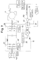
- the gas passes through a plug cock 2, a particulate filter 3, a solenoid isolating valve 4, a flexible connection 5, under and over pressure electronic sensors 6a and 6b and through an approved non-return valve 7.
- the inlet pipe passes through the wall of a compartment 8 where the gas passes through a check valve 9 and into the inlet of a compressor 10.
- the compressor 10 is a Lyscholm oil flooded screw type compressor which is driven by an electric motor 11 and an inverter device 12.
- the Lyscholm compressor 10 consists of two shafts or rotors (not shown) designated a female and male which interact like a long pitch multiple start thread squeezing the entrapped oil and gas axially from inlet to discharge. There is a near linear relationship between shaft speed and flow for discharge pressures within the normal operating range.
- the oil flood performs two basic tasks which are to lubricate and seal the rotors in the housing (not shown) and to absorb the heat of compression, making the compression polytropic and more efficient than an equivalent adiabatic process.
- a low discharge temperature for any given pressure ratio is thus realised and combined with the continuous presence of oil, corrosion is not a problem. Maintenance may indeed be zero even for an operating life in excess of 10 years.
- the outlet of the compressor 10 is connected to a separator tank 13 which separates oil from the oil and gas mixture and which helps to snub any small pressure pulsations in the discharge.
- the separator tank 13 is connected to the inlet of the compressor 10 through a filter 14 and a cooler 15 so that the separated oil is recirculated to the compressor 10. Furthermore, the separator tank 13 is connected to the pipe between the inlet of the compressor 10 and the check valve 9 through a relief valve 16. In this embodiment, when the pressure in the separator tank 13 becomes more than a predetermined pressure, the relief valve 16 is pneumatically opened and the gas is released to the inlet pipe and not to atmosphere.
- a level switch 19 for monitoring the oil level
- a pressure sensor 17 for monitoring the discharge (gas) pressure
- a thermocouple 18 for monitoring the discharge (gas) temperature. If an oil leak occurs and the lower oil level is detected by the level switch 19, or if the increase of the discharge (gas) temperature is detected by the thermocouple 18, these error signals are sent to a controller 31 which shuts down the system, thereby preventing the escape of gas.
- the separator tank 13 is connected to a coalescing filter 20 which removes small droplets of oil contained in the high pressure gas.
- the coalescing filter 20 is connected to the pipe between the inlet of the compressor 10 and the check valve 9 through a bleed hole 20a so as to recirculate the small amount of coalesced oil to the inlet of the compressor 10.
- the coalescing filter 20 is connected to a control valve 21 and the control valve 21 is connected to the pilot and primary burners of a combustion chamber 24 of a gas turbine engine 30 through cut-off valves 22 and 23.
- the control valve 21 is a proportional flow control valve and is controlled by a control signal of the controller 31 in response to an output signal of a comparator 32.
- the comparator 32 compares output power of the gas turbine engine 30 with a power reference 33 and sends the output signal to the controller 31.
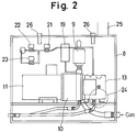
- the gaseous fuel control system is completely contained within the enclosed compartment 8.
- a ventilation fan (not shown) is connected and sealed to an opening 24 and air is circulated by the fan into the compartment 8 and exits through a second port 25. As the ventilation air circulates in the compartment some of it passes over gas detectors 26.
- the inverter device 12 is interposed between the electric induction motor 11 and the main electric source and includes a converter (rectifier or controlled rectifier) 37 which transforms AC into DC, an inverter 38 which transforms DC into AC, a compensator 35, such as a proportional, integral and derivative (PID) device, a second comparator 36, a power transducer 42, a control circuit 39 and a firing circuit 40.
- the current pressure signal of the pressure sensor 17 is compared in a first comparator 34 with a pressure reference 41, and an output signal of the first comparator 34 is sent to the compensator 35.
- the compensator 35 In response to that output signal, the compensator 35.
- the compensator 35 sends a compensating signal Iref to the second comparator 36.
- the compensating signal Iref is a current signal for obtaining a fuel pressure the same as the pressure reference 41.
- the compensating signal Iref is compared in the second comparator 36 with a current signal which is sent from the power transducer 42.
- the power transducer 42 may be disposed between the converter 37 and the inverter 38 or between the inverter 38 and the motor 11 (as illustrated) or between the mains electric source and the converter 37 and measures the current which is fed to the inverter 38.
- An output signal of the second comparator 36 is sent to the control circuit 39.
- the control circuit 39 which may be analogue or digital, determines what effective voltage and frequency must be synthesized by the inverter 38 in order to supply current to the motor 11 commensurate with present demand for speed and torque.
- the control circuit 39 determines the firing sequences necessary for the inverter 38 and sends these signals which may be TTL to the firing circuits 40 and 40'.
- the firing circuit 40' is designed to accept the control signals for the converter 37 which may be thyristors or any other type of appropriate semiconductor switching device. Electrical power from the mains electric source is thus inverted at d.c. voltage.
- the firing circuit 40 is designed to accept the control signals from the control circuits 39 and output the correct gate signals for the inverter 38 which may be transistors, mosfets, IGBTs or any other type of appropriate semiconductor switching device. Electrical power from the d.c. link is thus inverted at an appropriate voltage and a.c. frequency and can therefore modulate the motor speed as desired.
- the gas fuel control system operates firstly to produce the required fuel pressure to enable gas at an elevated pressure to enter the combustor for ignition, as follows.
- a pressure reference signal 41 which may be from an operator or from the gas turbine controller 31, is sent to the first comparator 34, the output of which is fed to the inverter device 12 to start up the motor 11 which drives the compressor 10 and immediately produces pressure in the separator tank 13 because the control valve 21 and the cut-off valves 22 and 23 are initially closed.
- the plug cock 2 and the solenoid isolating valve 4 are of course assumed to be opened for normal operation.
- the gas turbine start sequence can be started. If a pilot is used, the valve 23 will be opened by the controller 31. When this small flow flows, the gas compressor 10 must speed up a little to supply this small flow. When the pilot is lit, the primary valve 22 can be opened by the controller 31. The control valve 21 can be opened slowly thus gradually allowing more flow to gas turbine to accelerate it.
- control valve 21 can be omitted so that the speed of the motor 11 alone controls the supply of compressed hydrocarbon gas through the cut-off valves 22 and 23 to the gas turbine. If there is no control valve, the block valves can be opened before the gas compressor is energised. To start the engine the gas compressor can be accelerated under controlled conditions from the (gas turbine) controller 31.
- start sequence can be any that the owner, operator or manufacturer of the system wishes to employ.
- the (gas turbine) controller 31 of the embodiment of Figs. 1 to 5 generates two signals in response to output power. One is the required gas flow rate and therefore positions the control valve accordingly and the other is the required gas pressure which therefore is the gas compression system set point pressure.
- the controller 31 sends a signal to the control valve 21 which begins to close. A natural and temporary result of this is that the gas pressure rises slightly. The compressor 10 is therefore slowed down by the inverter device 12 until a new equilibrium is achieved.
- the controller 31 sends a signal to the control valve 21 which begins to open. A natural and temporary result is that the gas pressure falls slightly. The compressor 10 is therefore accelerated by the inverter device 12 until a new equilibrium is reached.
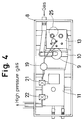
- Fig. 6 and Fig. 7 show a second embodiment of the invention in which the proportional control valve 21 of the first embodiment is eliminated.
- the same parts as those of Figs. 1 to 5 are identified by the same reference numerals.
- the speed of the motor 11 is controlled by the inverter device 12 directly in response to the output power of the gas turbine engine 30.
- the comparators 32 and 34 of the first embodiment are replaced in this second embodiment by a single comparator 32 which receives an input and feedback signal representing output power and the power reference signal 33.
- This embodiment operates as follows.
- the controller 31 sends its requirement for gas fuel flow directly to the inverter 12 of the gas compressor 10 through a changeover switch 43.
- the valves 4, 22 and 23 are opened.
- the compressor 10 is then started at low speed until the pilot is lit.
- the primary valve 23 can be opened and lit by the pilot.
- the controller requires more gas flow by accelerating a pilot, primary and main burners whilst other systems may only have a main burner.
- the start sequence can end and on actuation of the changeover switch 43 the engine 30 becomes controlled by the power feed back loop. If power is lower than the set point 33, the error signal produced tends to accelerate the gas compressor 30 whilst if the output power is higher than the set point 33 the error signal produced tends to slow down the compressor 10.
- the engine output power is modulated by the compressor speed. Since the other structures are the same as the first embodiment, the description is omitted.
- the fuel compressor speed is modulated by the motor inverter, compressed gas is supplied virtually on demand within the time it takes to accelerate the compressor shaft. There is no long term storage of dangerous compressed gas. Because the motor and inverter can be utilised as main control elements the control valve can be eliminated. By this method it is able to simplify the control of fuel flow to a gas turbine. Furthermore, since the connections are a few and the integrity of these connections is not threatened by any intense vibrations, it is able to improve the safety of the system.
Landscapes
- Engineering & Computer Science (AREA)
- Chemical & Material Sciences (AREA)
- Combustion & Propulsion (AREA)
- Mechanical Engineering (AREA)
- General Engineering & Computer Science (AREA)
- Control Of Eletrric Generators (AREA)
- Supercharger (AREA)
- Electrical Control Of Air Or Fuel Supplied To Internal-Combustion Engine (AREA)
- Output Control And Ontrol Of Special Type Engine (AREA)
Applications Claiming Priority (2)
| Application Number | Priority Date | Filing Date | Title |
|---|---|---|---|
| GB9408677 | 1994-04-30 | ||
| GB9408677A GB9408677D0 (en) | 1994-04-30 | 1994-04-30 | Gaseous fuel compression and control system for gas turbine engine |
Publications (2)
| Publication Number | Publication Date |
|---|---|
| EP0679800A2 true EP0679800A2 (de) | 1995-11-02 |
| EP0679800A3 EP0679800A3 (de) | 1998-04-01 |
Family
ID=10754433
Family Applications (1)
| Application Number | Title | Priority Date | Filing Date |
|---|---|---|---|
| EP95302857A Withdrawn EP0679800A3 (de) | 1994-04-30 | 1995-04-27 | Steuerungs- und Verdichtungssystem für die Zufuhr eines gasförmigen Brennstoffs für ein Gasturbine |
Country Status (4)
| Country | Link |
|---|---|
| US (1) | US5606853A (de) |
| EP (1) | EP0679800A3 (de) |
| JP (1) | JPH0861096A (de) |
| GB (1) | GB9408677D0 (de) |
Cited By (18)
| Publication number | Priority date | Publication date | Assignee | Title |
|---|---|---|---|---|
| EP0898362A1 (de) * | 1997-08-18 | 1999-02-24 | Asea Brown Boveri AG | Verfahren zur Versorgung einer Gasturbinenanlage |
| EP0837231A3 (de) * | 1996-10-16 | 1999-10-27 | Capstone Turbine Corporation | Verdichtungssystem eines gasförmigen Brennstoffs |
| EP0837224A3 (de) * | 1996-10-16 | 1999-11-03 | Capstone Turbine Corporation | Spiralverdichter oder Turbine mit permanent Magnetgenerator/Motor |
| WO2000009862A1 (en) * | 1998-08-14 | 2000-02-24 | Alliedsignal Inc. | Microturbine power generating system including variable-speed gas compressor |
| EP0901218A3 (de) * | 1997-09-08 | 2000-08-16 | Capstone Turbine Corporation | Regler für Turbolader/Motor |
| WO2002002920A1 (en) * | 2000-06-29 | 2002-01-10 | Capstone Turbine Corporation | System and method for gaseous fuel control for a turbogenerator/motor |
| US6487096B1 (en) | 1997-09-08 | 2002-11-26 | Capstone Turbine Corporation | Power controller |
| US6612112B2 (en) | 1998-12-08 | 2003-09-02 | Capstone Turbine Corporation | Transient turbine exhaust temperature control for a turbogenerator |
| WO2004053311A1 (en) * | 2002-12-10 | 2004-06-24 | Ingersoll-Rand Energy Systems Corporation | Hermetic motor and gas booster |
| US6784565B2 (en) | 1997-09-08 | 2004-08-31 | Capstone Turbine Corporation | Turbogenerator with electrical brake |
| US6787933B2 (en) | 2001-01-10 | 2004-09-07 | Capstone Turbine Corporation | Power generation system having transient ride-through/load-leveling capabilities |
| US6812586B2 (en) | 2001-01-30 | 2004-11-02 | Capstone Turbine Corporation | Distributed power system |
| EP1348870A3 (de) * | 2002-03-26 | 2004-11-17 | Copeland Corporation | Steuerungs- und Verdichtungssystem für die Zufuhr eines gasförmigen Brennstoffes |
| US6870279B2 (en) | 1998-01-05 | 2005-03-22 | Capstone Turbine Corporation | Method and system for control of turbogenerator power and temperature |
| EP2006492A1 (de) * | 2007-06-18 | 2008-12-24 | ABB Research Ltd | Anordnung, Verfahren und Anlage zur Kompression eines Gases oder einer Flüssigkeit |
| CN102979628A (zh) * | 2012-12-12 | 2013-03-20 | 天津市电力公司 | 一种实现燃气-蒸汽联合循环机组调频功能的方法 |
| EP3225817A1 (de) * | 2016-03-30 | 2017-10-04 | General Electric Company | Brennstoffverdichter mit variablem durchfluss einer gasturbine |
| IT202200016938A1 (it) * | 2022-08-08 | 2024-02-08 | Nuovo Pignone Tecnologie Srl | Integrazione booster di gas combustibile-turbina a gas per risparmio energetico e operatività ottimizzata |
Families Citing this family (33)
| Publication number | Priority date | Publication date | Assignee | Title |
|---|---|---|---|---|
| US5903116A (en) | 1997-09-08 | 1999-05-11 | Capstone Turbine Corporation | Turbogenerator/motor controller |
| US20020166324A1 (en) | 1998-04-02 | 2002-11-14 | Capstone Turbine Corporation | Integrated turbine power generation system having low pressure supplemental catalytic reactor |
| US6484490B1 (en) * | 2000-05-09 | 2002-11-26 | Ingersoll-Rand Energy Systems Corp. | Gas turbine system and method |
| US6622489B1 (en) | 2000-10-25 | 2003-09-23 | Hybrid Power Generation Systems, Llc | Integrated gas booster modulation control method |
| US6659729B2 (en) * | 2001-02-15 | 2003-12-09 | Mayekawa Mfg. Co., Ltd. | Screw compressor equipment for accommodating low compression ratio and pressure variation and the operation method thereof |
| US6881040B2 (en) * | 2001-02-15 | 2005-04-19 | Mayekawa Mfg. Co., Ltd. | Multi-stage screw compressor unit accommodating high suction pressure and pressure fluctuations and method of operation thereof |
| US7165947B2 (en) * | 2001-02-15 | 2007-01-23 | Mayekawa Mfg. Co., Ltd. | Screw compressor capable of manually adjusting both internal volume ratio and capacity and combined screw compressor unit accommodating variation in suction or discharge pressure |
| US6751941B2 (en) * | 2001-02-16 | 2004-06-22 | Capstone Turbine Corporation | Foil bearing rotary flow compressor with control valve |
| US6901735B2 (en) | 2001-08-01 | 2005-06-07 | Pipeline Controls, Inc. | Modular fuel conditioning system |
| JP2006169995A (ja) * | 2004-12-14 | 2006-06-29 | Takuma Co Ltd | マイクロガスタービン発電システム及び捕機電力供給方法 |
| DE102007044522B4 (de) * | 2007-09-18 | 2019-01-17 | Man Diesel & Turbo Se | Vorrichtung zur Regelung eines mit flüssigem und/oder gasförmigen Kraftstoff betreibbaren Verbrennungsmotors |
| USRE46725E1 (en) | 2009-09-11 | 2018-02-20 | Halliburton Energy Services, Inc. | Electric or natural gas fired small footprint fracturing fluid blending and pumping equipment |
| US8850818B2 (en) * | 2010-10-18 | 2014-10-07 | General Electric Company | Systems and methods for gas fuel delivery with hydrocarbon removal utilizing active pressure control and dew point analysis |
| US10232332B2 (en) | 2012-11-16 | 2019-03-19 | U.S. Well Services, Inc. | Independent control of auger and hopper assembly in electric blender system |
| US11449018B2 (en) | 2012-11-16 | 2022-09-20 | U.S. Well Services, LLC | System and method for parallel power and blackout protection for electric powered hydraulic fracturing |
| US9745840B2 (en) | 2012-11-16 | 2017-08-29 | Us Well Services Llc | Electric powered pump down |
| US9893500B2 (en) | 2012-11-16 | 2018-02-13 | U.S. Well Services, LLC | Switchgear load sharing for oil field equipment |
| US9995218B2 (en) | 2012-11-16 | 2018-06-12 | U.S. Well Services, LLC | Turbine chilling for oil field power generation |
| US10407990B2 (en) | 2012-11-16 | 2019-09-10 | U.S. Well Services, LLC | Slide out pump stand for hydraulic fracturing equipment |
| US11476781B2 (en) | 2012-11-16 | 2022-10-18 | U.S. Well Services, LLC | Wireline power supply during electric powered fracturing operations |
| CA2908276C (en) | 2014-10-14 | 2022-11-01 | Us Well Services Llc | Parallel power and blackout protection for electric hydraulic fracturing |
| US12078110B2 (en) | 2015-11-20 | 2024-09-03 | Us Well Services, Llc | System for gas compression on electric hydraulic fracturing fleets |
| US12027831B2 (en) | 2016-04-15 | 2024-07-02 | U.S. Well Services, LLC | Switchgear load sharing for oil field equipment |
| CA3206994A1 (en) | 2016-09-02 | 2018-03-08 | Halliburton Energy Services, Inc. | Hybrid drive systems for well stimulation operations |
| WO2019113147A1 (en) | 2017-12-05 | 2019-06-13 | U.S. Well Services, Inc. | Multi-plunger pumps and associated drive systems |
| US10648311B2 (en) | 2017-12-05 | 2020-05-12 | U.S. Well Services, LLC | High horsepower pumping configuration for an electric hydraulic fracturing system |
| WO2020056258A1 (en) | 2018-09-14 | 2020-03-19 | U.S. Well Services, LLC | Riser assist for wellsites |
| US11578577B2 (en) | 2019-03-20 | 2023-02-14 | U.S. Well Services, LLC | Oversized switchgear trailer for electric hydraulic fracturing |
| US11728709B2 (en) | 2019-05-13 | 2023-08-15 | U.S. Well Services, LLC | Encoderless vector control for VFD in hydraulic fracturing applications |
| AR119134A1 (es) | 2019-06-10 | 2021-11-24 | U S Well Services Llc | Calentador integrado de gas de combustión para equipos móviles de acondicionamiento de combustible |
| US11459863B2 (en) | 2019-10-03 | 2022-10-04 | U.S. Well Services, LLC | Electric powered hydraulic fracturing pump system with single electric powered multi-plunger fracturing pump |
| AU2023333309A1 (en) * | 2022-09-02 | 2025-03-20 | Nuovo Pignone Tecnologie - S.R.L. | System and method for treating wastewater from an oilfield well with co-production of power |
| US12540607B2 (en) | 2023-06-23 | 2026-02-03 | Halliburton Energy Services, Inc. | Hybrid drive and distributed power systems for well stimulation operations |
Family Cites Families (8)
| Publication number | Priority date | Publication date | Assignee | Title |
|---|---|---|---|---|
| US3693601A (en) * | 1971-01-06 | 1972-09-26 | Kenneth D Sauder | Rotary engine |
| US4815278A (en) * | 1987-10-14 | 1989-03-28 | Sundstrand Corporation | Electrically driven fuel pump for gas turbine engines |
| US4922710A (en) * | 1989-01-04 | 1990-05-08 | General Electric Company | Integrated boost compressor/gas turbine control |
| US4971522A (en) * | 1989-05-11 | 1990-11-20 | Butlin Duncan M | Control system and method for AC motor driven cyclic load |
| US5103629A (en) * | 1989-11-20 | 1992-04-14 | Westinghouse Electric Corp. | Gas turbine control system having optimized ignition air flow control |
| US5118258A (en) * | 1990-09-04 | 1992-06-02 | United Technologies Corporation | Dual pump fuel delivery system |
| JPH0610876A (ja) * | 1992-06-23 | 1994-01-21 | Hitachi Ltd | 給油式スクリュー圧縮機の容量制御方法 |
| BE1007135A6 (nl) * | 1993-06-16 | 1995-04-04 | Atlas Copco Airpower Nv | Regelinrichting met start- en stopinrichting voor schroefkompressoren, en daarbij gebruikte start- en stopinrichting. |
-
1994
- 1994-04-30 GB GB9408677A patent/GB9408677D0/en active Pending
-
1995
- 1995-04-27 EP EP95302857A patent/EP0679800A3/de not_active Withdrawn
- 1995-04-28 US US08/430,386 patent/US5606853A/en not_active Expired - Fee Related
- 1995-05-01 JP JP7128833A patent/JPH0861096A/ja active Pending
Cited By (23)
| Publication number | Priority date | Publication date | Assignee | Title |
|---|---|---|---|---|
| EP0837231A3 (de) * | 1996-10-16 | 1999-10-27 | Capstone Turbine Corporation | Verdichtungssystem eines gasförmigen Brennstoffs |
| EP0837224A3 (de) * | 1996-10-16 | 1999-11-03 | Capstone Turbine Corporation | Spiralverdichter oder Turbine mit permanent Magnetgenerator/Motor |
| EP0898362A1 (de) * | 1997-08-18 | 1999-02-24 | Asea Brown Boveri AG | Verfahren zur Versorgung einer Gasturbinenanlage |
| EP0901218A3 (de) * | 1997-09-08 | 2000-08-16 | Capstone Turbine Corporation | Regler für Turbolader/Motor |
| US6487096B1 (en) | 1997-09-08 | 2002-11-26 | Capstone Turbine Corporation | Power controller |
| US6784565B2 (en) | 1997-09-08 | 2004-08-31 | Capstone Turbine Corporation | Turbogenerator with electrical brake |
| US6870279B2 (en) | 1998-01-05 | 2005-03-22 | Capstone Turbine Corporation | Method and system for control of turbogenerator power and temperature |
| WO2000009862A1 (en) * | 1998-08-14 | 2000-02-24 | Alliedsignal Inc. | Microturbine power generating system including variable-speed gas compressor |
| US6612112B2 (en) | 1998-12-08 | 2003-09-02 | Capstone Turbine Corporation | Transient turbine exhaust temperature control for a turbogenerator |
| WO2002002920A1 (en) * | 2000-06-29 | 2002-01-10 | Capstone Turbine Corporation | System and method for gaseous fuel control for a turbogenerator/motor |
| US6787933B2 (en) | 2001-01-10 | 2004-09-07 | Capstone Turbine Corporation | Power generation system having transient ride-through/load-leveling capabilities |
| US6812586B2 (en) | 2001-01-30 | 2004-11-02 | Capstone Turbine Corporation | Distributed power system |
| EP1348870A3 (de) * | 2002-03-26 | 2004-11-17 | Copeland Corporation | Steuerungs- und Verdichtungssystem für die Zufuhr eines gasförmigen Brennstoffes |
| EP1698783A1 (de) * | 2002-03-26 | 2006-09-06 | Copeland Corporation | Steuerungs- und Verdichtungssystem für die Zufuhr eines gasförmigen Brennstoffes |
| WO2004053311A1 (en) * | 2002-12-10 | 2004-06-24 | Ingersoll-Rand Energy Systems Corporation | Hermetic motor and gas booster |
| EP2006492A1 (de) * | 2007-06-18 | 2008-12-24 | ABB Research Ltd | Anordnung, Verfahren und Anlage zur Kompression eines Gases oder einer Flüssigkeit |
| CN102979628A (zh) * | 2012-12-12 | 2013-03-20 | 天津市电力公司 | 一种实现燃气-蒸汽联合循环机组调频功能的方法 |
| CN102979628B (zh) * | 2012-12-12 | 2015-09-02 | 天津市电力公司 | 一种实现燃气-蒸汽联合循环机组调频功能的方法 |
| EP3225817A1 (de) * | 2016-03-30 | 2017-10-04 | General Electric Company | Brennstoffverdichter mit variablem durchfluss einer gasturbine |
| CN107269401A (zh) * | 2016-03-30 | 2017-10-20 | 通用电气公司 | 燃气轮机的可变流量压缩机 |
| US10036325B2 (en) | 2016-03-30 | 2018-07-31 | General Electric Company | Variable flow compressor of a gas turbine |
| IT202200016938A1 (it) * | 2022-08-08 | 2024-02-08 | Nuovo Pignone Tecnologie Srl | Integrazione booster di gas combustibile-turbina a gas per risparmio energetico e operatività ottimizzata |
| WO2024032933A1 (en) * | 2022-08-08 | 2024-02-15 | Nuovo Pignone Tecnologie - S.R.L. | Fuel gas booster-gas turbine integration for energy saving & optimized operability |
Also Published As
| Publication number | Publication date |
|---|---|
| US5606853A (en) | 1997-03-04 |
| GB9408677D0 (en) | 1994-06-22 |
| EP0679800A3 (de) | 1998-04-01 |
| JPH0861096A (ja) | 1996-03-05 |
Similar Documents
| Publication | Publication Date | Title |
|---|---|---|
| US5606853A (en) | Gaseous fuel compression and control system for gas turbine engine | |
| US6484490B1 (en) | Gas turbine system and method | |
| JP3658415B2 (ja) | ガスタービン装置 | |
| EP0398436B1 (de) | Verdichterregelsystem zur Verbesserung der Mindestfördermenge und zur Verminderung des Pumpens | |
| US5355854A (en) | Supplemental gaseous fuel system for a diesel engine | |
| EP0377292B1 (de) | Regelsystem für einen Brenngasverdichter und eine durch diesen versorgte Gasturbine | |
| KR890004397B1 (ko) | 냉각장치의 전기모우터식 압축기를 보호하는 제어장치와 그 방법 | |
| EP0158582A2 (de) | Zweifach-Absaugung zum Schützen eines Verdichters in einem Kältesystem | |
| US7472542B2 (en) | Gas-turbine power generating installation and method of operating the same | |
| CN103967623B (zh) | 燃气涡轮欠频响应改进系统和方法 | |
| AU2007347705B2 (en) | Anti-bogdown control system for turbine/compressor systems | |
| JPH11294342A (ja) | コンプレッサ装置と、それに使用する制御装置 | |
| JPH06317319A (ja) | 暖房装置のガス自動燃焼制御装置用の制御装置とその使用方法 | |
| US4468171A (en) | Method of controlling air flow rate of fan | |
| JP4319481B2 (ja) | 希薄燃焼ガスエンジンの燃料ガス供給、給気装置 | |
| EP0666452A1 (de) | Fehlererkennung eines Fühlers | |
| US4976588A (en) | Compressor control system to improve turndown and reduce incidents of surging | |
| JP2554053B2 (ja) | 機関の燃料制御装置 | |
| US6330805B1 (en) | Method of operating a refrigerating unit with a refrigerant fluid circuit | |
| US4019323A (en) | Controller for turbocharger system for internal combustion engines | |
| EP0562144A1 (de) | Verfahren zur Regelung von Kesseldruck | |
| US4192489A (en) | Control system for an installation utilizing pressure energy of outgoing blast-furnace gas | |
| JPH0248757B2 (de) | ||
| EP1427941B1 (de) | Motorgetriebener verdichter | |
| JP3110976B2 (ja) | ガス昇圧装置の制御方法及び制御装置 |
Legal Events
| Date | Code | Title | Description |
|---|---|---|---|
| PUAI | Public reference made under article 153(3) epc to a published international application that has entered the european phase |
Free format text: ORIGINAL CODE: 0009012 |
|
| AK | Designated contracting states |
Kind code of ref document: A2 Designated state(s): DE GB SE |
|
| 17P | Request for examination filed |
Effective date: 19951113 |
|
| PUAL | Search report despatched |
Free format text: ORIGINAL CODE: 0009013 |
|
| AK | Designated contracting states |
Kind code of ref document: A3 Designated state(s): DE GB SE |
|
| 17Q | First examination report despatched |
Effective date: 20000126 |
|
| STAA | Information on the status of an ep patent application or granted ep patent |
Free format text: STATUS: THE APPLICATION HAS BEEN WITHDRAWN |
|
| 18W | Application withdrawn |
Withdrawal date: 20000703 |