EP0679830A2 - Rohrkreuzungsfitting - Google Patents
Rohrkreuzungsfitting Download PDFInfo
- Publication number
- EP0679830A2 EP0679830A2 EP95105810A EP95105810A EP0679830A2 EP 0679830 A2 EP0679830 A2 EP 0679830A2 EP 95105810 A EP95105810 A EP 95105810A EP 95105810 A EP95105810 A EP 95105810A EP 0679830 A2 EP0679830 A2 EP 0679830A2
- Authority
- EP
- European Patent Office
- Prior art keywords
- section
- cross
- flow
- flow channel
- connection
- Prior art date
- Legal status (The legal status is an assumption and is not a legal conclusion. Google has not performed a legal analysis and makes no representation as to the accuracy of the status listed.)
- Granted
Links
Images

Classifications
-
- F—MECHANICAL ENGINEERING; LIGHTING; HEATING; WEAPONS; BLASTING
- F24—HEATING; RANGES; VENTILATING
- F24D—DOMESTIC- OR SPACE-HEATING SYSTEMS, e.g. CENTRAL HEATING SYSTEMS; DOMESTIC HOT-WATER SUPPLY SYSTEMS; ELEMENTS OR COMPONENTS THEREFOR
- F24D19/00—Details
- F24D19/0002—Means for connecting central heating radiators to circulation pipes
- F24D19/0009—In a two pipe system
-
- F—MECHANICAL ENGINEERING; LIGHTING; HEATING; WEAPONS; BLASTING
- F16—ENGINEERING ELEMENTS AND UNITS; GENERAL MEASURES FOR PRODUCING AND MAINTAINING EFFECTIVE FUNCTIONING OF MACHINES OR INSTALLATIONS; THERMAL INSULATION IN GENERAL
- F16L—PIPES; JOINTS OR FITTINGS FOR PIPES; SUPPORTS FOR PIPES, CABLES OR PROTECTIVE TUBING; MEANS FOR THERMAL INSULATION IN GENERAL
- F16L41/00—Branching pipes; Joining pipes to walls
- F16L41/02—Branch units, e.g. made in one piece, welded, riveted
- F16L41/03—Branch units, e.g. made in one piece, welded, riveted comprising junction pieces for four or more pipe members
Definitions
- the invention relates to a pipe crossing fitting, consisting of a base body with two separate flow channels, which are each assigned circular connection cross-sections for pipes on the end faces, in particular for the connection of radiators to pipes, which are mounted behind commercially available baseboards.
- a typical problem area of such installations is the connection of radiators to pipelines which are attached to the wall directly above the floor and can be covered with commercially available baseboards.
- the baseboards are assigned fastening clamps that are adapted to the spacing of the pipes. Because of the limited installation space, special assemblies are necessary in order to be able to connect the radiator in the space between the inner profile of the baseboard and the floor and wall.
- a radiator connection is already known for this purpose, in which a separate assembly is used for the connection of each pipeline.
- a pipe bend branching off the lower pipe is guided past the upper pipe in a recess in the masonry (state of the art according to the brochure "We bring heat into the room", issue 93/94 of the company HZ Hans Weitzel GmbH, Ingelheim).
- a major disadvantage of this technical solution is that the branching of the lower pipe can only be carried out if there is sufficient free space behind the upper pipe.
- the use of "HZ radiator connections” therefore mainly requires additional work steps for the installer, for example a recess in the masonry behind the pipe. Such additional work on the masonry can be avoided by installing the pipe crossing piece according to DE 27 23 556.
- the invention relates to a pipe crossing fitting, which enables the design of pipe crossings in the space between the inner profile of skirting boards and floor and wall without any changes to the masonry and without changes in cross-section in the flow channel of the pipes.
- the first flow channel in the base body merges between the connection cross sections into a flow section with a non-circular cross section, which is offset in height from the central longitudinal axis of the connection cross sections, the outer boundary wall of which corresponds to the associated longitudinal outer wall of the base body.
- the second flow channel is configured in the base body between the connection cross-sections without any change in direction or cross-section and in the area of the vertically offset section of the first flow channel has a branch, preferably perpendicular to its longitudinal axis, between the inner boundary wall of the vertically offset section of the first flow channel and the this opposite longitudinal outer wall of the base body is designed and merges into a circular pipe connection piece.
- the flow cross section of the vertically offset flow section has the same surface area as the connection cross section of the assigned first flow channel and the vertical branch has the same surface area as the assigned pipe connection piece.
- the first flow channel has a pipe connection piece, which is preferably configured at right angles to the central longitudinal axis of the associated connection cross sections.
- Particularly advantageous flow conditions in the pipe crossing fitting are achieved if the flow section of the first flow channel which is offset in height is one has approximately trapezoidal cross-sectional area.
- the distance between the connection cross sections of the first and second flow channels corresponds to the gauge of commercially available fastening clamps for baseboards.
- the assembly effort is further advantageously reduced if the distance between the pipe connection pieces of the first and second flow channels corresponds to the inside dimension of valve radiators.
- the use of the pipe crossing fitting according to the invention results in considerable time and cost savings compared to the known pipe crossings when installing radiator connections. Easy and quick installation is achieved without any intervention in the insulation of the pipes or the screed of the installation wall.
- the structural design of the base body causes only minor changes in direction and flow resistance.
- the proposed pipe crossing fitting is particularly suitable for a combination with commercially available baseboards, in addition to the technical advantages mentioned, an optically perfect vertical exit of the pipe connections from the baseboard is achieved.
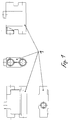
- the pipe crossing fitting shown in the drawing consists of a base body 1, in which two separate flow channels 2 and 3 are configured.
- the flow channels 2, 3 have on the end faces of the base body 1 each have circular connection cross-sections.
- the connection cross-sections are used to hold pipes, which are not shown in the drawing.
- the first flow channel 2 merges into a flow section 4 in the base body 1 in the area between the connection cross sections.
- the flow section 4 is arranged offset in height from the central longitudinal axis of the connection cross sections of the first flow channel 2 and has a non-circular cross section. As shown in FIG. 3, this flow section 4 can, for example, have an approximately trapezoidal cross-sectional area. It is essential here that the flow section 4 has the same surface area as the connection cross section of the first flow channel 2.
- the outer boundary wall of the flow section 4 corresponds to the assigned longitudinal outer wall 5 of the base body 1.
- the second flow channel 3 runs within the base body 1 between its connection cross sections without changing the direction or cross section.
- a branch 6 in the area of the flow section 4, which preferably runs perpendicular to the longitudinal axis of the flow channel 3.
- This branch 6 is configured between the inner boundary wall of the flow section 4 and the longitudinal outer wall 7 of the base body 1 opposite this.
- the branch 6 merges into a circular pipe connection piece 8, the branch 6 and the pipe connection piece 8 having the same area.
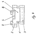
- the pipe crossing fitting can also have a pipe connection stub 9 on the first flow channel 2, which is preferably configured at right angles to the central longitudinal axis of the connection cross sections of the first flow channel 2.
- connection cross sections of the first and second flow channels 2 and 3 suitably corresponds to the gauge of commercially available fastening clamps for baseboards. It is also advantageous if the distance between the pipe connecting pieces 9 and 8 of the first and second flow channels 2 and 3 corresponds to the inside dimension of valve radiators.
- the flow channel 2 is connected to the flow line and the flow channel 3 is connected to the return line, these pipelines being guided directly on the wall and including the pipe crossing fittings can be covered with commercially available baseboards.
- the radiator is connected via pipe connection pieces 9 and 8.
Landscapes
- Engineering & Computer Science (AREA)
- General Engineering & Computer Science (AREA)
- Mechanical Engineering (AREA)
- Physics & Mathematics (AREA)
- Thermal Sciences (AREA)
- Chemical & Material Sciences (AREA)
- Combustion & Propulsion (AREA)
- Steam Or Hot-Water Central Heating Systems (AREA)
- Mutual Connection Of Rods And Tubes (AREA)
- Sewage (AREA)
- Superconductors And Manufacturing Methods Therefor (AREA)
- Domestic Hot-Water Supply Systems And Details Of Heating Systems (AREA)
Abstract
Description
- Die Erfindung betrifft einen Rohrkreuzungsfitting, bestehend aus einem Grundkörper mit zwei separaten Strömungskanälen, denen stirnseitig jeweils kreisförmige Anschlußquerschnitte für Rohrleitungen zugeordnet sind, insbesondere für den Anschluß von Heizkörpern an Rohrleitungen, welche hinter handelsüblichen Fußleisten montiert sind.
- Für zahlreiche technische Einsatzgebiete ist die Ausbildung von Kreuzungsstellen an Rohrinstallationen notwendig. Eine typische Problemstelle solcher Installationen ist der Anschluß von Heizkörpern an Rohrleitungen, die unmittelbar über dem Fußboden an der Wand befestigt sind und mit handelsüblichen Fußleisten abgedeckt werden können. Den Fußleisten sind bei dieser Installationsvariante Befestigungsschellen zugeordnet, die dem Abstand der Rohrleitungen angepaßt sind. Wegen des begrenzten Bauraumes sind spezielle Baugruppen notwendig, um den Heizkörperanschluß im Freiraum zwischen dem Innenprofil der Fußbodenleiste sowie Fußboden und Wand ausführen zu können.
- Für diesen Einsatzzweck ist bereits ein Heizkörperanschluß bekannt, bei dem für den Anschluß jeder Rohrleitung eine separate Baugruppe verwendet wird. Ein vom unteren Rohr abzweigender Rohrbogen wird hierbei in einer Aussparung des Mauerwerks am oberen Rohr vorbeigeführt (Stand der Technik gemäß Prospekt "Wir bringen Wärme in den Raum" Ausgabe 93/94 der Firma HZ Hans Weitzel GmbH, Ingelheim). Ein wesentlicher Nachteil dieser technischen Lösung besteht jedoch darin, daß ein Vorbeiführen der Abzweigung des unteren Rohres nur möglich ist, sofern hinter dem oberen Rohr genügend freier Bauraum vorhanden Ist. Die Anwendung von "HZ - Heizkörperanschlüssen" erfordert demzufolge überwiegend zusätzliche Arbeitsschritte für den Installateur, beispielsweise eine Aussparung des Mauerwerks hinter dem Rohr. Durch Installation des Rohrkreuzungsstückes gemäß DE 27 23 556 können solche zusätzlichen Arbeiten am Mauerwerk vermieden werden. Alle notwendigen Strömungskanäle für Vorlauf und Rücklauf sowie deren Abgänge sind bei dieser technischen Lösung innerhalb eines Grundkörpers angeordnet. Am Grundkörper sind stirnseitig jeweils kreisförmige Anschlußquerschnitte für die anzuschließenden Rohrleitungen ausgestaltet. Das Rohrkreuzungsstuck kann aufgrund seiner Abmessungen ohne Probleme im vorhandenen Bauraum handelsüblicher Fußleisten montiert werden. Allerdings bedingt diese konstruktive Gestaltung des Grundkörpers in den Strömungskanalen eine Querschnittsverminderung gegenüber den jeweiligen Anschlußquerschnitten der Rohrleitungen, so daß strömungstechnische Nachteile entstehen.
- Gegenstand der Erfindung ist ein Rohrkreuzungsfitting, der die Ausgestaltung von Rohrkreuzungen im Bauraum zwischen dem Innenprofil von Fußbodenleisten sowie Fußboden und Wand ohne jegliche Veränderungen am Mauerwerk sowie ohne Querschnittsveränderungen im Strömungskanal der Rohrleitungen ermöglicht.
- Erfindungsgemäß wird dies erreicht, indem der erste Strömungskanal im Grundkörper zwischen den Anschlußquerschnitten in einen, zur Mittellängsachse der Anschlußquerschnitte höhenversetzt angeordneten Strömungsabschnitt mit nichtkreisförmigem Querschnitt übergeht, dessen außenliegende Begrenzungswand der zugeordneten längsseitigen Außenwand des Grundkörpers entspricht. Der zweite Strömungskanal ist im Grundkörper zwischen den Anschlußquerschnitten jeweils ohne Richtungs- oder Querschnittsänderung ausgestaltet und weist im Bereich des höhenversetzt angeordneten Abschnittes des ersten Strömungskanals eine zu seiner Längsachse vorzugsweise senkrechte Abzweigung auf, die zwischen der innenliegenden Begrenzungswand des höhenversetzt angeordneten Abschnittes des ersten Strömungskanals und der diesem entgegengesetzten längsseitigen Außenwand des Grundkörpers ausgestaltet ist und in einen kreisförmigen Rohranschlußstutzen übergeht. Der Strömungsquerschnitt des höhenversetzt angeordneten Strömungsabschnittes hat denselben Flächeninhalt wie der Anschlußquerschnitt des zugeordneten ersten Strömungskanals und die senkrechte Abzweigung hat denselben Flächeninhalt wie der zugeordnete Rohranschlußstutzen.
- In Ausgestaltung der Erfindung weist der erste Strömungskanal einen Rohranschlußstutzen auf, der vorzugsweise rechtwinklig zur Mittellängsachse der zugeordneten Anschlußquerschnitte ausgestaltet ist. Besonders vorteilhafte Strömungsverhältnisse im Rohrkreuzungsfitting werden erreicht, sofern der höhenversetzt angeordnete Strömungsabschnitt des ersten Strömungskanals eine annähernd trapezförmige Querschnittsfläche aufweist. Zur Gewährleistung einer einfachen und schnellen Montage wird vorgeschlagen, daß der Abstand zwischen den Anschlußquerschnitten des ersten und zweiten Strömungskanals dem Stichmaß handelsüblicher Befestigungsschellen für Fußleisten entspricht. Der Montageaufwand wird weiterhin vorteilhaft vermindert, wenn der Abstand zwischen den Rohranschlußstutzen des ersten und zweiten Strömungskanals dem Stichmaß von Ventilheizkörpern entspricht.
- Die Anwendung des erfindungsgemäßen Rohrkreuzungsfittings ergibt bei der Installation von Heizkörperanschlüssen erhebliche Zeit- und Kosteneinsparungen gegenüber den bekannten Rohrkreuzungen. Es wird eine problemlose und schnelle Montage erreicht, ohne jegliche Eingriffe in die Isolation der Rohrleitungen oder den Estrich der Installationswand. Die konstruktive Ausgestaltung des Grundkörpers bewirkt lediglich geringfügige Richtungsänderungen und Strömungswiderstände. Der vorgeschlagene Rohrkreuzungsfitting ist besonders für eine Kombination mit handelsüblichen Fußleisten geeignet, wobei neben den erwähnten technischen Vorteilen auch ein optisch einwandfreier vertikaler Austritt der Rohranschlüsse aus der Fußleiste erzielt wird.
- Ein Ausführungsbeispiel der Erfindung ist in der Zeichnung dargestellt und wird nachfolgend beschrieben. Es zeigen
- Fig.1
- den Rohrkreuzungsfitting in Vorderansicht, Seitenansicht, Hinteransicht mit teilweise aufgebrochenem Grundkörper und in Draufsicht
- Fig.2
- den Rohrkreuzungsfitting im Längsschnitt
- Fig.3
- den Rohrkreuzungsfitting im Querschnitt
- Fig.4
- eine weitere Ausgestaltung des Rohrkreuzungsfittings im Längsschnitt.
- Der in der Zeichnung dargestellte Rohrkreuzungsfitting besteht aus einem Grundkörper 1, in dem zwei separate Strömungskanäle 2 und 3 ausgestaltet sind. Die Strömungskanäle 2;3 weisen an den Stirnseiten des Grundkörpers 1 jeweils kreisförmige Anschlußquerschnitte auf. Die Anschlußquerschnitte dienen zur Aufnahme von Rohrleitungen, die in der Zeichnung nicht näher dargestellt sind. Der erste Strömungskanal 2 geht im Grundkörper 1 im Bereich zwischen den Anschlußquerschnitten in einen Strömungsabschnitt 4 über. Der Strömungsabschnitt 4 ist zur Mittellängsachse der Anschlußquerschnitte des ersten Strömungskanals 2 höhenversetzt angeordnet und weist einen nichtkreisförmigen Querschnitt auf. Dieser Strömungsabschnitt 4 kann, wie in Fig.3 dargestellt, zum Beispiel eine annähernd trapezförmige Querschnittsfläche aufweisen. Wesentlich ist hierbei, daß der Strömungsabschnitt 4 denselben Flächeninhalt wie der Anschlußquerschnitt des ersten Strömungskanals 2 aufweist. Die außenliegende Begrenzungswand des Strömungsabschnittes 4 entspricht der zugeordneten längsseitigen Außenwand 5 des Grundkörpers 1.
- Der zweite Strömungskanal 3 verläuft innerhalb des Grundkörpers 1 zwischen seinen Anschlußquerschnitten ohne Richtungs- oder Querschnittsänderung. Am zweiten Strömungskanal 3 ist im Bereich des Strömungsabschnittes 4 eine Abzweigung 6 vorhanden, die vorzugsweise senkrecht zur Längsachse des Strömungskanals 3 verläuft. Diese Abzweigung 6 ist zwischen der innenliegenden Begrenzungswand des Strömungsabschnittes 4 und der diesem entgegengesetzten längsseitigen Außenwand 7 des Grundkörpers 1 ausgestaltet. Die Abzweigung 6 geht in einen kreisförmigen Rohranschlußstutzen 8 über, wobei die Abzweigung 6 und der Rohranschlußstutzen 8 denselben Flächeninhalt aufweisen.
- Der Rohrkreuzungsfitting kann, wie in Fig.4 dargestellt, auch am ersten Strömungskanal 2 einen Rohranschlußstutzen 9 aufweisen, der vorzugsweise rechtwinklig zur Mittellängsachse der Anschlußquerschnitte des ersten Strömungskanals 2 ausgestaltet ist.
- Der Abstand zwischen den Anschlußquerschnitten des ersten und zweiten Strömungskanals 2 und 3 entspricht zweckmäßig dem Stichmaß handelsüblicher Befestigungsschellen für Fußleisten. Weiterhin ist es vorteilhaft, wenn der Abstand zwischen den Rohranschlußstutzen 9 und 8 des ersten und zweiten Strömungskanals 2 und 3 dem Stichmaß von Ventilheizkörpern entspricht.
- Bei Anwendung des Rohrkreuzungsfittings für Heizinstallationen wird z.B. der Strömungskanal 2 mit der Vorlaufleitung und der Strömungskanal 3 mit der Rücklaufleitung verbunden, wobei diese Rohrleitungen unmittelbar an der Wand geführt sind und einschließlich des Rohrkreuzungsfittings mit handelsüblichen Fußleisten abgedeckt werden können. Der Anschluß des Heizkörpers erfolgt über die Rohranschlußstutzen 9 und 8.
Claims (5)
- Rohrkreuzungsfitting, bestehend aus einem Grundkörper mit zwei separaten Strömungskanälen, denen stirnseitig jeweils kreisförmige Anschlußquerschnitte für Rohrleitungen zugeordnet sind, insbesondere für den Anschluß von Heizkörpern an Rohrleitungen, welche hinter handelsüblichen Fußleisten montiert sind,
gekennzeichnet dadurch,
daß der erste Strömungskanal (2) im Grundkörper (1) zwischen den Anschlußquerschnitten in einen, zur Mittellängsachse der Anschlußquerschnitte höhenversetzt angeordneten Strömungsabschnitt (4) mit nichtkreisförmigem Querschnitt übergeht, dessen außenliegende Begrenzungswand der zugeordneten längsseitigen Außenwand (5) des Grundkörpers (1) entspricht und der zweite Strömungskanal (3) im Grundkörper (1) zwischen den Anschlußquerschnitten jeweils ohne Richtungs- oder Querschnittsänderung ausgestaltet ist, wobei dieser zweite Strömungskanal (3) im Bereich des höhenversetzt angeordneten Abschnittes (4) des ersten Strömungskanals (2) eine zu seiner Längsachse vorzugsweise senkrechte Abzweigung (6) aufweist, die zwischen der innenliegenden Begrenzungswand des höhenversetzt angeordneten Abschnittes (4) des ersten Strömungskanals (2) und der diesem entgegengesetzten längsseitigen Außenwand (7) des Grundkörpers (1) ausgestaltet ist und in einen kreisförmigen Rohranschlußstutzen (8) übergeht und wobei der Strömungsquerschnitt des höhenversetzt angeordneten Strömungsabschnittes (4) denselben Flächeninhalt wie der Anschlußquerschnitt des zugeordneten ersten Strömungskanals (2) und die senkrechte Abzweigung (6) denselben Flächeninhalt wie der zugeordnete Rohranschlußstutzen (8) aufweist. - Rohrkreuzungsfitting nach Anspruch 1,
gekennzeichnet dadurch,
daß der erste Strömungskanal (2) einen Rohranschlußstutzen (9) aufweist, der vorzugsweise rechtwinklig zur Mittellängsachse der zugeordneten Anschlußquerschnitte ausgestaltet ist. - Rohrkreuzungsfitting nach Anspruch 1,
gekennzeichnet dadurch,
daß der höhenversetzt angeordnete Strömungsabschnitt (4) des ersten Strömungskanals (2) eine annähernd trapezförmige Querschnittsfläche aufweist. - Rohrkreuzungsfitting nach Anspruch 1,
gekennzeichnet dadurch,
daß der Abstand zwischen den Anschlußquerschnitten des ersten und zweiten Strömungskanals (2;3) dem Stichmaß handelsüblicher Befestigungsschellen für Fußleisten entspricht. - Rohrkreuzungsfitting nach Anspruch 1 und 2,
gekennzeichnet dadurch,
daß der Abstand zwischen den Rohranschlußstutzen (9;8) des ersten und zweiten Strömungskanals (2;3) dem Stichmaß von Ventilheizkörpern entspricht.
Applications Claiming Priority (2)
| Application Number | Priority Date | Filing Date | Title |
|---|---|---|---|
| DE9406862U | 1994-04-25 | ||
| DE9406862U DE9406862U1 (de) | 1994-04-25 | 1994-04-25 | Rohrkreuzungsfitting |
Publications (3)
| Publication Number | Publication Date |
|---|---|
| EP0679830A2 true EP0679830A2 (de) | 1995-11-02 |
| EP0679830A3 EP0679830A3 (de) | 1996-07-17 |
| EP0679830B1 EP0679830B1 (de) | 2000-06-14 |
Family
ID=6907812
Family Applications (1)
| Application Number | Title | Priority Date | Filing Date |
|---|---|---|---|
| EP95105810A Expired - Lifetime EP0679830B1 (de) | 1994-04-25 | 1995-04-19 | Rohrkreuzungsfitting |
Country Status (4)
| Country | Link |
|---|---|
| EP (1) | EP0679830B1 (de) |
| AT (1) | ATE193934T1 (de) |
| CZ (1) | CZ3406U1 (de) |
| DE (1) | DE9406862U1 (de) |
Cited By (1)
| Publication number | Priority date | Publication date | Assignee | Title |
|---|---|---|---|---|
| DE19815437C1 (de) * | 1998-04-07 | 1999-07-22 | Lindner Armaturen Gmbh | Heizkörperanschlußeinheit |
Families Citing this family (2)
| Publication number | Priority date | Publication date | Assignee | Title |
|---|---|---|---|---|
| DE4427590C1 (de) * | 1994-08-04 | 1996-02-29 | Gerhard Rosenberg | Anschlußsystem für sanitäre Einrichtungen |
| DE19717251C1 (de) * | 1997-04-24 | 1998-05-14 | Beul Aba Gmbh | Rohrkreuzungsfitting |
Family Cites Families (14)
| Publication number | Priority date | Publication date | Assignee | Title |
|---|---|---|---|---|
| AT222853B (de) | 1960-02-03 | 1962-08-10 | Rolf Jacobsen | Verbindungsstück für Rohre |
| GB912907A (en) | 1960-02-03 | 1962-12-12 | Jacobsen Rolf | Improvements in junction piece for pipes |
| GB1324984A (en) | 1969-07-04 | 1973-07-25 | Sealed Motor Const Co Ltd | Manifolds |
| FR2227489B3 (de) * | 1973-04-27 | 1976-10-15 | Bosch Gmbh Robert | |
| DE2723556A1 (de) | 1977-05-25 | 1978-11-30 | Meibes | Rohrkreuzungsstueck fuer fluessige und gasfoermige medien |
| DE3629076A1 (de) | 1986-08-27 | 1988-03-10 | Jost Johannes Dipl Ing Fh | Rohrformstueck fuer rohrleitungen, insbesondere fuer heizkoerperanschlussleitungen |
| AT390661B (de) | 1987-12-02 | 1990-06-11 | Thermopanel Ges M B H | Anschlusseinrichtung fuer das anschliessen von heizkoerpern |
| WO1989007224A1 (en) | 1988-02-05 | 1989-08-10 | Curt Hammarstedt | A heat installation for premises with water as a heat transmitting medium |
| DE9105038U1 (de) * | 1991-01-28 | 1991-10-31 | Karl Rafeld KG Spritzgußwerk, Elektronik und Formenbau, 8954 Biessenhofen | Übergangsstück zur Heizkörperanbindung in Räumen |
| DE9100953U1 (de) | 1991-01-28 | 1991-04-18 | Karl Rafeld KG Spritzgußwerk, Elektronik und Formenbau, 8954 Biessenhofen | Übergangsstück zur Heizkörperanbindung in Räumen |
| DE4305694A1 (de) | 1993-02-25 | 1994-09-01 | Dumser Metallbau Gmbh | Verteileraggregat für mit einem strömungsfähigen Wärmeträgermedium arbeitende Heiz- oder Kühlanlagen |
| DE9317935U1 (de) | 1993-02-25 | 1994-01-13 | Dumser Metallbau GmbH, 76829 Landau | Verteileraggregat für mit einem strömungsfähigen Wärmeträgermedium arbeitende Heiz- oder Kühlanlagen |
| DE19609217A1 (de) | 1996-03-09 | 1997-09-11 | Stoof Klaus Peter | Rohrleitungssystem |
| DE29700661U1 (de) | 1997-01-16 | 1997-02-27 | ABA Beul GmbH, 57439 Attendorn | Anschlußeinrichtung für Heizungsrohre o.dgl. |
-
1994
- 1994-04-25 DE DE9406862U patent/DE9406862U1/de not_active Expired - Lifetime
-
1995
- 1995-04-12 CZ CZ19953811U patent/CZ3406U1/cs unknown
- 1995-04-19 EP EP95105810A patent/EP0679830B1/de not_active Expired - Lifetime
- 1995-04-19 AT AT95105810T patent/ATE193934T1/de not_active IP Right Cessation
Cited By (1)
| Publication number | Priority date | Publication date | Assignee | Title |
|---|---|---|---|---|
| DE19815437C1 (de) * | 1998-04-07 | 1999-07-22 | Lindner Armaturen Gmbh | Heizkörperanschlußeinheit |
Also Published As
| Publication number | Publication date |
|---|---|
| DE9406862U1 (de) | 1994-07-14 |
| CZ3406U1 (cs) | 1995-05-30 |
| EP0679830B1 (de) | 2000-06-14 |
| ATE193934T1 (de) | 2000-06-15 |
| EP0679830A3 (de) | 1996-07-17 |
Similar Documents
| Publication | Publication Date | Title |
|---|---|---|
| EP0579270A1 (de) | Sanitär- und Heizungsrohrsystem, vollständig oder überwiegend bestehend aus Kunststoff | |
| DE19728224C1 (de) | Kabelverlegesystem | |
| EP3690155A1 (de) | Armaturenanordnung | |
| EP0679830B1 (de) | Rohrkreuzungsfitting | |
| DE3315786A1 (de) | Anschlussdose fuer insbesondere eine wasserleitungsanlage | |
| DE3878471T2 (de) | Rohr zur innenbeschichtung von unter druck stehenden wasserleitungen. | |
| WO2014140714A1 (de) | Rohrverbindungsstück | |
| DE10219196A1 (de) | Anschlussarmatur | |
| CH495524A (de) | Klosett mit Abgangsleitung | |
| DE9201997U1 (de) | Biegsames Rohr oder Rohrformstück | |
| DE202006006746U1 (de) | Verbindungseinheit mit Schelle | |
| DE10009137C1 (de) | Heizkörperanschluß mit einem Rohranschluß für den Vorlauf und einem Rohranschluß für den Rücklauf des Heizmediums | |
| DE2911274C3 (de) | Doppelrohrkreuzung | |
| DE3832399A1 (de) | Rohrhalter und verfahren zur rohrmontage mittels eines rohrhalters | |
| AT505083B1 (de) | Halterung für rohre | |
| EP2023058B1 (de) | Anschlussstück für einen eine Innenzirkulationsleitung aufweisenden Flüssigkeitskreislauf einer Brauchwasser- oder Heizwasserversorgungsanlage, Leitungsanordnung mit einem solchen Anschlussstück und Verfahren zum Montieren einer solchen Leitungsanordnung | |
| DE20014221U1 (de) | Rohrkreuzungsfitting | |
| EP2060855A1 (de) | Anschlussstück für ein schlauchförmiges Innenzirkulationsrohr, Wasserzirkulationsleitung mit einem solchen Abschlussstück und Verfahren zum Montieren einer solchen Wasserzirkulationsleitung | |
| DE9308976U1 (de) | Haltevorrichtung für Heizungsrohre | |
| DE3629076A1 (de) | Rohrformstueck fuer rohrleitungen, insbesondere fuer heizkoerperanschlussleitungen | |
| DE29818512U1 (de) | Preßfitting | |
| DE4239262A1 (en) | Holder to guide, bend and retain shape of flexible pipes - consists of spiral coil of steel wire of uniform interval dia. which supports a pipe passed through and then bent as required | |
| DE102005024298B4 (de) | Vorrichtung zur Befestigung von Verkleidungsabschnitten bzw. Blenden an Heizkörpern | |
| DE2934098A1 (de) | Fassonstueck fuer ebenengleiche rohrkreuzung in trittschallisolierung | |
| DE102006043801B4 (de) | Bauteil zum Kreuzen von mit einem Medium durchströmbaren Rohrleitungen |
Legal Events
| Date | Code | Title | Description |
|---|---|---|---|
| PUAI | Public reference made under article 153(3) epc to a published international application that has entered the european phase |
Free format text: ORIGINAL CODE: 0009012 |
|
| AK | Designated contracting states |
Kind code of ref document: A2 Designated state(s): AT BE CH DK FR LI NL SE |
|
| EL | Fr: translation of claims filed | ||
| TCNL | Nl: translation of patent claims filed | ||
| PUAL | Search report despatched |
Free format text: ORIGINAL CODE: 0009013 |
|
| AK | Designated contracting states |
Kind code of ref document: A3 Designated state(s): AT BE CH DK FR LI NL SE |
|
| 17P | Request for examination filed |
Effective date: 19961223 |
|
| GRAG | Despatch of communication of intention to grant |
Free format text: ORIGINAL CODE: EPIDOS AGRA |
|
| 17Q | First examination report despatched |
Effective date: 19990730 |
|
| GRAG | Despatch of communication of intention to grant |
Free format text: ORIGINAL CODE: EPIDOS AGRA |
|
| GRAH | Despatch of communication of intention to grant a patent |
Free format text: ORIGINAL CODE: EPIDOS IGRA |
|
| GRAH | Despatch of communication of intention to grant a patent |
Free format text: ORIGINAL CODE: EPIDOS IGRA |
|
| GRAA | (expected) grant |
Free format text: ORIGINAL CODE: 0009210 |
|
| AK | Designated contracting states |
Kind code of ref document: B1 Designated state(s): AT BE CH DK FR LI NL SE |
|
| PG25 | Lapsed in a contracting state [announced via postgrant information from national office to epo] |
Ref country code: FR Free format text: THE PATENT HAS BEEN ANNULLED BY A DECISION OF A NATIONAL AUTHORITY Effective date: 20000614 |
|
| REF | Corresponds to: |
Ref document number: 193934 Country of ref document: AT Date of ref document: 20000615 Kind code of ref document: T |
|
| REG | Reference to a national code |
Ref country code: CH Ref legal event code: EP |
|
| PG25 | Lapsed in a contracting state [announced via postgrant information from national office to epo] |
Ref country code: SE Free format text: LAPSE BECAUSE OF FAILURE TO SUBMIT A TRANSLATION OF THE DESCRIPTION OR TO PAY THE FEE WITHIN THE PRESCRIBED TIME-LIMIT Effective date: 20000914 Ref country code: DK Free format text: LAPSE BECAUSE OF FAILURE TO SUBMIT A TRANSLATION OF THE DESCRIPTION OR TO PAY THE FEE WITHIN THE PRESCRIBED TIME-LIMIT Effective date: 20000914 |
|
| ET | Fr: translation filed | ||
| PLBE | No opposition filed within time limit |
Free format text: ORIGINAL CODE: 0009261 |
|
| STAA | Information on the status of an ep patent application or granted ep patent |
Free format text: STATUS: NO OPPOSITION FILED WITHIN TIME LIMIT |
|
| PG25 | Lapsed in a contracting state [announced via postgrant information from national office to epo] |
Ref country code: AT Free format text: LAPSE BECAUSE OF NON-PAYMENT OF DUE FEES Effective date: 20010419 |
|
| PG25 | Lapsed in a contracting state [announced via postgrant information from national office to epo] |
Ref country code: BE Free format text: LAPSE BECAUSE OF NON-PAYMENT OF DUE FEES Effective date: 20010430 |
|
| REG | Reference to a national code |
Ref country code: CH Ref legal event code: NV Representative=s name: A. BRAUN, BRAUN, HERITIER, ESCHMANN AG PATENTANWAE |
|
| 26N | No opposition filed | ||
| BERE | Be: lapsed |
Owner name: LINDNER ARMATUREN G.M.B.H. Effective date: 20010430 |
|
| PG25 | Lapsed in a contracting state [announced via postgrant information from national office to epo] |
Ref country code: NL Free format text: LAPSE BECAUSE OF NON-PAYMENT OF DUE FEES Effective date: 20011101 |
|
| NLV4 | Nl: lapsed or anulled due to non-payment of the annual fee |
Effective date: 20011101 |
|
| REG | Reference to a national code |
Ref country code: FR Ref legal event code: ST |
|
| PGFP | Annual fee paid to national office [announced via postgrant information from national office to epo] |
Ref country code: CH Payment date: 20030425 Year of fee payment: 9 |
|
| PG25 | Lapsed in a contracting state [announced via postgrant information from national office to epo] |
Ref country code: LI Free format text: LAPSE BECAUSE OF NON-PAYMENT OF DUE FEES Effective date: 20040430 Ref country code: CH Free format text: LAPSE BECAUSE OF NON-PAYMENT OF DUE FEES Effective date: 20040430 |
|
| REG | Reference to a national code |
Ref country code: CH Ref legal event code: PL |