EP0679841B2 - Anordnung eines Luftzufuhrrohres und/oder eines Rauchgas-Abfuhrrohres für die Verbindung zu einem Ofen - Google Patents
Anordnung eines Luftzufuhrrohres und/oder eines Rauchgas-Abfuhrrohres für die Verbindung zu einem Ofen Download PDFInfo
- Publication number
- EP0679841B2 EP0679841B2 EP95201065A EP95201065A EP0679841B2 EP 0679841 B2 EP0679841 B2 EP 0679841B2 EP 95201065 A EP95201065 A EP 95201065A EP 95201065 A EP95201065 A EP 95201065A EP 0679841 B2 EP0679841 B2 EP 0679841B2
- Authority
- EP
- European Patent Office
- Prior art keywords
- flue gas
- gas discharge
- pipe
- collecting
- discharge pipe
- Prior art date
- Legal status (The legal status is an assumption and is not a legal conclusion. Google has not performed a legal analysis and makes no representation as to the accuracy of the status listed.)
- Expired - Lifetime
Links
- 239000003546 flue gas Substances 0.000 title claims abstract description 63
- UGFAIRIUMAVXCW-UHFFFAOYSA-N Carbon monoxide Chemical compound [O+]#[C-] UGFAIRIUMAVXCW-UHFFFAOYSA-N 0.000 title claims abstract description 55
- 239000012530 fluid Substances 0.000 claims abstract description 10
- XLYOFNOQVPJJNP-UHFFFAOYSA-N water Substances O XLYOFNOQVPJJNP-UHFFFAOYSA-N 0.000 claims abstract description 5
- 238000002485 combustion reaction Methods 0.000 claims abstract description 4
- 238000010438 heat treatment Methods 0.000 claims abstract description 4
- 238000009833 condensation Methods 0.000 claims description 11
- 230000005494 condensation Effects 0.000 claims description 11
- 230000001133 acceleration Effects 0.000 claims description 3
- 239000007789 gas Substances 0.000 claims description 2
- 239000007788 liquid Substances 0.000 description 14
- 230000015572 biosynthetic process Effects 0.000 description 2
- 238000007599 discharging Methods 0.000 description 2
- 230000005484 gravity Effects 0.000 description 2
- 239000000567 combustion gas Substances 0.000 description 1
- 238000010276 construction Methods 0.000 description 1
- 230000000694 effects Effects 0.000 description 1
- 230000008018 melting Effects 0.000 description 1
- 238000002844 melting Methods 0.000 description 1
- 230000002093 peripheral effect Effects 0.000 description 1
- 239000002244 precipitate Substances 0.000 description 1
- 238000004904 shortening Methods 0.000 description 1
- 230000007704 transition Effects 0.000 description 1
- 238000003466 welding Methods 0.000 description 1
Images

Classifications
-
- F—MECHANICAL ENGINEERING; LIGHTING; HEATING; WEAPONS; BLASTING
- F23—COMBUSTION APPARATUS; COMBUSTION PROCESSES
- F23L—SUPPLYING AIR OR NON-COMBUSTIBLE LIQUIDS OR GASES TO COMBUSTION APPARATUS IN GENERAL ; VALVES OR DAMPERS SPECIALLY ADAPTED FOR CONTROLLING AIR SUPPLY OR DRAUGHT IN COMBUSTION APPARATUS; INDUCING DRAUGHT IN COMBUSTION APPARATUS; TOPS FOR CHIMNEYS OR VENTILATING SHAFTS; TERMINALS FOR FLUES
- F23L17/00—Inducing draught; Tops for chimneys or ventilating shafts; Terminals for flues
- F23L17/02—Tops for chimneys or ventilating shafts; Terminals for flues
- F23L17/14—Draining devices
-
- F—MECHANICAL ENGINEERING; LIGHTING; HEATING; WEAPONS; BLASTING
- F24—HEATING; RANGES; VENTILATING
- F24H—FLUID HEATERS, e.g. WATER OR AIR HEATERS, HAVING HEAT-GENERATING MEANS, e.g. HEAT PUMPS, IN GENERAL
- F24H8/00—Fluid heaters characterised by means for extracting latent heat from flue gases by means of condensation
- F24H8/006—Means for removing condensate from the heater
-
- F—MECHANICAL ENGINEERING; LIGHTING; HEATING; WEAPONS; BLASTING
- F23—COMBUSTION APPARATUS; COMBUSTION PROCESSES
- F23J—REMOVAL OR TREATMENT OF COMBUSTION PRODUCTS OR COMBUSTION RESIDUES; FLUES
- F23J2211/00—Flue gas duct systems
- F23J2211/10—Balanced flues (combining air supply and flue gas exhaust)
- F23J2211/101—Balanced flues (combining air supply and flue gas exhaust) with coaxial duct arrangement
-
- Y—GENERAL TAGGING OF NEW TECHNOLOGICAL DEVELOPMENTS; GENERAL TAGGING OF CROSS-SECTIONAL TECHNOLOGIES SPANNING OVER SEVERAL SECTIONS OF THE IPC; TECHNICAL SUBJECTS COVERED BY FORMER USPC CROSS-REFERENCE ART COLLECTIONS [XRACs] AND DIGESTS
- Y02—TECHNOLOGIES OR APPLICATIONS FOR MITIGATION OR ADAPTATION AGAINST CLIMATE CHANGE
- Y02B—CLIMATE CHANGE MITIGATION TECHNOLOGIES RELATED TO BUILDINGS, e.g. HOUSING, HOUSE APPLIANCES OR RELATED END-USER APPLICATIONS
- Y02B30/00—Energy efficient heating, ventilation or air conditioning [HVAC]
Definitions
- the invention relates to a flue gas discharge assembly according to the preamble of claim 1, suitable for combustion furnaces, for example for a hot water system or for a heating system for domestic use.
- the invention is concerned in particular with condensation and the problems connected therewith, particularly as the result of ice formation, for example at low outside temperatures.
- the invention can be applied both to individual supply or discharge pipes and to an assembly of supply and discharge pipe, for example of the type with supply and discharge pipes surrounding each other concentrically, in an essentially closed furnace, for example of the type described in EP-A-0,109,620, in particular Fig. 2.
- NL-A-75.096 49 concerns a flue gas discharge of the horizontal type to discharge flue gases through the wall of a zoom.
- a flue gas discharge assembly according to the preamble of claim 1 is disclosed in NL-86.01344.
- This NL-86.01344 reveals a flue gas pipe with collecting means positioned in the interior of said pipe. These collecting means consist on the one hand of a plate and on the other hand of an annular gap to which a drain to the outside of the pipe is connected.
- the object of the invention is providing a flue gas discharge assembly of the vertical type, which prevents condensation or other liquid from being able to collect in areas which can become exposed to low temperatures, as a result of which ice can form.
- the aim of the invention is to collect condensation and other liquid in relatively warm areas and to transfer them to other relatively warm areas, where the chance of ice forming is minimal.
- a flue gas discharge assembly according to claim 1.
- a fluid communication in order to ensure that condensation forming outside the pipes is collected and fed back to the interior of said pipes, in particular to the interior of the pipe which is being used for discharging the relatively warm flue gases.
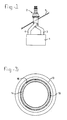
- Fig. 1 shows a furnace 1, for example for a water heater (not shown).
- An assembly 2 is connected to said boiler 1, which assembly has an air supply pipe 3 and a flue gas discharge pipe 4, running vertically. Along a certain part of the height the air supply pipe 3 runs in such a way that it surrounds the flue gas discharge pipe 4 concentrically. In that part of the assembly 2 where the pipes surround each other concentrically, said assembly projects through the roof 5, so that the two pipes 3, 4 open out into the atmosphere.
- Figs. 2 and 3 show the opening construction of the pipes 3, 4 in greater detail.
- the opening 6 of the air supply pipe 3 is situated at a substantial distance below the opening 7 of the flue gas discharge pipe 4.
- a cover cap 8 is placed concentrically around the flue gas discharge pipe 4 and, as shown, covers the opening of the air supply pipe 3.
- fresh air flows through the gap between the cover cap 8 and the air supply pipe 3 into the opening 6.
- Said fresh air is drawn in by, for example, a fan (not shown) disposed in the furnace 1.
- the object of the present invention is therefore that the condensation forming should be collected at points where there is least risk of ice forming, or that the condensation should be discharged into, for example, the sewerage system.
- the cover plate 9 is constructed in a special way at the surface facing the opening 7.
- the cover plate 9 is constructed at that side with a surface 11 which slopes from the peripheral edge of the cover plate 9 in the direction of the centre thereof towards the opening 7.
- liquid droplets 10 forming on said surface 11 will move towards the centre of the cover plate 9, and will accumulate to form larger liquid droplets which can be collected in the flue gas discharge pipe 4 situated axially below them.
- a collecting unit connected to the sewerage system is fitted in the bottom of the flue gas discharge system, for the purpose of discharging condensation which forms in the top part of the flue gas discharge pipe, i.e. before the opening 7 is reached, and precipitates on the inside walls of the flue gas discharge pipe.
- a collecting unit connected to the sewerage system is fitted in the bottom of the flue gas discharge system, for the purpose of discharging condensation which forms in the top part of the flue gas discharge pipe, i.e. before the opening 7 is reached, and precipitates on the inside walls of the flue gas discharge pipe.
- the assembly is also provided with a collecting bowl 12, which is fitted concentrically around the flue gas pipe 4, with axial space between them, and a ring 13 is fitted, also coaxially with the flue gas discharge pipe 4.
- the maximum external diameter of the ring 13 is made smaller in this case than the maximum internal diameter of the vessel 12.
- liquid droplets 10 which fall down outside the opening 7 from the cover plate 9 are collected on the ring 13. Flowing along the outside wall of the ring 13, the liquid droplets 10 ultimately reach the inside of the collecting bowl 12. If the capacity of the collecting bowl 12 is great enough, the liquid droplets 10 could remain collected therein, and evaporate uniformly, for example in warmer weather.
- the volume of the collecting bowl 12 should then be such that the collecting bowl 12 overflows possibly only in the most extreme circumstances (for example, a lengthy period of frost).
- the interior space of the collecting bowl 12 is in fluid communication with the flue gas discharge pipe 4.
- the wall of the collecting bowl 12 forms part of the flue gas discharge pipe 4.
- the ring 13 the top edge of which defines the opening 7.
- a pipe branch 14 is disposed inside the flue gas discharge pipe 4.
- Said pipe branch 14 runs from some distance axially below the bottom edge of the bowl 12 past the top edge of the collecting bowl 12, so that it bridges the axial gap between the collecting bowl 12 and the ring 13, and projects for some distance into the ring 13.
- the branch 14 has a relatively broad branch part 14' and a narrower branch part 14', with a conical transition part between them.
- the outside wall of the broader branch part 14" defines a relatively narrow gap with the inside wall of the flue gas discharge pipe 4.
- Said gap 15 extends over a considerable distance in the axial direction and is widened in a stepwise manner in the direction of the furnace 1 (Fig. 1).
- the annular space bounded between the collecting bowl 12 and the narrower branch part 14" is in fluid communication with the interior of the flue gas discharge pipe 4 below the branch 14.
- Droplets 10 can flow through this gap 15 out of the collecting bowl 12 and further down into the flue gas discharge pipe 4, and are then discharged to, for example, the sewer, as already explained above.
- the air resistance in the gap 15 is considerably greater than the air resistance in the branch 14. Combustion gases will therefore not escape through the gap 15 to the environment.
- the branch 14 is narrowed above the gap 15, which produces an acceleration of the flue gases in the area 13.
- the gap 15 runs all the way around. It is interrupted only at the position of the supporting strips 16, which run from the bottom side of the collecting bowl 12 to the cover plate 9.
- the branch 14 is connected by way of the supporting strips 16 to the flue gas discharge pipe 4, with a fixing flange of the cap 8 between them.
- the ring 13 and the cover plate 9 are also suspended from the supporting strips 16.
- the collecting bowl 12 is pushed tightly over the supporting strips 16, and is connected thereto by friction.
- the collecting bowl 12 can also be connected by mechanical fixing means or by welding to the supporting strips 16 or any other suitable supporting element, such as the flange of the cap 8 or the flue gas discharge pipe 4.
- the collecting bowl 12 can be provided in the bottom thereof with an annular pattern of holes, by means of which the fluid communication with the interior of the flue gas discharge pipe 4 is ensured. Said pattern of holes can then be arranged in such a way that flue gases do not escape from the flue gas discharge pipe 4 through said pattern of holes into the environment.
- the gap 15 can be wider.
- the underside of the branch 14 can, for example, be connected directly to the bottom of the collecting bowl 12, and does not then project further downwards.
- the narrowing in the branch 14 is not absolutely necessary. An acceleration of the gas flow through the branch 14 could also be achieved in another way.
- the collecting bowl 12 can also be shaped differently, for example with convex walls instead of the flat walls shown here. It could also have completely vertical side walls.
- the ring 13 may be omitted if desired, or it could be shaped differently if desired, for example with convex side walls.
- the inverted funnel shape thereof shown here is not absolutely essential.
- the axial gap between the collecting bowl 12 and the ring 13 may also be omitted, in which case, for example, the ring 13 projects into the collecting bowl 12. What is important is that the liquid droplets 10 falling vertically downwards from each surface higher up can be collected in the collecting bowl 12.
Landscapes
- Engineering & Computer Science (AREA)
- Chemical & Material Sciences (AREA)
- Combustion & Propulsion (AREA)
- Mechanical Engineering (AREA)
- General Engineering & Computer Science (AREA)
- Thermal Sciences (AREA)
- Physics & Mathematics (AREA)
- Chimneys And Flues (AREA)
- Joints Allowing Movement (AREA)
- Exhaust Silencers (AREA)
- Earth Drilling (AREA)
- Feeding And Controlling Fuel (AREA)
- Resistance Heating (AREA)
- Steam Or Hot-Water Central Heating Systems (AREA)
Claims (13)
- Rauchgasabfuhranordnung (2), die zur Verbindung mit der Rauchgasabfuhröffnung eines Verbrennungsofens, beispielsweise eines Heizkessels oder Warmwasserbereiters, geeignet ist und folgendes umfaßt: ein Rauchgasabfuhrrohr (4 14), das mit Auffangmitteln (12) zum Auffangen von Kondensation versehen ist, wobei ein den Querschnitt des Rauchgasrohrs (4, 14) bedeckendes Abdeckelement (9) in einem axialen Abstand von der von dem Ofen weg weisenden Öffnung des Rohrs angeordnet ist, so daß Fluidströmung zwischen dem Abdeckelement (9) und der Auslaßöffnung des Abfuhrrohrs gestattet wird, dadurch gekennzeichnet, daß die Auffangmittel ein Auffangschalenelement (12) umfassen, wobei der Umfang der Schale an das Abdeckelement (9) angepaßt und koaxial damit ist, wobei das Auffangschalenelement außerhalb des Rauchgasabfuhrrohrs (4, 14) angeordnet und mit dem Rohr verbunden ist, so daß außerhalb der Abfuhranordnung über der Schale (12) gebildete Kondensation in der Schale (12) aufgefangen wird, daß die Auffangmittel (12) in Strömungsverbindung mit dem Inneren des Rauchgasabfuhrrohrs (4) stehen, so daß in dem Auffangschalenelement (12) aufgefangene Flüssigkeit in das Rauchgasabfuhrrohr fließen kann.
- Rauchgasabfuhranordnung (2) nach Anspruch 1, dadurch gekennzeichnet, daß sich das Auffangschalenelement (12) um das Abfuhrrohr (4, 14) herum erstreckt und vorzugsweise damit koaxial ist.
- Rauchgasabfuhranordnung (2) nach einem oder mehreren der vorhergehenden Ansprüche, dadurch gekennzeichnet, daß über dem Auffangschalenelement (12) ein ringförmiges Element (13) angeordnet ist, das einen Tropfrand definiert, der innerhalb des nach oben weisenden Rands des Auffangschalenelements (12) liegt.
- Rauchgasabfuhranordnung nach Anspruch 3, dadurch gekennzeichnet, daß das ringförmige Element (13) Wände aufweist, die bezüglich der Längsrichtung des Rauchgasabfuhrrohrs (4, 14) geneigt sind.
- Rauchgasabfuhranordnung nach Anspruch 3 oder 4, dadurch gekennzeichnet, daß das ringförmige Element (13) in das Auffangschalenelement (12) hineinragt.
- Rauchgasabfuhranordnung nach Anspruch 3 und/oder 4, dadurch gekennzeichnet, daß zwischen dem Auffangschalenelement (12) und dem ringförmigen Element (13) ein axialer Abstand aufrechterhalten ist.
- Rauchgasabfuhranordnung (2) nach einem oder mehreren der Ansprüche 3 bis 6, dadurch gekennzeichnet, daß das Abdeckelement (9) über dem ringförmigen Element (13) angeordnet ist.
- Rauchgasabfuhranordnung nach einem der vorhergehenden Ansprüche, dadurch gekennzeichnet, daß das Abdeckelement (9) einen Wandteil (11) aufweist, der sich in Richtung der Öffnung des Rohrs (4) vom Umfang zur Mittellinie der Rohre (4, 13, 14) neigt.
- Rauchgasabfuhranordnung nach einem oder mehreren der vorhergehenden Ansprüche, dadurch gekennzeichnet, daß das Auffangschalenelement (12) über einen ringförmigen Spalt mit dem Inneren des Rohrs in Strömungsverbindung steht, während die Wände des ringförmigen Spalts so ausgeführt sind, daß im Vergleich zu dem Luftwiderstand im Rohr (4) ein beträchtlicher Luftwiderstand gegen die Gasströmung durch den Spalt hervorgerufen wird.
- Rauchgasabfuhranordnung nach einem oder mehreren der vorhergehenden Ansprüche, dadurch gekennzeichnet, daß das Auffangschalenelement (12) einen aus dem Abfuhrrohr (4) ragenden Rohrstutzen (14) umgibt und daß das Auffangbehälterelement (12) die Fortführung der Öffnung des Rohrs (4) definiert.
- Rauchgasabfuhranordnung nach Anspruch 11 in Kombination mit mindestens Anspruch 4, dadurch gekennzeichnet, daß der Rohrstutzen (14) in das ringförmige Element (13) mündet.
- Rauchgasabfuhranordnung (2) nach einem oder mehreren der vorhergehenden Ansprüche, dadurch gekennzeichnet, daß in dem Bereich innerhalb des Auffangschalenelements (12) Elemente zum Bewirken einer Beschleunigung des von dem Abfuhrrohr (4) kommenden oder dadurch strömenden Luftstroms angeordnet sind.
- Rauchgasabfuhranordnung (2) nach einem oder mehreren der vorhergehenden Ansprüche, dadurch gekennzeichnet, daß das Rauchgasabfuhrrohr (4) über mindestens einen Teil seiner Länge innerhalb eines Luftzufuhrrohrs (6) verläuft oder daß ein Luftzufuhrrohr über mindestens einen Teil seiner Länge innerhalb des Rauchgasabfuhrrohrs verläuft, und wobei die Rohre (4, 6) auf der von dem Ofen weg weisenden Seite bezüglich der Längsrichtung der Rohre in einem Abstand voneinander enden.
Priority Applications (1)
| Application Number | Priority Date | Filing Date | Title |
|---|---|---|---|
| DE29521681U DE29521681U1 (de) | 1994-04-25 | 1995-04-25 | Rauchgasabfuhranordnung |
Applications Claiming Priority (2)
| Application Number | Priority Date | Filing Date | Title |
|---|---|---|---|
| NL9400659 | 1994-04-25 | ||
| NL9400659A NL9400659A (nl) | 1994-04-25 | 1994-04-25 | Samenstel van luchttoevoer en/of verbrandingsgasafvoer voor aansluiting op een haard. |
Publications (3)
| Publication Number | Publication Date |
|---|---|
| EP0679841A1 EP0679841A1 (de) | 1995-11-02 |
| EP0679841B1 EP0679841B1 (de) | 1997-10-15 |
| EP0679841B2 true EP0679841B2 (de) | 2003-05-21 |
Family
ID=19864107
Family Applications (1)
| Application Number | Title | Priority Date | Filing Date |
|---|---|---|---|
| EP95201065A Expired - Lifetime EP0679841B2 (de) | 1994-04-25 | 1995-04-25 | Anordnung eines Luftzufuhrrohres und/oder eines Rauchgas-Abfuhrrohres für die Verbindung zu einem Ofen |
Country Status (5)
| Country | Link |
|---|---|
| EP (1) | EP0679841B2 (de) |
| AT (1) | ATE159335T1 (de) |
| DE (1) | DE69500864T2 (de) |
| DK (1) | DK0679841T4 (de) |
| NL (1) | NL9400659A (de) |
Cited By (1)
| Publication number | Priority date | Publication date | Assignee | Title |
|---|---|---|---|---|
| US7354244B2 (en) | 2004-09-01 | 2008-04-08 | Aos Holding Company | Blower and method of conveying fluids |
Families Citing this family (3)
| Publication number | Priority date | Publication date | Assignee | Title |
|---|---|---|---|---|
| DE29606539U1 (de) * | 1996-04-10 | 1997-08-07 | Interactive Holding B.V., Didam | Aufsatz für ein Abgasrohr einer Heizungsanlage |
| NL1003203C2 (nl) | 1996-05-24 | 1997-11-25 | Ubbink Nederland Bv | IJsvrije afvoerconstructie. |
| NL1005472C2 (nl) | 1997-03-07 | 1998-09-18 | Muelink & Grol Bv | Uitstroommondstuk voor rookgasafvoer van een verbrandingshaard. |
Citations (4)
| Publication number | Priority date | Publication date | Assignee | Title |
|---|---|---|---|---|
| NL180781C (nl) † | 1975-01-17 | 1987-04-16 | Leblanc Sa E L M | Buizensamenstel voor het door een wand geleiden van verbrandingsgas en lucht. |
| NL8701809A (nl) † | 1987-07-31 | 1989-02-16 | Antonius Gerardus Maria Mullin | Rookgasafvoersysteem. |
| NL9002786A (nl) † | 1990-12-17 | 1992-07-16 | Burgerhout Bv | Gecombineerde branderluchttoevoer en -verbrandingsgasafvoer. |
| DE4123614A1 (de) † | 1991-07-17 | 1993-01-28 | Heribert Von Goewels | Schornsteinkopf |
Family Cites Families (4)
| Publication number | Priority date | Publication date | Assignee | Title |
|---|---|---|---|---|
| US4280656A (en) * | 1979-05-04 | 1981-07-28 | Swanson Mervin D | Chimney heat economizer |
| NL192132B (nl) * | 1986-05-26 | 1996-10-01 | Metaalfab Burgerhout B V | Afvoerkanaal voor verbrandingsgassen voorzien van condensafvoer- middelen. |
| NL8801181A (nl) * | 1988-05-04 | 1989-12-01 | Metaalfab Burgerhout B V | Doorvoerpijp. |
| DE3929578A1 (de) * | 1989-09-06 | 1991-03-07 | Stiebel Eltron Gmbh & Co Kg | Abdeckhaube fuer einen schornstein |
-
1994
- 1994-04-25 NL NL9400659A patent/NL9400659A/nl not_active Application Discontinuation
-
1995
- 1995-04-25 DE DE69500864T patent/DE69500864T2/de not_active Expired - Lifetime
- 1995-04-25 EP EP95201065A patent/EP0679841B2/de not_active Expired - Lifetime
- 1995-04-25 AT AT95201065T patent/ATE159335T1/de active
- 1995-04-25 DK DK95201065T patent/DK0679841T4/da active
Patent Citations (4)
| Publication number | Priority date | Publication date | Assignee | Title |
|---|---|---|---|---|
| NL180781C (nl) † | 1975-01-17 | 1987-04-16 | Leblanc Sa E L M | Buizensamenstel voor het door een wand geleiden van verbrandingsgas en lucht. |
| NL8701809A (nl) † | 1987-07-31 | 1989-02-16 | Antonius Gerardus Maria Mullin | Rookgasafvoersysteem. |
| NL9002786A (nl) † | 1990-12-17 | 1992-07-16 | Burgerhout Bv | Gecombineerde branderluchttoevoer en -verbrandingsgasafvoer. |
| DE4123614A1 (de) † | 1991-07-17 | 1993-01-28 | Heribert Von Goewels | Schornsteinkopf |
Cited By (1)
| Publication number | Priority date | Publication date | Assignee | Title |
|---|---|---|---|---|
| US7354244B2 (en) | 2004-09-01 | 2008-04-08 | Aos Holding Company | Blower and method of conveying fluids |
Also Published As
| Publication number | Publication date |
|---|---|
| DE69500864T2 (de) | 1998-02-26 |
| DK0679841T3 (da) | 1998-02-23 |
| ATE159335T1 (de) | 1997-11-15 |
| EP0679841B1 (de) | 1997-10-15 |
| DE69500864D1 (de) | 1997-11-20 |
| DK0679841T4 (da) | 2003-11-03 |
| EP0679841A1 (de) | 1995-11-02 |
| NL9400659A (nl) | 1995-12-01 |
Similar Documents
| Publication | Publication Date | Title |
|---|---|---|
| US4603680A (en) | Furnace inducer outlet box assembly | |
| US4481935A (en) | Flue pipe connection | |
| EP0679841B2 (de) | Anordnung eines Luftzufuhrrohres und/oder eines Rauchgas-Abfuhrrohres für die Verbindung zu einem Ofen | |
| JP2008175047A (ja) | 雨樋融雪装置 | |
| US20090017746A1 (en) | Apparatus having a heated screen for melting ice, snow or the like | |
| US5531543A (en) | Device for ensuring free water passage to roof rainwater outlets in connection with ice formation | |
| US3522767A (en) | Adjustable chimney t | |
| US3596587A (en) | Offtake for cooking equipment | |
| US4583494A (en) | Heat recovery apparatus and heat recovery method | |
| CZ292376B6 (cs) | Nástavec pro odtahové potrubí topného zařízení | |
| HU205648B (en) | Chimeny cap for multiple-shell house-chimneys of bypass-canal ventilation | |
| WO1985003993A1 (en) | Chimney | |
| US4425901A (en) | Heat exchange device | |
| EP0809074B1 (de) | Eisbildungsfreier Abfuhraufbau | |
| US5000217A (en) | Apparatus for keeping a rain water well unfrozen | |
| US3330233A (en) | Clements chimneys | |
| NL8703097A (nl) | Schoorsteen met condensafvoer. | |
| US11103818B2 (en) | Filter device and water heater | |
| EP1365194B1 (de) | Kaminkopf | |
| JP2582808Y2 (ja) | 煙 突 | |
| JPH0750533Y2 (ja) | 屋根下設置型融雪装置 | |
| GB2074706A (en) | Float controlled draw off tube for hot water storage tank | |
| NL1005472C2 (nl) | Uitstroommondstuk voor rookgasafvoer van een verbrandingshaard. | |
| AU782773B2 (en) | Exhaust fan canopy apparatus | |
| US2930308A (en) | Soot shield for chimneys |
Legal Events
| Date | Code | Title | Description |
|---|---|---|---|
| PUAI | Public reference made under article 153(3) epc to a published international application that has entered the european phase |
Free format text: ORIGINAL CODE: 0009012 |
|
| AK | Designated contracting states |
Kind code of ref document: A1 Designated state(s): AT BE CH DE DK FR GB IT LI LU NL |
|
| 17P | Request for examination filed |
Effective date: 19960502 |
|
| 17Q | First examination report despatched |
Effective date: 19960925 |
|
| GRAG | Despatch of communication of intention to grant |
Free format text: ORIGINAL CODE: EPIDOS AGRA |
|
| GRAG | Despatch of communication of intention to grant |
Free format text: ORIGINAL CODE: EPIDOS AGRA |
|
| GRAH | Despatch of communication of intention to grant a patent |
Free format text: ORIGINAL CODE: EPIDOS IGRA |
|
| GRAH | Despatch of communication of intention to grant a patent |
Free format text: ORIGINAL CODE: EPIDOS IGRA |
|
| GRAA | (expected) grant |
Free format text: ORIGINAL CODE: 0009210 |
|
| AK | Designated contracting states |
Kind code of ref document: B1 Designated state(s): AT BE CH DE DK FR GB IT LI LU NL |
|
| REF | Corresponds to: |
Ref document number: 159335 Country of ref document: AT Date of ref document: 19971115 Kind code of ref document: T |
|
| REG | Reference to a national code |
Ref country code: CH Ref legal event code: EP |
|
| REF | Corresponds to: |
Ref document number: 69500864 Country of ref document: DE Date of ref document: 19971120 |
|
| REG | Reference to a national code |
Ref country code: CH Ref legal event code: NV Representative=s name: R. A. EGLI & CO. PATENTANWAELTE |
|
| ITF | It: translation for a ep patent filed | ||
| ET | Fr: translation filed | ||
| REG | Reference to a national code |
Ref country code: DK Ref legal event code: T3 |
|
| PG25 | Lapsed in a contracting state [announced via postgrant information from national office to epo] |
Ref country code: DE Free format text: LAPSE BECAUSE OF THE APPLICANT RENOUNCES Effective date: 19980420 |
|
| PLBQ | Unpublished change to opponent data |
Free format text: ORIGINAL CODE: EPIDOS OPPO |
|
| PLBQ | Unpublished change to opponent data |
Free format text: ORIGINAL CODE: EPIDOS OPPO |
|
| PLBI | Opposition filed |
Free format text: ORIGINAL CODE: 0009260 |
|
| PLBF | Reply of patent proprietor to notice(s) of opposition |
Free format text: ORIGINAL CODE: EPIDOS OBSO |
|
| 26 | Opposition filed |
Opponent name: COX GELEEN B.V. Effective date: 19980715 Opponent name: INTERACTIVE BOUWPRODUKTEN B.V. Effective date: 19980713 |
|
| NLR1 | Nl: opposition has been filed with the epo |
Opponent name: COX GELEEN B.V. Opponent name: INTERACTIVE BOUWPRODUKTEN B.V. |
|
| PLBF | Reply of patent proprietor to notice(s) of opposition |
Free format text: ORIGINAL CODE: EPIDOS OBSO |
|
| PLBF | Reply of patent proprietor to notice(s) of opposition |
Free format text: ORIGINAL CODE: EPIDOS OBSO |
|
| PLBF | Reply of patent proprietor to notice(s) of opposition |
Free format text: ORIGINAL CODE: EPIDOS OBSO |
|
| PLBQ | Unpublished change to opponent data |
Free format text: ORIGINAL CODE: EPIDOS OPPO |
|
| PLAB | Opposition data, opponent's data or that of the opponent's representative modified |
Free format text: ORIGINAL CODE: 0009299OPPO |
|
| R26 | Opposition filed (corrected) |
Opponent name: INTERACTIVE BOUWPRODUKTEN B.V. * 19980715 COX-GEEL Effective date: 19980713 |
|
| NLR1 | Nl: opposition has been filed with the epo |
Opponent name: COX-GEELEN B.V. Opponent name: INTERACTIVE BOUWPRODUKTEN B.V. |
|
| PLBQ | Unpublished change to opponent data |
Free format text: ORIGINAL CODE: EPIDOS OPPO |
|
| PLAB | Opposition data, opponent's data or that of the opponent's representative modified |
Free format text: ORIGINAL CODE: 0009299OPPO |
|
| R26 | Opposition filed (corrected) |
Opponent name: INTERACTIVE BOUWPRODUKTEN B.V. * 19980715 COX-GEEL Effective date: 19980713 |
|
| PLAW | Interlocutory decision in opposition |
Free format text: ORIGINAL CODE: EPIDOS IDOP |
|
| NLR1 | Nl: opposition has been filed with the epo |
Opponent name: COX-GEELEN B.V. Opponent name: INTERACTIVE BOUWPRODUKTEN B.V. |
|
| APAC | Appeal dossier modified |
Free format text: ORIGINAL CODE: EPIDOS NOAPO |
|
| APAE | Appeal reference modified |
Free format text: ORIGINAL CODE: EPIDOS REFNO |
|
| APAC | Appeal dossier modified |
Free format text: ORIGINAL CODE: EPIDOS NOAPO |
|
| APCC | Communication from the board of appeal sent |
Free format text: ORIGINAL CODE: EPIDOS OBAPO |
|
| REG | Reference to a national code |
Ref country code: GB Ref legal event code: IF02 |
|
| PLBQ | Unpublished change to opponent data |
Free format text: ORIGINAL CODE: EPIDOS OPPO |
|
| PLAB | Opposition data, opponent's data or that of the opponent's representative modified |
Free format text: ORIGINAL CODE: 0009299OPPO |
|
| APCC | Communication from the board of appeal sent |
Free format text: ORIGINAL CODE: EPIDOS OBAPO |
|
| R26 | Opposition filed (corrected) |
Opponent name: INTERACTIVE BOUWPRODUKTEN B.V. * 19980715 COX-GEEL Effective date: 19980713 |
|
| APCC | Communication from the board of appeal sent |
Free format text: ORIGINAL CODE: EPIDOS OBAPO |
|
| NLR1 | Nl: opposition has been filed with the epo |
Opponent name: COX-GEELEN B.V. Opponent name: INTERACTIVE BOUWPRODUKTEN B.V. |
|
| APCC | Communication from the board of appeal sent |
Free format text: ORIGINAL CODE: EPIDOS OBAPO |
|
| APAC | Appeal dossier modified |
Free format text: ORIGINAL CODE: EPIDOS NOAPO |
|
| PLAW | Interlocutory decision in opposition |
Free format text: ORIGINAL CODE: EPIDOS IDOP |
|
| PUAH | Patent maintained in amended form |
Free format text: ORIGINAL CODE: 0009272 |
|
| STAA | Information on the status of an ep patent application or granted ep patent |
Free format text: STATUS: PATENT MAINTAINED AS AMENDED |
|
| 27A | Patent maintained in amended form |
Effective date: 20030521 |
|
| AK | Designated contracting states |
Designated state(s): AT BE CH DE DK FR GB IT LI LU NL |
|
| NLR1 | Nl: opposition has been filed with the epo |
Opponent name: COX-GEELEN B.V. Opponent name: INTERACTIVE BOUWPRODUKTEN B.V. |
|
| REG | Reference to a national code |
Ref country code: CH Ref legal event code: AEN Free format text: MAINTIEN DU BREVET DONT L'ETENDUE A ETE MODIFIEE |
|
| NLR2 | Nl: decision of opposition |
Effective date: 20030521 |
|
| ET3 | Fr: translation filed ** decision concerning opposition | ||
| NLR3 | Nl: receipt of modified translations in the netherlands language after an opposition procedure | ||
| REG | Reference to a national code |
Ref country code: DK Ref legal event code: T4 |
|
| APAH | Appeal reference modified |
Free format text: ORIGINAL CODE: EPIDOSCREFNO |
|
| PGFP | Annual fee paid to national office [announced via postgrant information from national office to epo] |
Ref country code: NL Payment date: 20140122 Year of fee payment: 20 |
|
| PGFP | Annual fee paid to national office [announced via postgrant information from national office to epo] |
Ref country code: LU Payment date: 20140423 Year of fee payment: 20 |
|
| PGFP | Annual fee paid to national office [announced via postgrant information from national office to epo] |
Ref country code: GB Payment date: 20140430 Year of fee payment: 20 |
|
| PGFP | Annual fee paid to national office [announced via postgrant information from national office to epo] |
Ref country code: FR Payment date: 20140430 Year of fee payment: 20 Ref country code: CH Payment date: 20140425 Year of fee payment: 20 Ref country code: AT Payment date: 20140425 Year of fee payment: 20 Ref country code: IT Payment date: 20140423 Year of fee payment: 20 |
|
| PGFP | Annual fee paid to national office [announced via postgrant information from national office to epo] |
Ref country code: BE Payment date: 20140527 Year of fee payment: 20 Ref country code: DK Payment date: 20140425 Year of fee payment: 20 |
|
| REG | Reference to a national code |
Ref country code: DK Ref legal event code: EUP Effective date: 20150425 |
|
| REG | Reference to a national code |
Ref country code: CH Ref legal event code: PL |
|
| REG | Reference to a national code |
Ref country code: GB Ref legal event code: PE20 Expiry date: 20150424 |
|
| REG | Reference to a national code |
Ref country code: AT Ref legal event code: MK07 Ref document number: 159335 Country of ref document: AT Kind code of ref document: T Effective date: 20150425 |
|
| PG25 | Lapsed in a contracting state [announced via postgrant information from national office to epo] |
Ref country code: GB Free format text: LAPSE BECAUSE OF EXPIRATION OF PROTECTION Effective date: 20150424 |