EP0679886B1 - Spectromètre de mobilité ionique - Google Patents
Spectromètre de mobilité ionique Download PDFInfo
- Publication number
- EP0679886B1 EP0679886B1 EP95106269A EP95106269A EP0679886B1 EP 0679886 B1 EP0679886 B1 EP 0679886B1 EP 95106269 A EP95106269 A EP 95106269A EP 95106269 A EP95106269 A EP 95106269A EP 0679886 B1 EP0679886 B1 EP 0679886B1
- Authority
- EP
- European Patent Office
- Prior art keywords
- ion
- mobility spectrometer
- set forth
- ion mobility
- electrode
- Prior art date
- Legal status (The legal status is an assumption and is not a legal conclusion. Google has not performed a legal analysis and makes no representation as to the accuracy of the status listed.)
- Expired - Lifetime
Links
Images


Classifications
-
- G—PHYSICS
- G01—MEASURING; TESTING
- G01N—INVESTIGATING OR ANALYSING MATERIALS BY DETERMINING THEIR CHEMICAL OR PHYSICAL PROPERTIES
- G01N27/00—Investigating or analysing materials by the use of electric, electrochemical, or magnetic means
- G01N27/62—Investigating or analysing materials by the use of electric, electrochemical, or magnetic means by investigating the ionisation of gases, e.g. aerosols; by investigating electric discharges, e.g. emission of cathode
- G01N27/622—Ion mobility spectrometry
- G01N27/624—Differential mobility spectrometry [DMS]; Field asymmetric-waveform ion mobility spectrometry [FAIMS]
-
- G—PHYSICS
- G01—MEASURING; TESTING
- G01N—INVESTIGATING OR ANALYSING MATERIALS BY DETERMINING THEIR CHEMICAL OR PHYSICAL PROPERTIES
- G01N33/00—Investigating or analysing materials by specific methods not covered by groups G01N1/00 - G01N31/00
- G01N33/22—Fuels; Explosives
Definitions
- the present invention relates to ion mobility spectrometry and in particular to an ion mobility spectrometer capable of both quantitative as well as qualitative analysis of trace level species.
- IMS Ion Mobility Spectrometry
- IMS Ion Mobility Spectrometry
- a sample gas alone or in combination with a carrier gas is directed into an ionization region containing a source of ionization, typically a ⁇ -emitter, and accelerated into a drift region where they are separated based on mass, charge and size of the ions.
- a detector such as an electrometer amplifier.
- An important variant of the IMS device is a transverse field compensation IMS which utilizes two electrodes to provide an analyzing region between the ionization zone and the ion detection region. The analyzing region is set to a selected set of potentials which permits certain ions to transverse the analytical region to reach a detector such as an electrometer.
- T the period of the electric field
- t the current time
- the mean drift velocity depends on the quadratic and higher order terms of the expansion for k given by Equation (1).
- U.S. Patent No. 3,699,333 discloses a method and apparatus for sorting and detecting trace gases using ion-molecular reactions in a drift field located between an ion forming region and detection region.
- U.S. Patent No. 3,935,452 a quadrapole mobility spectrometer is described. This device utilizes a carrier gas mixed with gas and ions directed between the quadrapole electrode which has impressed therebetween a hyperbolic electric field.
- a gas analyzer which can provide an extended dynamic range over a wide variety of ionic species. It is a further object of the invention to provide an IMS analyzer which provides a secondary and tertiary means of resolution. It is also an object of the invention to provide an ion spectrometer which can be made to be portable and detect trace levels of species in air at a threshold sensitivity of about 10 -11 g/liter. It is also an object of the invention to provide an analysis of the species at a distance remote from the actual source of up to 10 cm or more. It is a further object of the invention to provide an analyzer for the remote detection of drugs or explosives or other chemicals for which detection is desired at very low threshold limits.
- an ion mobility spectrometer comprises
- the present invention provides an ion mobility spectrometer which can be configured in a portable mode for the detection of species in the range of about 10 -11 g/liter.
- the invention comprises a housing having a first sample media inlet and a media outlet.
- a second inlet or source of carrier gas is also provided into the housing.
- the sample media is a gas or vapor, however, solids such as proteins, virus, organic polymers, and the like can be sampled.
- the first inlet and outlet allow access of a gas to be sampled into the spectrometer, preferably by a small pump attached to the outlet. This configuration is particularly useful where the spectrometer is configured for use as a small portable detector used in detecting explosives or drugs.
- an analyzer Positioned within the housing is an analyzer which is made up of first and second spaced apart electrodes.
- the electrodes are preferably longitudinal to a gas flow and define an analytical gap.
- the analytical gap is defined by parallel or concentrically positioned electrodes depending upon whether the spectrometer is planar or cylindrical.
- the analytical gap is in direct communication with a second inlet or an internal source of carrier gas from a recirculation loop.
- An ion outlet is located at the end of the analytical gap opposite from the second inlet.
- An ionization source is located in juxtaposition with the sample media inlet and the analytical gap.
- An ion aperture defines an opening to provide communication between the ionization source and the analytical gap so that ions created by the ionization source can migrate into the analytical gap preferably under the influence of an electric field.
- a small amount of carrier gas is encouraged through the aperture and away from the analytical gap to prevent nonionized sample media from entering the gap.
- the ionizer may be a ⁇ -emitter, photoionizer, corona discharge ionizer, electrospray or thermal ionizer.
- An ionkicker (or device for supplying an electric field to assist in ion migration from the ionization source into the analytical gap) is positioned adjacent the aperture. The ionkicker can be a third electrode or part of the ionization structure itself.
- an electrical controller is connected to the first and second electrodes to impress first and second electrical potentials therebetween.
- a third electrode normally the ionization source, is positioned proximate the ion aperture and connected to the electrical controller.
- the first electrical potential difference is a constant or slowly varying unidirectional compensating potential (hereinafter "compensation voltage") created between the first and second electrodes. The polarity of this potential difference depends upon the species to be detected.
- the second potential in series with the first, is an asymmetrical periodic potential impressed between the first and second electrodes. The first and second electrical potentials cause the transverse oscillation of the ions in the analytical gap. Ions traversing the length of the gap exit through the ion outlet for detection and measurement.
- An ion detector is located adjacent to the ion outlet and preferably includes a collector plate positioned adjacent to the outlet. Ions exiting the analytical gap are detected and measured on the collector plate. If specific species are sought to be detected, the biased collector plate can be connected to an electrometer amplifier to produce a signal upon detection of the desired species. On the other hand, if the invention is to be used to detect the presence of species, a record of ion current versus compensation voltage (hereinafter "ionogram”) can be generated from the output of the collector when connected to a recording device.
- ionogram ion current versus compensation voltage
- the spectrometer of the preferred embodiments can be packaged in a very small and light weight housing to facilitate portability or ease of handling.
- control of the compensation and asymmetrical periodic potentials affords supervisory control over resolution while biasing of the ionkicker can be used to enhance the device's dynamic range.
- transverse ion mobility spectrometer 10 of the present invention comprises a housing 11 preferably made from a light weight material such as aluminum, brass or Lexan® with a metal coating for shielding or to accept a common potential.
- housing 11 is cylindrical and approximately 65mm in diameter and 250mm in length.
- analyzer 12 Positioned within housing 11 is analyzer 12 which is concentrically supported therein by means of support members 13 and 14, respectively.
- analyzer 12 is planar and in a more preferred embodiment it is cylindrical.
- Support members 13 and 14 are made an insulating material such as Teflon®, a ceramic or like rigid material.
- Housing 11 includes first and second inlets 16 and 17 and outlets 18 and 19, respectively.
- First inlet 16 and outlet 19 are associated with a source of carrier gas such as dry air for carrying and/or diluting the species to be analyzed.
- the carrier gas is located externally to housing 11, but in certain applications, such as where the spectrometer is portable, a closed loop between inlet 16 and outlet 19 can be configured with a filtering media interposed. In the latter case, only one inlet and outlet to the housing are required.
- Inlet 17 is connected to a source of media to be sampled.
- Such source can include a probe flexibly mounted to housing 11 and inlet 17 to obtain samples for detection and analysis.
- at least one pump is connected to outlet 18 to draw the sampled gas through inlet 17 and analyzer 12. While not shown, the pump may be a vortex, diaphragm, vacuum or like pump capable of providing a slight negative pressure within analyzer 12. In a portable mode, the pump is powered by small rechargeable batteries, not shown.
- Analyzer 12 comprises a first electrode 21 extending between and supported by support members 13 and 14, respectively.
- a second electrode 22 is precisely aligned concentrically within first electrode 21 by means of supports 23 and 24.
- electrodes 21 and 22 are elongated flat plates spaced in a parallel relationship, one to the other.
- electrodes 21 and 22 are cylinders in which electrode 22 is concentrically located within electrode 21.
- supports 23 and 24 each comprise a plurality, e.g. two sets of three insulating balls made preferably of sapphire and positioned in a Teflon® member, not shown. The space between first and second electrodes 21 and 22 defines analytical gap 25.
- the space defining analytical gap 25 is 1 to 3 mm and preferably about 2 mm having a length of from 8 to 12 mm. As shown in Figure 1, where electrodes 21 and 22 are cylindrical, a preferred inner diameter of electrode 21 is 18 mm and the preferred outer diameter of electrode 22 is 14 mm.
- the ionization source includes ionization chamber 28.
- Ionization chamber 28 is designed to separate the flow of carrier gas from the flow of sample media.
- chamber 28 defines a passageway 26 with electrode 21 for conveyance of a carrier gas.
- Passageway 26 includes a diffuser 31, in this embodiment, chamber 28 is preferably of a diameter slightly (e.g. .01 to .02 mm) less than the second electrode.
- the space between chamber 28 and analytical gap 25 is an ion aperture 29 which permits ionized species of the sample media to migrate into analytical gap 25. Aperture 29 is approximately 0.5 to 4 mm wide.
- Ionizer 30 may consist of a ⁇ -source ionizer such as tritium for the production of negative and positive ions or may consist of an electronic ionizer such as a corona discharge, electrospray or a photoionization source. While ⁇ -ionization sources require regulatory agency licensing, they avoid additional electrical power requirements which is important for portable instruments. If electrical power is not a concern, it is preferable to utilize electronic or photoionization when portability is desired.
- ⁇ -source ionizer such as tritium for the production of negative and positive ions
- an electronic ionizer such as a corona discharge, electrospray or a photoionization source. While ⁇ -ionization sources require regulatory agency licensing, they avoid additional electrical power requirements which is important for portable instruments. If electrical power is not a concern, it is preferable to utilize electronic or photoionization when portability is desired.
- ionizer 30 is connected to electrode 32 which is supported adjacent, but spaced apart from second electrode 22 by spacer 33 made of insulating material and having a plurality of openings 34 therethrough to permit the passage of sample media.
- ionizer 30 functions as a third electrode and part of the ionkicker.
- plug 38 Positioned adjacent to said openings 37 is plug 38 preferably made of an insulating material such as Teflon® , ceramic or like rigid material. In a cylindrical configuration, plug 38 is annular and prevents the media in analytical gap 25 from exiting therefrom except though openings 37. Juxtaposed to openings 37 is ion detector 40.
- Ion detector 40 comprises an collector plate 41 positioned normally or angularly offset (90°-45°) to the axes of openings 37.
- Collector plate 41 is preferably cantilevered over the openings by means of annular detector ring 42 made of an insulating material and having at least one lead 43 therethrough connected to collector plate 41.
- disk electrode 46 Preferably positioned on second support member 14 adjacent to openings 37 is disk electrode 46 used to help accelerate the ions toward collector place 41 by electrical migration.
- Ion species exiting openings 37 are detected on collector plate 41.
- Collector plate 41 is electrically connected to display or recording means for providing a signal upon detection of a threshold level of preselected species or for preparing ionograms to determine the constituents of a particular sampled media.
- Detector 40 is also preferably biased with a potential to accelerate the flow of ions to it.
- An electrical controller 50 is provided to generate and control an electric potential between the first and second electrodes.
- a first compensating unidirectional voltage is supplied by controller 50 via line 51 to first electrode 21, which is generally operated at circuit common, and to second electrode 22 by line 52.
- the voltage supplied is in the range of ⁇ 10 to ⁇ 600 volts.
- an asymmetrical periodic potential is impressed (in series with the unidirectional compensating potential) on second electrode 22 from controller 50 through line 52.
- Controller 50 can include portable rechargeable power sources such as NiCd or Li anode batteries known in the art. Generation of the asymmetric waveform can be accomplished through the use of conventional circuits including invertors and the like. Potentiometer, manual, or automatic sweeping or scanning can be used to vary the electric potential applied to the electrodes. Controller 50 is designed to provide the electrical condition necessary to resolve or map a specific ionic species.
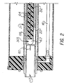
- a preferred embodiment of the invention is shown using a corona discharge for ionization.
- ionization of the sample media is effected by corona discharge and takes place adjacent the tip of corona wire 60 of ionizer 30 which is connected to power controller 50 through electrode 32.
- the corona discharge wire 60 is driven by a bidirectional waveform, preferably an asymmetrical high voltage RF waveform.
- electrode shield 64 is included. Electrode shield 64 is supported by insulator 66. Attached to the front of insulator 66 is the leading edge 67 of which is preferably rounded aluminum or like metal to reduce or eliminate turbulence of the sample media.
- Edge 67 is maintained at the same potential as electrode 32. Further, when using an asymmetrical waveform to drive the discharge, it is important to have the polarity of this waveform agree with that of the waveform which produces the asymmetrical potential impressed between first and second electrode 21 and 22, respectively.
- an asymmetrical high voltage RF waveform is used. Peak voltages of 2 kv have been found advantageous.
- Shield electrode 64 and electrode 32 as well as corona discharge wire 60 are set at the same d.c. voltage from about +20 vdc - ⁇ +300 vdc for positive ions and from about -20 vdc to +600 vdc for negative ions. This has the effect of forcing the ions of ionization chamber 28 through ion aperture 29 into analytical gap 25.
- sample media is drawn into spectrometer 10 through inlet 17.
- Sample media may be, for example, ambient air being sampled to detect the presence of certain gases such as chlorine, toluene, benzene, the presence of an explosive such TNT, and like other ionizable materials.
- the sample media is drawn into ionization chamber 28 by the effect of a small pump creating a negative pressure at outlet 18.
- carrier gas is introduced into plenum 26 through first inlet 16.
- the carrier gas acts as bulk transport mechanism for the ions moving longitudinally in gap 25.
- the carrier gas is preferably introduced so as to maintain a laminar flow through analytical gap 25.
- Plenum 26 is an annular chamber surrounding ionization chamber 28 in direct communication with analytical gap 25.
- the carrier gas is dehumidified air.
- carrier gas is introduced at the inlet 17 in amount of from 2.5 to 5.0/min and is exhausted at the rate of 0.5 to 3.5 l/min. from outlet 19. The remaining flow is preferably directed through ion aperture 29 to be exhausted with sample media through outlet 18.
- This flow rate provides an analytical time of about 0.1 to 1.3 seconds in gap 25 depending upon the length of the gap. However, if the time is too long, none of the ions of interest get measured due to loss mechanisms such as diffusion and charge transfer.
- ionization source 30 Sample media drawn into chamber 28 is ionized by ionization source 30. If that source is tritium, positive and negative ions are created the same as with ionization by corona discharge.
- the radioactive source material is mounted on ionizer 30 which is connected to power controller 50 via electrode 32. Electrical potentials are applied to chamber 28, ionizer 30 (via electrode 32) and electrode 22, such that the ions formed in chamber 28 are driven through aperture 29 and into analytical gap 25. For positive ions the potentials applied to these electrodes would be: chamber 28; circuit common ionizer 30 and electrode 32, +20 to +300 vdc; electrode 22, compensation voltage typically between -1 and -100 vdc.
- the potentials applied to these electrodes would be: chamber 28; circuit common; ionizer 30 and electrode 32, -20 to -600 vdc; electrode 22, compensation voltage typically between +1 and +100 vdc.
- These same voltage configurations apply for operation of the corona discharge ionization, except shield electrode 64 is introduced between electrodes 22 and 32.
- ionizer 30, electrode 32 and shield electrode 64 are maintained at the same dc potential while and additional high voltage RF potential is applied to ionizer 30 and electrode 32 which induces the corona breakdown at the tip corona discharge wire 60.
- the ions move in the direction perpendicular to the direction of the air flow due to the influence of the asymmetric periodic potential impressed on the second electrode 22 by controller 50.
- the amplitude of the asymmetric periodic potential is in the range of 1 to 6 Kv and preferably in the range of about 2 to 5 Kv and more preferably about 3 Kv depending of the ionic species of interest.
- the compensation voltage can be held constant or scanned to provide separation of the ionic species.
- other waveforms may be used so long as they comply with the general expression ⁇ o T V 3 (t) dt ⁇ 0.
- Detector 40 may include electrometric registration of ions such as taught and described in U.S. Patent No. 3,668,388 which is incorporated by reference herein.
- a third bias voltage consisting of a low frequency ( ⁇ 100 Hz) "ripple" voltage is impressed in series with the above mentioned voltages between electrodes 21 and 22 and enhances the resolution in the cylindrical analyzer 12. This potential tends to narrow the effective gap between electrodes 21 and 22 and reduces the depth of the virtual potential well existing in gap 25 for those ions which are appropriately compensated.
- the instrument's sensitivity and dynamic range can be adjusted. For example, as shown in Figure 8 when the bias between chamber 28 and ionizer 30 is between -20 and -30 vdc, the sensor's response to Cl 2 is maximized. However, by increasing this voltage to -600 vdc, the sensitivity is reduced and the dynamic range is increased. This adjustment has no adverse affect on the sensor's resolution.
- the amplitude of the second compensation voltage which must be applied between electrodes 21 and 22 will depend on the ion species of interest and the amplitude of the first asymmetric periodic voltage applied between electrodes 21 and 22.
- the amplitude of the compensation voltage required for that species will likewise increase.
- the functional relationship between the amplitude of the periodic asymmetric voltage and the amplitude of the constant voltage required to compensate will depend on the identity of the ionic species involved.
- Curve A of Figure 5 is an ionogram where the sample stream contained 100 ppm of o-xylene.
- Curve B of Figure 5 is an ionogram recorded under conditions identical to those which existed with respect to Curve A, except the sample stream contained a combination of 100 ppm o-xylene and 10ppb DMMP.
- Curve A the o-xylene produces a strong feature in the ionogram at a compensation voltage of 6V.
- Curve B the feature due to DMMP occurs at almost the same compensation voltage.
- Curve B it is difficult to isolate the o-xylene and DMMP related features, which impedes both qualitative and quantitative analysis of the original stream's composition.
- DMMP dimethyl methyl phosphonate
- the middle curve A is the spectrum of ⁇ 10 ppb DMMP in clean air.
- Spectrum B and C respectively, represent the clean air ionogram before and after spectrometer 10 was tested with DMMP.
- the ionogram represents a sample stream having 10 ppb DMMP and 5 ppm benzene.
- the DMMP peak at ⁇ 6 vdc and benzene at ⁇ 7.5 vdc are clearly shown. Similar tests with toluene produced ionograms likewise resolved.
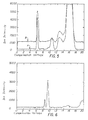
- FIG. 7 two ionograms of DMMP in air are shown.
- the sample media was ionized by traditional tritium ⁇ -emitter, while in Figure 7b the ionization was produced by the corona discharge ionizer shown in Figure 2.
- an asymmetrical high voltage having a peak amplitude of about 2 kv, was applied to discharge wire 60 via electrode 32 to form the corona discharge.
- the shield electrode 64 and electrode 32 were maintained at the same d.c. voltage ⁇ + 20 volts.
Landscapes
- Physics & Mathematics (AREA)
- Spectroscopy & Molecular Physics (AREA)
- Chemical & Material Sciences (AREA)
- Chemical Kinetics & Catalysis (AREA)
- Electrochemistry (AREA)
- Health & Medical Sciences (AREA)
- Life Sciences & Earth Sciences (AREA)
- Analytical Chemistry (AREA)
- Biochemistry (AREA)
- General Health & Medical Sciences (AREA)
- General Physics & Mathematics (AREA)
- Immunology (AREA)
- Pathology (AREA)
- Other Investigation Or Analysis Of Materials By Electrical Means (AREA)
Claims (16)
- Spectromètre à mobilité d'ions comprenant :dans lequel le dispositif de commande électrique (50) comprend un troisième potentiel de polarisation entre les première (21) et deuxième (22) électrodes, ledit troisième potentiel de polarisation comprenant une tension à ondulation de basse fréquence.un boítier (11) comportant au moins un orifice d'entrée (16 ; 17) pour la communication avec un milieu d'échantillon et au moins un orifice de sortie (18 ; 19) ;un analyseur (12) positionné à l'intérieur dudit boítier (11), comprenant :i. au moins des première (21) et deuxième (22) électrodes longitudinalement espacées l'une de l'autre, ledit espace entre lesdites électrodes définissant un espace d'analyse longitudinal (25), ledit espace (25) étant en communication avec une source de gaz porteur pour l'écoulement à travers celui-ci,ii. une source d'ionisation (30) juxtaposée audit espace d'analyse (25) et en communication avec ledit orifice d'entrée pour l'ionisation du milieu d'échantillon,iii. une ouverture d'ions (29) définissant une ouverture entre ladite source d'ionisation (30) et ledit espace d'analyse (25),iv. une troisième électrode (32) positionnée à proximité de ladite ouverture d'ions,v. au moins une ouverture de sortie (37) à partir dudit espace d'analyse éloignée de ladite ouverture d'ions,vi. un détecteur d'ions (40) pour mesurer les ions à partir dudit espace d'analyse, et espacé desdites électrodes, etvii. un dispositif de commande électrique (50) connecté auxdites électrodes pour communiquer des potentiels en courant continu auxdites première, deuxième et troisième électrodes (21, 22, 32) et pour communiquer un potentiel asymétrique périodique auxdites première et deuxième électrodes (21, 32), lesdits potentiels étant susceptibles de créer un champ électrique transversal entre elles durant l'écoulement de gaz porteur dans l'espace d'analyse,
- Spectromètre à mobilité d'ions selon la revendication 1, dans lequel lesdites première et deuxième électrodes sont cylindriques et alignées coaxialement.
- Spectromètre à mobilité d'ions selon la revendication 1, dans lequel lesdites première et deuxième électrodes sont planes.
- Spectromètre à mobilité d'ions selon la revendication 1, dans lequel ladite troisième électrode comprend la source d'ionisation.
- Spectromètre à mobilité d'ions selon la revendication 1, dans lequel ladite source d'ionisation est sélectionnée parmi le groupe comprenant les émetteurs , les photo-ioniseurs, les ioniseurs à décharge à effet en couronne, les électropulvérisateurs et les ioniseurs thermiques.
- Spectromètre à mobilité d'ions selon la revendication 2, dans lequel ladite source d'ionisation comprend une chambre d'ions coaxialement alignée avec ladite deuxième électrode et espacée de celle-ci pour définir ladite ouverture d'ions.
- Spectromètre à mobilité d'ions selon la revendication 1, dans lequel ledit boítier comprend un deuxième orifice d'entrée en communication avec ledit espace d'analyse, ledit deuxième orifice d'entrée étant connecté à une source de gaz porteur.
- Spectromètre à mobilité d'ions selon la revendication 1, dans lequel ledit boítier comprend un autre orifice d'entrée, connecté à une source de gaz porteur.
- Spectromètre à mobilité d'ions selon la revendication 1, dans lequel ledit potentiel asymétrique périodique crée un champ compris entre 5 kV/cm et 30 kV/cm.
- Spectromètre à mobilité d'ions selon la revendication 1, dans lequel la valeur d'asymétrie de ladite tension asymétrique est comprise entre environ 0,1 et 0,7 pour la forme d'onde v = v0 [(1- ) cos t + cos 2 t].
- Spectromètre à mobilité d'ions selon la revendication 1, dans lequel ladite source d'ionisation comprend une décharge à effet en couronne, ladite décharge à effet en couronne étant coaxialement alignée avec ladite deuxième électrode et comprenant un blindage électrique dans toute zone coexistante avec ladite deuxième électrode.
- Spectromètre à mobilité d'ions selon la revendication 1, dans lequel ledit analyseur comprend une chambre d'ionisation en communication avec le milieu d'échantillon, ladite source d'ionisation étant positionnée dans ladite chambre, et ladite chambre étant positionnée au voisinage de ladite ouverture d'ions.
- Spectromètre à mobilité d'ions selon la revendication 12, dans lequel ladite chambre d'ionisation, ladite source d'ionisation, ladite troisième électrode et ladite première électrode sont mises à des potentiels les unes vis-à-vis des autres permettant d'accélérer les ions à travers ladite ouverture d'ions.
- Spectromètre à mobilité d'ions selon la revendication 1, dans lequel ladite source d'ionisation, ladite troisième électrode et ladite première électrode sont mises à des potentiels les unes vis-à-vis des autres permettant d'accélérer les ions à travers ladite ouverture d'ions.
- Spectromètre à mobilité d'ions selon la revendication 11, dans lequel ledit dispositif de commande électrique est réglable pour faire varier la différence de potentiel entre ladite chambre d'ionisation et ladite source d'ionisation.
- Spectromètre à mobilité d'ions selon la revendication 1, dans lequel ledit potentiel asymétrique périodique a une forme d'onde qui se conforme à l'expression générale : ∫o T V3 (t) dt ≠ 0.
Applications Claiming Priority (2)
| Application Number | Priority Date | Filing Date | Title |
|---|---|---|---|
| US235484 | 1994-04-29 | ||
| US08/235,484 US5420424A (en) | 1994-04-29 | 1994-04-29 | Ion mobility spectrometer |
Publications (2)
| Publication Number | Publication Date |
|---|---|
| EP0679886A1 EP0679886A1 (fr) | 1995-11-02 |
| EP0679886B1 true EP0679886B1 (fr) | 2001-12-05 |
Family
ID=22885699
Family Applications (1)
| Application Number | Title | Priority Date | Filing Date |
|---|---|---|---|
| EP95106269A Expired - Lifetime EP0679886B1 (fr) | 1994-04-29 | 1995-04-26 | Spectromètre de mobilité ionique |
Country Status (7)
| Country | Link |
|---|---|
| US (1) | US5420424A (fr) |
| EP (1) | EP0679886B1 (fr) |
| JP (1) | JP3688010B2 (fr) |
| CA (1) | CA2148166C (fr) |
| DE (1) | DE69524282T2 (fr) |
| FI (1) | FI951910A7 (fr) |
| IL (1) | IL113468A (fr) |
Families Citing this family (133)
| Publication number | Priority date | Publication date | Assignee | Title |
|---|---|---|---|---|
| DE4417366A1 (de) * | 1994-05-18 | 1995-12-07 | Schmidt Gebr Druckfarben | Verfahren zum qualitätskontrollierten Veredeln einer Oberfläche mit einer strahlungsgehärteten Oberflächenveredelung |
| US5801379A (en) * | 1996-03-01 | 1998-09-01 | Mine Safety Appliances Company | High voltage waveform generator |
| US5736739A (en) * | 1996-04-04 | 1998-04-07 | Mine Safety Appliances Company | Recirculating filtration system for use with a transportable ion mobility spectrometer in gas chromatography applications |
| US5763876A (en) * | 1996-04-04 | 1998-06-09 | Mine Safety Appliances Company | Inlet heating device for ion mobility spectrometer |
| US5723861A (en) * | 1996-04-04 | 1998-03-03 | Mine Safety Appliances Company | Recirculating filtration system for use with a transportable ion mobility spectrometer |
| GB9617409D0 (en) * | 1996-08-20 | 1996-10-02 | Graseby Dynamics Ltd | Drift tubes |
| US6051832A (en) * | 1996-08-20 | 2000-04-18 | Graseby Dynamics Limited | Drift chambers |
| US6498342B1 (en) * | 1997-06-02 | 2002-12-24 | Advanced Research & Technology Institute | Ion separation instrument |
| US6100698A (en) * | 1997-06-17 | 2000-08-08 | Raytheon Co | Ion mobility sensors and spectrometers having a corona discharge ionization source |
| US5872356A (en) * | 1997-10-23 | 1999-02-16 | Hewlett-Packard Company | Spatially-resolved electrical deflection mass spectrometry |
| US6124592A (en) * | 1998-03-18 | 2000-09-26 | Technispan Llc | Ion mobility storage trap and method |
| DE19861106B4 (de) * | 1998-04-07 | 2008-01-10 | Eads Deutschland Gmbh | Ionisierungskammer für ein Ionenmobilitätsspektrometer (IMS) |
| DE19815435A1 (de) | 1998-04-07 | 1999-10-21 | Daimler Chrysler Ag | Ionenmobilitätsspektrometer |
| RU2150157C1 (ru) * | 1998-06-09 | 2000-05-27 | Конструкторско-технологический институт геофизического и экологического приборостроения СО РАН | Спектрометр нелинейности дрейфа ионов |
| JP2000028579A (ja) * | 1998-07-08 | 2000-01-28 | Hitachi Ltd | 試料ガス採取装置及び危険物探知装置 |
| US6504149B2 (en) | 1998-08-05 | 2003-01-07 | National Research Council Canada | Apparatus and method for desolvating and focussing ions for introduction into a mass spectrometer |
| AU5144199A (en) * | 1998-08-05 | 2000-02-28 | National Research Council Of Canada | Method for separation and enrichment of isotopes in gaseous phase |
| EP1391912A3 (fr) * | 1998-08-05 | 2006-05-31 | National Research Council of Canada | Dispositif et méthode de stockage d' ions en trois dimensions sous pression atmosphérique |
| US6621077B1 (en) | 1998-08-05 | 2003-09-16 | National Research Council Canada | Apparatus and method for atmospheric pressure-3-dimensional ion trapping |
| US6407382B1 (en) | 1999-06-04 | 2002-06-18 | Technispan Llc | Discharge ionization source |
| US7005632B2 (en) * | 2002-04-12 | 2006-02-28 | Sionex Corporation | Method and apparatus for control of mobility-based ion species identification |
| US7098449B1 (en) | 1999-07-21 | 2006-08-29 | The Charles Stark Draper Laboratory, Inc. | Spectrometer chip assembly |
| US6512224B1 (en) | 1999-07-21 | 2003-01-28 | The Charles Stark Draper Laboratory, Inc. | Longitudinal field driven field asymmetric ion mobility filter and detection system |
| US6815669B1 (en) * | 1999-07-21 | 2004-11-09 | The Charles Stark Draper Laboratory, Inc. | Longitudinal field driven ion mobility filter and detection system |
| US6690004B2 (en) * | 1999-07-21 | 2004-02-10 | The Charles Stark Draper Laboratory, Inc. | Method and apparatus for electrospray-augmented high field asymmetric ion mobility spectrometry |
| US6815668B2 (en) * | 1999-07-21 | 2004-11-09 | The Charles Stark Draper Laboratory, Inc. | Method and apparatus for chromatography-high field asymmetric waveform ion mobility spectrometry |
| US6806463B2 (en) | 1999-07-21 | 2004-10-19 | The Charles Stark Draper Laboratory, Inc. | Micromachined field asymmetric ion mobility filter and detection system |
| US7399958B2 (en) | 1999-07-21 | 2008-07-15 | Sionex Corporation | Method and apparatus for enhanced ion mobility based sample analysis using various analyzer configurations |
| US7148477B2 (en) * | 1999-07-21 | 2006-12-12 | Sionex Corporation | System for trajectory-based ion species identification |
| US7129482B2 (en) * | 1999-07-21 | 2006-10-31 | Sionex Corporation | Explosives detection using differential ion mobility spectrometry |
| US7157700B2 (en) * | 2001-06-30 | 2007-01-02 | Sionex Corporation | System for collection of data and identification of unknown ion species in an electric field |
| US7057168B2 (en) * | 1999-07-21 | 2006-06-06 | Sionex Corporation | Systems for differential ion mobility analysis |
| US6495823B1 (en) | 1999-07-21 | 2002-12-17 | The Charles Stark Draper Laboratory, Inc. | Micromachined field asymmetric ion mobility filter and detection system |
| WO2001069218A2 (fr) * | 2000-03-14 | 2001-09-20 | National Research Council Canada | Appareil et procede de piegeage d'ions/faims tandem |
| CA2402793C (fr) * | 2000-03-14 | 2009-06-16 | National Research Council Of Canada | Dispositif faims a lames a faces paralleles et procede associe |
| WO2001069221A2 (fr) * | 2000-03-14 | 2001-09-20 | National Research Council Canada | Spectometrie de mobilite ionique a forme de signal asymetrique haute resolution (faims)/spectrometrie de mobilite ionique en tandem |
| US6998605B1 (en) * | 2000-05-25 | 2006-02-14 | Agilent Technologies, Inc. | Apparatus for delivering ions from a grounded electrospray assembly to a vacuum chamber |
| US6627878B1 (en) * | 2000-07-11 | 2003-09-30 | The United States Of America As Represented By The Secretary Of The Navy | (Chemical agent) point detection system (IPDS) employing dual ion mobility spectrometers |
| CA2444257A1 (fr) * | 2001-04-17 | 2002-10-24 | The Charles Stark Draper Laboratory, Inc. | Procede et appareil pour spectrometrie de mobilite ionique haute resolution par electronebulisation |
| KR100441851B1 (ko) * | 2001-06-04 | 2004-07-27 | 안강호 | 코로나 방전을 이용한 입자의 제조장치 및 그 제조방법 |
| US7119328B2 (en) * | 2001-06-30 | 2006-10-10 | Sionex Corporation | System for DMS peak resolution |
| JP2005513414A (ja) | 2001-06-30 | 2005-05-12 | シオネックス・コーポレーション | 電界中におけるデータ収集および未知イオン種識別のためのシステム |
| US7091481B2 (en) * | 2001-08-08 | 2006-08-15 | Sionex Corporation | Method and apparatus for plasma generation |
| US7274015B2 (en) * | 2001-08-08 | 2007-09-25 | Sionex Corporation | Capacitive discharge plasma ion source |
| US6727496B2 (en) * | 2001-08-14 | 2004-04-27 | Sionex Corporation | Pancake spectrometer |
| CA2475608A1 (fr) | 2002-02-08 | 2003-08-14 | Ionalytics Corporation | Faims a detection non destructive d'ions transmis selectivement |
| US7005633B2 (en) * | 2002-02-08 | 2006-02-28 | Ionalytics Corporation | Method and apparatus for desolvating ions for introduction into a FAIMS analyzer region |
| US6987262B2 (en) * | 2002-02-08 | 2006-01-17 | Ionalytics Corporation | FAIMS apparatus and method for detecting trace amounts of a vapour in a carrier gas |
| US7026612B2 (en) * | 2002-02-08 | 2006-04-11 | Ionalytics Corporation | FAIMS apparatus and method using carrier gases that contain a trace amount of a dopant species |
| US7223967B2 (en) * | 2002-02-08 | 2007-05-29 | Thermo Finnigan Llc | Side-to-side FAIMS apparatus having an analyzer region with non-uniform spacing and method therefore |
| US7034286B2 (en) * | 2002-02-08 | 2006-04-25 | Ionalytics Corporation | FAIMS apparatus having plural ion inlets and method therefore |
| US6888128B2 (en) * | 2002-02-15 | 2005-05-03 | Implant Sciences Corporation | Virtual wall gas sampling for an ion mobility spectrometer |
| US7122794B1 (en) | 2002-02-21 | 2006-10-17 | Sionex Corporation | Systems and methods for ion mobility control |
| US6831273B2 (en) * | 2002-07-31 | 2004-12-14 | General Electric Company | Ion mobility spectrometers with improved resolution |
| US7338638B2 (en) * | 2002-08-19 | 2008-03-04 | Ge Homeland Protection, Inc. | Trapping materials for trace detection systems |
| US7223971B2 (en) * | 2004-03-03 | 2007-05-29 | Thermo Finnigan Llc | Method and apparatus for selecting inlets of a multiple inlet FAIMS |
| US7378651B2 (en) * | 2002-09-25 | 2008-05-27 | Thermo Finnigan Llc | High field asymmetric waveform ion mobility spectrometer FAIMS |
| US7358504B2 (en) * | 2002-09-25 | 2008-04-15 | Thermo Finnigan Llc | FAIMS apparatus and method for separating ions |
| WO2004040257A2 (fr) * | 2002-10-12 | 2004-05-13 | Sionex Corporation | Controle de nox par spectrometrie de mobilite differentielle |
| EP1627223A1 (fr) * | 2003-04-01 | 2006-02-22 | The Charles Stark Draper Laboratory, INC. | Analyse respiratoire non invasive au moyen de la spectrometrie de mobilite ionique a champ asymetrique |
| US7470898B2 (en) * | 2003-04-01 | 2008-12-30 | The Charles Stark Draper Laboratory, Inc. | Monitoring drinking water quality using differential mobility spectrometry |
| CA2472492A1 (fr) * | 2003-06-27 | 2004-12-27 | Ionalytics Corporation | Methode de separation des ions |
| US7223970B2 (en) * | 2003-09-17 | 2007-05-29 | Sionex Corporation | Solid-state gas flow generator and related systems, applications, and methods |
| JP4802104B2 (ja) * | 2003-11-25 | 2011-10-26 | サイオネックス コーポレイション | サンプルの分析を改善するための分散特性、サンプル解離及び/又は圧力制御を用いた移動度ベースの装置及び方法 |
| CA2550088A1 (fr) * | 2003-12-18 | 2005-07-07 | Sionex Corporation | Procedes et appareil permettant d'ameliorer la detection d'echantillons fondee sur des ions au moyen d'une pre-separation et d'une amplification |
| WO2005067582A2 (fr) * | 2004-01-13 | 2005-07-28 | Sionex Corporation | Procedes et appareil pour identification d'echantillons amelioree utilisant des techniques analytiques combinees |
| EP1562042A3 (fr) * | 2004-01-22 | 2007-02-21 | Ionalytics Corporation | Méthode et appareil pour FAIMS pour l'analyse en rang des échantillons multiples |
| EP1562040B1 (fr) * | 2004-01-22 | 2017-04-05 | Thermo Finnigan Llc | Matériel et méthode pour contrôler l'affectation de la température des composants de FAIMS |
| CA2554997A1 (fr) * | 2004-02-02 | 2005-08-18 | Sionex Corporation | Systemes compacts d'analyse d'echantillons et procedes connexes reposant sur des techniques combinees de chromatographie et de spectrometrie de mobilite |
| US7105808B2 (en) * | 2004-03-05 | 2006-09-12 | Massachusetts Institute Of Technology | Plasma ion mobility spectrometer |
| GB0408751D0 (en) | 2004-04-20 | 2004-05-26 | Micromass Ltd | Mass spectrometer |
| WO2005106450A1 (fr) * | 2004-04-28 | 2005-11-10 | Sionex Corporation | Systeme et procede pour l'analyse d'especes ioniques avec controle de conditions ameliore et interpretation de donnees utilisant des spectrometres a mobilite differentielle |
| CA2507480A1 (fr) * | 2004-05-19 | 2005-11-19 | Ionalytics Corporation | Systeme de nanopulverisation multiple pour spectrometre faims |
| RU2263996C1 (ru) * | 2004-05-25 | 2005-11-10 | Капустин Владимир Иванович | Способ контроля состояния спектрометра ионной подвижности с поверхностно-ионизационным термоэмиттером ионов |
| US20070187591A1 (en) * | 2004-06-10 | 2007-08-16 | Leslie Bromberg | Plasma ion mobility spectrometer |
| ITMI20041523A1 (it) * | 2004-07-27 | 2004-10-27 | Getters Spa | Spettrometro di mobilita' ionica comprendente un elemento ionizzante a scarica a corona |
| RU2289810C2 (ru) * | 2004-09-01 | 2006-12-20 | Юрий Петрович Горбачев | Источник ионизации коронного разряда для устройств обнаружения микропримесей веществ в газах |
| RU2265832C1 (ru) * | 2004-09-01 | 2005-12-10 | Горбачев Юрий Петрович | Аналитическая головка для обнаружения микропримесей веществ в газах |
| GB0424426D0 (en) | 2004-11-04 | 2004-12-08 | Micromass Ltd | Mass spectrometer |
| WO2006060807A1 (fr) * | 2004-12-03 | 2006-06-08 | Sionex Corporation | Procede et appareil ameliores de filtrage et de detection d'echantillons a base d'ions |
| DE102005004325A1 (de) * | 2005-01-31 | 2006-08-10 | Bruker Daltonik Gmbh | Ionenmobilitätsspektrometer und Verfahren zu seinem Betrieb |
| DE102005007746B4 (de) * | 2005-02-18 | 2009-01-08 | Dräger Safety AG & Co. KGaA | Ionenmobilitätsspektrometer mit parallel verlaufender Driftgas- und Ionenträgergasströmung |
| RU2293977C2 (ru) * | 2005-02-21 | 2007-02-20 | Владимир Иванович Капустин | Спектрометр ионной подвижности |
| RU2293976C2 (ru) * | 2005-02-21 | 2007-02-20 | Владимир Иванович Капустин | Поверхностно-ионизационный источник ионов органических соединений |
| RU2293975C2 (ru) * | 2005-02-21 | 2007-02-20 | Владимир Иванович Капустин | Блок коллектора ионов спектрометра ионной подвижности |
| RU2293978C2 (ru) * | 2005-04-18 | 2007-02-20 | Владимир Иванович Капустин | Блок коллектора спектрометра дрейфовой подвижности ионов |
| RU2293973C2 (ru) * | 2005-04-18 | 2007-02-20 | Владимир Иванович Капустин | Источник ионов органических соединений |
| RU2293974C2 (ru) * | 2005-04-18 | 2007-02-20 | Владимир Иванович Капустин | Спектрометр дрейфовой подвижности ионов |
| WO2006119167A1 (fr) * | 2005-04-29 | 2006-11-09 | Sionex Corporation | Procedes, dispositifs et systemes compacts d'analyse d'echantillons par chromatographique en phase gazeuse et mobilite des ions |
| JP4899012B2 (ja) * | 2005-05-06 | 2012-03-21 | スミス・ディテクション・インコーポレイテッド | パーオキシドベースの爆発物の改良された化学的検出 |
| US7312444B1 (en) | 2005-05-24 | 2007-12-25 | Chem - Space Associates, Inc. | Atmosperic pressure quadrupole analyzer |
| DE102005031048A1 (de) * | 2005-07-02 | 2007-01-04 | Dräger Safety AG & Co. KGaA | Ionenmobilitätsspektrometer mit parallel verlaufender Driftgas- und Ionenträgergasströmung |
| WO2007014303A2 (fr) | 2005-07-26 | 2007-02-01 | Sionex Corporation | Analyseur ultra-compact par mobilite ionique, procede et systeme |
| WO2007120373A2 (fr) * | 2006-01-26 | 2007-10-25 | Sionex Corporation | Analyseur doté d'un spectromètre à mobilité différentielle, dispositif de pré-filtrage, procédés et systèmes correspondants |
| US7339166B2 (en) * | 2006-02-24 | 2008-03-04 | Battelle Memorial Institute | Interface and process for enhanced transmission of non-circular ion beams between stages at unequal pressure |
| JP2007233816A (ja) * | 2006-03-02 | 2007-09-13 | Toppan Printing Co Ltd | 環境検出情報収集方法 |
| US7534288B2 (en) * | 2006-04-07 | 2009-05-19 | Massachusetts Institute Of Technology | High performance electrostatic precipitator |
| US20070278398A1 (en) * | 2006-05-30 | 2007-12-06 | Gangqiang Li | Ion mobility spectrometry waveform |
| RU2328791C2 (ru) * | 2006-09-04 | 2008-07-10 | Федеральное государственное унитарное предприятие "Научно-исследовательский технологический институт имени А.П. Александрова" | Спектрометр ионной подвижности |
| US7598488B2 (en) * | 2006-09-20 | 2009-10-06 | Park Melvin A | Apparatus and method for field asymmetric ion mobility spectrometry combined with mass spectrometry |
| GB0625479D0 (en) * | 2006-12-20 | 2007-01-31 | Smiths Group Plc | Detection apparatus |
| RU2329563C1 (ru) * | 2006-12-25 | 2008-07-20 | Капустин Владимир Иванович | Способ и устройство для распознавания органических соединений |
| US8275313B1 (en) | 2007-01-15 | 2012-09-25 | Advanced Distributed Sensor Systems | Long range, low power, mesh networking without concurrent timing |
| US8217344B2 (en) | 2007-02-01 | 2012-07-10 | Dh Technologies Development Pte. Ltd. | Differential mobility spectrometer pre-filter assembly for a mass spectrometer |
| US7683315B2 (en) * | 2007-06-22 | 2010-03-23 | Thermo Finnigan Llc | FAIMS cell having an offset ion inlet orifice |
| US7638765B1 (en) | 2007-07-27 | 2009-12-29 | Thermo Finnigan Llc | FAIMS cell with separate desolvation and carrier gas inlets |
| WO2009018305A1 (fr) * | 2007-07-30 | 2009-02-05 | Particle Measuring Systems, Inc. | Détection d'analytes utilisant une spectrométrie de mobilité ionique |
| DE102007052802B4 (de) * | 2007-11-06 | 2012-06-14 | Bruker Daltonik Gmbh | Ionenmobilitätsspektrometer und Verfahren zu seinem Betrieb |
| DE102007052801B4 (de) * | 2007-11-06 | 2010-10-07 | Bruker Daltonik Gmbh | Ionenmobilitätsspektrometer mit Substanzsammler |
| RU2354963C1 (ru) * | 2007-11-08 | 2009-05-10 | Владимир Иванович Капустин | Способ идентификации органических молекул |
| RU2357239C1 (ru) * | 2007-11-08 | 2009-05-27 | Капустин Владимир Иванович | Способ идентификации органических молекул |
| DE102008005281B4 (de) * | 2008-01-19 | 2014-09-18 | Airsense Analytics Gmbh | Verfahren und Vorrichtung zur Detektion und Identifizierung von Gasen |
| US8237118B2 (en) * | 2008-08-21 | 2012-08-07 | University Of Florida Research Foundation, Inc. | Partial ovoidal FAIMS electrode |
| US8309912B2 (en) * | 2008-11-21 | 2012-11-13 | Applied Nanotech Holdings, Inc. | Atmospheric pressure ion trap |
| EP2237307B1 (fr) | 2009-03-30 | 2014-05-14 | Vidal de Miguel, Guillermo | Procédé et appareil pour produire des faisceaux stables d'ions sélectionnés de mobilité via des champs électriques dépendant de la durée |
| RU2398309C1 (ru) * | 2009-07-16 | 2010-08-27 | Общество с ограниченной ответственностью "СМЭЛ" | Устройство дрейфовой трубки спектрометра ионной подвижности |
| RU2444730C1 (ru) * | 2010-12-22 | 2012-03-10 | Владимир Иванович Капустин | Способ идентификации атомов и молекул |
| RU2451930C1 (ru) * | 2011-02-21 | 2012-05-27 | Федеральное государственное унитарное предприятие "Научно-исследовательский технологический институт имени А.П. Александрова" | Способ разделения и регистрации ионов в газе |
| US9395333B2 (en) | 2011-06-22 | 2016-07-19 | Implant Sciences Corporation | Ion mobility spectrometer device with embedded faims |
| US9068943B2 (en) | 2011-04-27 | 2015-06-30 | Implant Sciences Corporation | Chemical analysis using hyphenated low and high field ion mobility |
| US8399830B2 (en) | 2011-05-25 | 2013-03-19 | Bruker Daltonics, Inc. | Means and method for field asymmetric ion mobility spectrometry combined with mass spectrometry |
| US8901489B2 (en) * | 2011-06-16 | 2014-12-02 | Smiths Detection Montreal Inc. | Looped ionization source |
| RU2476870C1 (ru) * | 2011-11-02 | 2013-02-27 | Федеральное государственное унитарное предприятие "Научно-исследовательский технологический институт имени А.П. Александрова" | Способ разделения и регистрации ионов в газе (варианты) |
| US9400261B2 (en) * | 2011-11-17 | 2016-07-26 | Owlstone Limited | Sensor apparatus and method for use with gas ionization systems |
| JP5983856B2 (ja) * | 2012-03-15 | 2016-09-06 | 株式会社島津製作所 | 減速イオンゲートを含むイオン移動度分析計 |
| US9070542B2 (en) | 2012-04-06 | 2015-06-30 | Implant Sciences Corporation | Selective ionization using high frequency filtering of reactive ions |
| RU2503083C1 (ru) * | 2012-05-22 | 2013-12-27 | Закрытое акционерное общество "Инновационный центр "Бирюч" (ЗАО "ИЦ "Бирюч") | Дифференциальный спектрометр ионной подвижности |
| US9188565B2 (en) | 2012-05-31 | 2015-11-17 | The University Of North Carolina At Chapel Hill | High field asymmetric ion mobility spectrometry (FAIMS) methods and devices with voltage-gas composition linked scans |
| US8809769B2 (en) | 2012-11-29 | 2014-08-19 | Bruker Daltonics, Inc. | Apparatus and method for cross-flow ion mobility spectrometry |
| CN108091541B (zh) * | 2016-11-21 | 2019-09-06 | 中国科学院大连化学物理研究所 | 一种阵列式高场非对称波形离子迁移管 |
| CN107991379A (zh) * | 2018-01-25 | 2018-05-04 | 清华大学 | 离子迁移谱仪的气路流量监控装置和方法 |
| GB201810273D0 (en) | 2018-06-22 | 2018-08-08 | Thermo Fisher Scient Bremen Gmbh | Structural analysis of ionised molecules |
| RU200724U1 (ru) * | 2020-07-09 | 2020-11-09 | Акционерное общество "Научно-производственное объединение "Прибор" | Устройство для анализа многокомпонентных газовых сред |
Family Cites Families (10)
| Publication number | Priority date | Publication date | Assignee | Title |
|---|---|---|---|---|
| US2950387A (en) * | 1957-08-16 | 1960-08-23 | Bell & Howell Co | Gas analysis |
| US3473018A (en) * | 1967-03-02 | 1969-10-14 | Bell & Howell Co | Mass analyzer using two spaced,tubular,and coaxial electrodes |
| US3624389A (en) * | 1968-11-26 | 1971-11-30 | Franklin Gno Corp | Time of flight mass spectrometer having a flowing gas stream perpendicular to the ion drift field for increased resolution |
| US3935452A (en) * | 1973-11-14 | 1976-01-27 | Barringer Research Limited | Quadrupole mobility spectrometer |
| SU683516A1 (ru) * | 1977-07-07 | 1980-12-23 | Предприятие П/Я В-2763 | Электростатический анализатор зар женных частиц |
| JPS5939861B2 (ja) * | 1982-04-02 | 1984-09-26 | 名古屋大学長 | 飛行時間型イオン質量分析装置 |
| FR2583167B1 (fr) * | 1985-06-10 | 1987-09-18 | Onera (Off Nat Aerospatiale) | Appareil electrostatique pour la mesure des caracteristiques d'ionisation d'un milieu gazeux |
| US4855595A (en) * | 1986-07-03 | 1989-08-08 | Allied-Signal Inc. | Electric field control in ion mobility spectrometry |
| GB8625593D0 (en) * | 1986-10-25 | 1986-11-26 | Analytical Instr Ltd | Ion drift detector |
| US5218203A (en) * | 1991-03-22 | 1993-06-08 | Georgia Tech Research Corporation | Ion source and sample introduction method and apparatus using two stage ionization for producing sample gas ions |
-
1994
- 1994-04-29 US US08/235,484 patent/US5420424A/en not_active Expired - Lifetime
-
1995
- 1995-04-21 FI FI951910A patent/FI951910A7/fi not_active Application Discontinuation
- 1995-04-24 IL IL113468A patent/IL113468A/xx not_active IP Right Cessation
- 1995-04-26 EP EP95106269A patent/EP0679886B1/fr not_active Expired - Lifetime
- 1995-04-26 DE DE69524282T patent/DE69524282T2/de not_active Expired - Lifetime
- 1995-04-28 CA CA002148166A patent/CA2148166C/fr not_active Expired - Fee Related
- 1995-04-28 JP JP10574095A patent/JP3688010B2/ja not_active Expired - Fee Related
Also Published As
| Publication number | Publication date |
|---|---|
| IL113468A (en) | 1997-11-20 |
| CA2148166A1 (fr) | 1995-10-30 |
| JPH0854373A (ja) | 1996-02-27 |
| DE69524282D1 (de) | 2002-01-17 |
| CA2148166C (fr) | 2004-11-30 |
| US5420424A (en) | 1995-05-30 |
| FI951910A7 (fi) | 1995-10-30 |
| FI951910A0 (fi) | 1995-04-21 |
| JP3688010B2 (ja) | 2005-08-24 |
| IL113468A0 (en) | 1995-07-31 |
| EP0679886A1 (fr) | 1995-11-02 |
| DE69524282T2 (de) | 2002-08-14 |
Similar Documents
| Publication | Publication Date | Title |
|---|---|---|
| EP0679886B1 (fr) | Spectromètre de mobilité ionique | |
| US5394092A (en) | System for identifying and quantifying selected constituents of gas samples using selective photoionization | |
| EP1102985B1 (fr) | Procede de separation et d'enrichissement des isotopes en phase gazeuse | |
| US7030372B2 (en) | Micromachined field asymmetric ion mobility filter and detection system | |
| US6727496B2 (en) | Pancake spectrometer | |
| US3763428A (en) | Simultaneous measurement of the size distribution of aerosol particles and the number of particles of each size in a flowing gaseous medium | |
| US7199362B2 (en) | Cross-flow ion mobility analyzer | |
| WO2001022049A2 (fr) | Nouveau dispositif a mobilite ionique utilisant un analyseur a champ eleve oscillatoire pourvu d'un collecteur de charge a matrice multi-canaux | |
| US7855360B2 (en) | Method and apparatus to accurately discriminate gas phase ions with several filtering devices in tandem | |
| US4724394A (en) | Gas detection by ion mobility segregation | |
| US20120273669A1 (en) | Chemical analysis using hyphenated low and high field ion mobility | |
| JP2008508511A (ja) | コロナ放電イオン化エレメントを備えたイオン移動度分光器 | |
| ATE161957T1 (de) | Ionenbeweglichkeitspektrometer | |
| RU2503083C1 (ru) | Дифференциальный спектрометр ионной подвижности | |
| US6100698A (en) | Ion mobility sensors and spectrometers having a corona discharge ionization source | |
| RU2150157C1 (ru) | Спектрометр нелинейности дрейфа ионов | |
| CA2668477A1 (fr) | Spectrometre a mobilite ionique faims avec dopages multiples | |
| Baumbach et al. | Ion mobility sensor in environmental analytical chemistry—Concept and first results | |
| RU2289810C2 (ru) | Источник ионизации коронного разряда для устройств обнаружения микропримесей веществ в газах | |
| JP2006502532A (ja) | イオン移動度分光分析を実施する方法および機器 | |
| RU2354963C1 (ru) | Способ идентификации органических молекул | |
| EP0679255A1 (fr) | Procede et appareil de detection de la teneur des gaz en matieres etrangeres | |
| WO2006028402A1 (fr) | Tete d'analyse destinee a la detection dans le gaz de substances sous forme de micro-impuretes | |
| EP0552206A1 (fr) | Procede pour la detection de corps etrangers contenus dans des gaz. | |
| US11692968B2 (en) | Method and apparatus for interfacing ion and molecular selecting devices with an ion counter |
Legal Events
| Date | Code | Title | Description |
|---|---|---|---|
| PUAI | Public reference made under article 153(3) epc to a published international application that has entered the european phase |
Free format text: ORIGINAL CODE: 0009012 |
|
| AK | Designated contracting states |
Kind code of ref document: A1 Designated state(s): BE DE FR GB IT NL |
|
| RIN1 | Information on inventor provided before grant (corrected) |
Inventor name: TARASSOV, ALEXANDER S. Inventor name: CARNAHAN, BYRON L. |
|
| 17P | Request for examination filed |
Effective date: 19960422 |
|
| 17Q | First examination report despatched |
Effective date: 19980312 |
|
| GRAG | Despatch of communication of intention to grant |
Free format text: ORIGINAL CODE: EPIDOS AGRA |
|
| GRAG | Despatch of communication of intention to grant |
Free format text: ORIGINAL CODE: EPIDOS AGRA |
|
| GRAH | Despatch of communication of intention to grant a patent |
Free format text: ORIGINAL CODE: EPIDOS IGRA |
|
| GRAH | Despatch of communication of intention to grant a patent |
Free format text: ORIGINAL CODE: EPIDOS IGRA |
|
| GRAA | (expected) grant |
Free format text: ORIGINAL CODE: 0009210 |
|
| AK | Designated contracting states |
Kind code of ref document: B1 Designated state(s): BE DE FR GB IT NL |
|
| PG25 | Lapsed in a contracting state [announced via postgrant information from national office to epo] |
Ref country code: NL Free format text: LAPSE BECAUSE OF FAILURE TO SUBMIT A TRANSLATION OF THE DESCRIPTION OR TO PAY THE FEE WITHIN THE PRESCRIBED TIME-LIMIT Effective date: 20011205 Ref country code: IT Free format text: LAPSE BECAUSE OF FAILURE TO SUBMIT A TRANSLATION OF THE DESCRIPTION OR TO PAY THE FEE WITHIN THE PRE;WARNING: LAPSES OF ITALIAN PATENTS WITH EFFECTIVE DATE BEFORE 2007 MAY HAVE OCCURRED AT ANY TIME BEFORE 2007. THE CORRECT EFFECTIVE DATE MAY BE DIFFERENT FROM THE ONE RECORDED.SCRIBED TIME-LIMIT Effective date: 20011205 Ref country code: BE Free format text: LAPSE BECAUSE OF FAILURE TO SUBMIT A TRANSLATION OF THE DESCRIPTION OR TO PAY THE FEE WITHIN THE PRESCRIBED TIME-LIMIT Effective date: 20011205 |
|
| REG | Reference to a national code |
Ref country code: GB Ref legal event code: IF02 |
|
| REF | Corresponds to: |
Ref document number: 69524282 Country of ref document: DE Date of ref document: 20020117 |
|
| ET | Fr: translation filed | ||
| PGFP | Annual fee paid to national office [announced via postgrant information from national office to epo] |
Ref country code: BE Payment date: 20020416 Year of fee payment: 8 |
|
| NLV1 | Nl: lapsed or annulled due to failure to fulfill the requirements of art. 29p and 29m of the patents act | ||
| PLBE | No opposition filed within time limit |
Free format text: ORIGINAL CODE: 0009261 |
|
| STAA | Information on the status of an ep patent application or granted ep patent |
Free format text: STATUS: NO OPPOSITION FILED WITHIN TIME LIMIT |
|
| 26N | No opposition filed | ||
| PGFP | Annual fee paid to national office [announced via postgrant information from national office to epo] |
Ref country code: FR Payment date: 20110510 Year of fee payment: 17 |
|
| PGFP | Annual fee paid to national office [announced via postgrant information from national office to epo] |
Ref country code: GB Payment date: 20120419 Year of fee payment: 18 |
|
| REG | Reference to a national code |
Ref country code: FR Ref legal event code: ST Effective date: 20121228 |
|
| PG25 | Lapsed in a contracting state [announced via postgrant information from national office to epo] |
Ref country code: FR Free format text: LAPSE BECAUSE OF NON-PAYMENT OF DUE FEES Effective date: 20120430 |
|
| PGFP | Annual fee paid to national office [announced via postgrant information from national office to epo] |
Ref country code: DE Payment date: 20130419 Year of fee payment: 19 |
|
| GBPC | Gb: european patent ceased through non-payment of renewal fee |
Effective date: 20130426 |
|
| PG25 | Lapsed in a contracting state [announced via postgrant information from national office to epo] |
Ref country code: GB Free format text: LAPSE BECAUSE OF NON-PAYMENT OF DUE FEES Effective date: 20130426 |
|
| REG | Reference to a national code |
Ref country code: DE Ref legal event code: R119 Ref document number: 69524282 Country of ref document: DE |
|
| REG | Reference to a national code |
Ref country code: DE Ref legal event code: R119 Ref document number: 69524282 Country of ref document: DE Effective date: 20141101 |
|
| PG25 | Lapsed in a contracting state [announced via postgrant information from national office to epo] |
Ref country code: DE Free format text: LAPSE BECAUSE OF NON-PAYMENT OF DUE FEES Effective date: 20141101 |