EP0679983A2 - Dispositif d'extension avec fonction d'arrêt/reprise - Google Patents
Dispositif d'extension avec fonction d'arrêt/reprise Download PDFInfo
- Publication number
- EP0679983A2 EP0679983A2 EP95302560A EP95302560A EP0679983A2 EP 0679983 A2 EP0679983 A2 EP 0679983A2 EP 95302560 A EP95302560 A EP 95302560A EP 95302560 A EP95302560 A EP 95302560A EP 0679983 A2 EP0679983 A2 EP 0679983A2
- Authority
- EP
- European Patent Office
- Prior art keywords
- drive
- host
- mode
- expansion device
- computer system
- Prior art date
- Legal status (The legal status is an assumption and is not a legal conclusion. Google has not performed a legal analysis and makes no representation as to the accuracy of the status listed.)
- Granted
Links
Images







Classifications
-
- G—PHYSICS
- G06—COMPUTING OR CALCULATING; COUNTING
- G06F—ELECTRIC DIGITAL DATA PROCESSING
- G06F1/00—Details not covered by groups G06F3/00 - G06F13/00 and G06F21/00
- G06F1/16—Constructional details or arrangements
- G06F1/1613—Constructional details or arrangements for portable computers
- G06F1/1615—Constructional details or arrangements for portable computers with several enclosures having relative motions, each enclosure supporting at least one I/O or computing function
- G06F1/1616—Constructional details or arrangements for portable computers with several enclosures having relative motions, each enclosure supporting at least one I/O or computing function with folding flat displays, e.g. laptop computers or notebooks having a clamshell configuration, with body parts pivoting to an open position around an axis parallel to the plane they define in closed position
-
- G—PHYSICS
- G06—COMPUTING OR CALCULATING; COUNTING
- G06F—ELECTRIC DIGITAL DATA PROCESSING
- G06F3/00—Input arrangements for transferring data to be processed into a form capable of being handled by the computer; Output arrangements for transferring data from processing unit to output unit, e.g. interface arrangements
-
- G—PHYSICS
- G06—COMPUTING OR CALCULATING; COUNTING
- G06F—ELECTRIC DIGITAL DATA PROCESSING
- G06F1/00—Details not covered by groups G06F3/00 - G06F13/00 and G06F21/00
- G06F1/16—Constructional details or arrangements
- G06F1/1613—Constructional details or arrangements for portable computers
- G06F1/1633—Constructional details or arrangements of portable computers not specific to the type of enclosures covered by groups G06F1/1615 - G06F1/1626
- G06F1/1656—Details related to functional adaptations of the enclosure, e.g. to provide protection against EMI, shock, water, or to host detachable peripherals like a mouse or removable expansions units like PCMCIA cards, or to provide access to internal components for maintenance or to removable storage supports like CDs or DVDs, or to mechanically mount accessories
-
- G—PHYSICS
- G06—COMPUTING OR CALCULATING; COUNTING
- G06F—ELECTRIC DIGITAL DATA PROCESSING
- G06F1/00—Details not covered by groups G06F3/00 - G06F13/00 and G06F21/00
- G06F1/26—Power supply means, e.g. regulation thereof
- G06F1/30—Means for acting in the event of power-supply failure or interruption, e.g. power-supply fluctuations
-
- G—PHYSICS
- G06—COMPUTING OR CALCULATING; COUNTING
- G06F—ELECTRIC DIGITAL DATA PROCESSING
- G06F1/00—Details not covered by groups G06F3/00 - G06F13/00 and G06F21/00
- G06F1/26—Power supply means, e.g. regulation thereof
- G06F1/32—Means for saving power
- G06F1/3203—Power management, i.e. event-based initiation of a power-saving mode
- G06F1/3206—Monitoring of events, devices or parameters that trigger a change in power modality
- G06F1/3215—Monitoring of peripheral devices
Definitions
- the present invention relates to an expansion device detachably installed into a portable computer system, such as "notebook” type computer.
- the present invention relates to an expansion device which is capable of resuming a task quickly and precisely from the same point of execution when a computer system turns power on again after suspending power supply to its components for saving power.
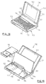
- FIG. 18 An example of portable computer is shown in Fig. 18, in which portable computer 100 has relatively thin body 110 and cover 120, which is coupled to body 110 so that cover 120 can be opened and closed.
- Cover 120 has shallow case 121. At the bottom of case 121 a pair of cylindrical protrusions 122 is formed integrally with the case. With the pair of protrusions 122 rotatable supported with respect to the body, cover 120 is hinged on body 110, allowing cover 120 to be opened or closed with respect to body 110 with an axis of protrusions 122. In the central portion of the open side, i.e. back side, of the cover, liquid crystal display or LCD123 is provided as a display means of the personal computer (hereinafter the cover is generically called LCD120).
- LCD120 liquid crystal display or LCD123
- Body 110 has a shallow case 111 to which support plate 112 of a given width is attached to cover the rear portion of the upper opening of case 111.
- keyboard 113 is placed as an input means of the personal computer.
- a pair of tongue protrusions 114 is formed integrally with keyboard 113. With the pair of protrusions 114 supported axially with the front edge of support plate 112, keyboard 113 is hinged on plate 112. This allows keyboard 113 to be opened or closed with respect to case 111 with an axis of protrusions 114, and the interior of case 111 is exposed when keyboard 113 is opened.
- Opening or closing of LCD120 with respect to body 110 and that of keyboard 113 with respect to case 111 is accomplished by two step operation on open/close control 115 provided on a side of case 111. Since closing LCD120 or opening keyboard 113 will disable computer 100, mechanical operations such as LCD close and keyboard open are electrically converted into CPU interrupt factors.
- Fig. 19 shows the exposed interior of case 111 with keyboard 113 being opened.
- partition 116 is provided to separate the front portion of case 111 from its rear portion.
- Partition 116 may be formed of a thin metal plate by a bending process.
- internal circuits (not shown) of the personal computer including CPU, ROM, RAM and system bus.
- the larger space in front of partition 116 is provided to accommodate expansion devices, such as floppy disk drive (FDD) pack 117 and hard disk drive (HDD) pack 119 and battery pack 118.
- FDD floppy disk drive
- HDD hard disk drive
- battery pack 118 Provided on a side of partition 116 are connectors (not shown) which comply with respective standards for the internal circuits of portable computer 100 to electrically connect these packs with the circuits.
- FDD pack 117 or HDD pack 118 be used exchangeable with other detachable expansion devices.
- FDD pack 117 could be removed from the space in the front portion of case 111 to substitute CDROM drive pack 50.
- CDROM Compact Disk Read Only Memory
- CDROM Compact Disk Read Only Memory
- CDROM has been used to record a great quantity of information such as text data and program data, as well as audio and image data (including pictures, animation and computer graphics).
- Power save is "Suspend", which is to be powered down to almost all portions except main memory for power save when a predetermined state occurs in which an I/O device activity has not been detected for a certain period of time or closing of an LCD (cover) is detected.
- the data necessary for restarting a task such as the hardware context information including I/O configuration and CPU status and the contents of VRAM, is saved in main memory.
- the operation for restarting power supply to exit from the suspend mode for recovery is called “Resume”.
- the resume mode the data previously saved in main memory is restored to each component to enable a task to be restarted from the same point as that of powered down.
- This series of power management operations is actually executed by a program such as those which is called PM code (PMC) or Advanced PM (APM), which is a trademark of Astek International.
- PM code PM code
- API Advanced PM
- One challenge encountered in developing a power management technique is how can a task be resumed quickly and from precisely the same point of execution as of interruption upon recovery from the power save mode such as suspend.
- the portable computer body (hereinafter called host) saves the system information which was present immediately before suspend, such as the hardware context information including register values of each chip and the contents of VRAM, in main memory to preserve the "same point of execution" for the host.
- system information such as the hardware context information including register values of each chip and the contents of VRAM
- the host does not consider the status of the expansion device, but consider only itself, that is, whether it has preserved the "same point of execution" to effect powered down.
- the expansion device can be divided into the one which has no CPU, e.g. floppy disk drive or FDD, and the other which has a build in CPU, e.g. hard disk or HDD and CDROM drive. Operation of the former type is controlled by a controller circuit provided within the host, such as floppy disk controller or FDC. In such cases, the host could preserve the status of FDD immediately before transition to suspend, i.e., the "same point of execution", by managing FDC.
- a controller circuit provided within the host, such as floppy disk controller or FDC.
- the host could preserve the status of FDD immediately before transition to suspend, i.e., the "same point of execution", by managing FDC.
- This type of expansion device includes ROM for storing various types of firmware and RAM as working area of CPU.
- the host operating system or OS does not directly control the expansion device, but only issues an instruction in a form of command to the CPU of the expansion device.
- the CPU of the expansion device interprets the command from the host in accordance with the firmware in ROM and performs actual tasks by using RAM as working area.
- the host OS is not required to directly control all components within the expansion device, and typically has not such function. In these environments, if the host references only the status of itself to be powered down, operation results, e.g. the contents of RAM, on the expansion device will be lost (i.e., because the host has nothing to do against it!), and the lost contents of storage cannot be recovered even if power is supplied again from the host.
- the RAM at the CDROM drive has recorded various information on the disk being inserted.
- This information includes data allocation information such as Table of Contents or TOC, drive parameters indicating data rates, and audio parameters indicating audio output levels.
- TOC information is necessary for searching recording positions during playback of the disk, and is retained when the disk contents are read into RAM during its insertion until either the disk is removed, or power on reset (POR) is done.
- POR power on reset
- Each value of drive and audio parameters is dynamically updated during processing of commands from the host. However, if power supply is suspended only for the convenience of the host, such data in RAM will be lost.
- the TOC information As with normal Power On Reset (POR), must be read again from the disk.
- the CDROM drive has an average access time of as long as 350 milliseconds, requiring seconds or tens of seconds even for reading the TOC information.
- the compact disk usually manages information for each session. The TOC is provided for every session and recorded in the Lead In at the beginning of each session. The TOC has a size of 512 bytes per session. For the disk which consists of multiple sessions, the time required for reading operation will be longer as the number of TOCs increases.) The time duration from several seconds to tens of seconds is too long for the user to wait, taking a random look at the display.
- the CDROM With its high capacity, the CDROM, among others, is often used for providing long programs such as roll playing game, and the user is likely to close the LCD many times to stop a game until the program ends.
- the problem of the resume mode i.e. restarting a task quickly from the same point of execution, becomes more severe.
- Fig. 1 is a block diagram of part of the hardware organization of a computer system in which the present invention is embodied.
- Fig. 2 is the hardware organization of a CDROM drive in which the present invention is embodied.
- Fig. 3 is a schematic illustration which shows the operation modes of a CDROM drive.
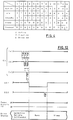
- Fig. 4 is a schematic illustration which shows activities in the CDROM drive in each operation mode.
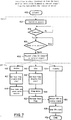
- Fig. 5 is a flow diagram illustrating operation of the CDROM drive during normal power on (POR) by the host.
- Fig. 6 is a flow diagram illustrating operation of the CDROM drive during transition to sleep by an internal timer of drive.
- Fig. 7 is a flow diagram illustrating operation of the CDROM drive during transition to sleep by an instruction of the host.
- Fig. 8 is a flow diagram illustrating operation of the CDROM drive during wake up from sleep.
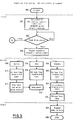
- Fig. 9 is a flow diagram illustrating operation of the CDROM drive during transition from active, idle or standby to suspend mode.
- Fig. 10 is a flow diagram illustrating operation of the CDROM drive during transition from sleep to suspend mode.
- Fig. 11 is a flow diagram illustrating operation of the CDROM drive during resume from suspend mode.
- Fig. 12 illustrates operation of host control and drive status signals when a sleep request by the host control signal causes transition from active, idle or standby to sleep mode.
- Fig. 13 illustrates operation of host control and drive status signals during wake up from sleep.
- Fig. 14 illustrates operation of host control and drive status signals when a suspend request by the host control signal causes transition from active, idle or standby to suspend mode.
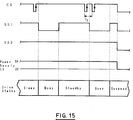
- Fig. 15 illustrates operation of host control and drive status signals during transition from sleep to suspend mode.
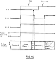
- Fig. 16 illustrates operation of host control and drive status signals during resume from suspend mode.
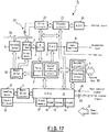
- Fig. 17 is the hardware configuration of a magneto optical disk drive.
- Fig. 18 is an isometric view of a portable computer, and particularly illustrating a usable state with LCD opened.
- Fig. 19 is an isometric view of the portable computer, and particularly illustrating a state in which the case interior is exposed with LCD and the keyboard opened.
- main CPU70 is electrically connected with each unit within the system via system bus 80 so that it controls the operation of the whole system 100.
- Sub CPU60 is provided to support main CPU70 in power management.
- main CPU70, sub CPU60 and system bus 80 should be considered to make up a host.
- CDROM drive (hereinafter also referred to as drive) 50 is connected to main CPU70 through system bus 80 so that it can send to or receive commands from the host.
- Drive 50 is also connected with sub CPU60 through host Control Signal (hereinafter also referred to as CS) 19 and two drive Status Signals (also called SS1 and SS2) 20. The function of signals 19 and 20 will be later described.
- CS host Control Signal
- SS1 and SS2 drive Status Signals
- expansion devices such as FDD and HDD.
- main CPU70 is interrupted to enter the suspend mode.
- a suspend request is raised under control of PM code (PMC) 71.
- PMC PM code
- main CPU70 requests suspend from drive 50 by using a command via system bus 80.
- a suspend request arises under control of APM61.
- sub CPU60 requests suspend from CPU10 in drive 50 via host control signal 19. (The transfer of a suspend request using a host control signal will be described later.)
- PMC71 can be the one which is loaded from system ROM (not shown) during POR and can be the other which is incorporated in the operating system (OS). What is important in the present embodiment, however, is not the operation of power management itself by PMC or APM at the host, but that a suspend request is made by the host to drive 50 in a form of either command or control signal.
- Fig. 2 is a detailed block diagram illustrating the hardware organization of CDROM drive 50 shown in Fig. 1. It should be understood by the following description that the present invention is embodied by using CDROM drive 50.
- Disk (CD) 21 as a storage medium is rotatable mounted onto spindle motor 5. Beneath the surface of disk 21 is located Pick Up Head 1. Motor drive circuit 4 controls the rotation of spindle motor 5 so that the track of disk 21 rotates at a constant linear velocity (CLV) with respect to pick up head 1.
- CLV constant linear velocity
- Pick up head 1 is used for read data using the output of laser to disk 21 and reception of reflected light, and is mounted onto slider motor 6 which is movable in the radial direction of disk 21.
- the output signal from pick up head 1 is input to servo circuit/digital signal processing circuit 3 via RF amplifier 2 for both position control of pick up head 1 and data processing.
- a control system which is made up of servo circuit 3 and motor drive circuit 4 controls synchronous driving of spindle motor 5 and slider motor 6 based on that output signal to enable pick up head 1 to access disk 21.
- Pick up head 1 is supported by a two axis device (not shown) which is capable of precision driving and focus and tracking adjustable.
- the output signal is processed by digital signal processing circuit (DSP) 3.
- DSP digital signal processing circuit
- DAC digital/analog converter circuit
- the signal is output via DAC7 and audio amplifier circuit 8.
- decoder circuit 9 decodes the signal to send it to system bus 80.
- the servo circuit and DSP are shown with identical reference numeral 3, and may be of the same chip or of separate chips.
- a tray (not shown) for mechanically mounting disk 21 is coupled with loading motor 12 in a power transferrable manner.
- Motor drive circuit 11 controls loading motor 12 in response to a signal from eject button 18 which is used to indicate tray open or close operation or a request from CPU10 (or request from the host via CPU10), thus allowing replacement of disk 21.
- CPU10 is a controller means for controlling the operation of each unit within CDROM drive 50.
- CPU10 includes clock 14 for synchronizing operations, ROM16, RAM15 and Electrically Erasable Programmable ROM (EEPROM) 17.
- EEPROM Electrically Erasable Programmable ROM
- ROM16 is a read only memory with its write data determined during manufacture and is used to store various types of firmware.
- the actual firmware to be stored is used for self test performed by drive 50 during start up (POR), command processing for interpreting commands sent from the host (also called host command), checking drive status such as disk in/out and tray open/close, or mechanical control for controlling the drive mechanism such as tray eject.
- RAM15 is first data saving means used by CPU10 as working area and, as described in the introduction above, is used to store various information on the disk 21 being inserted (e.g. allocation information such as TOC, drive parameters indicating data rates, audio parameters indicating audio output levels).
- allocation information such as TOC, drive parameters indicating data rates, audio parameters indicating audio output levels.
- DRAM Dynamic RAM
- SRAM Static RAM
- SRAM is preferred (the reason of which will be described later).
- EEPROM17 is a write-enable non-volatile semiconductor memory and acts as second data saving means, details of which described below.
- Interface circuit 9 is used to control the flow of data between the host and drive 50 and includes a control register, command register, status register, error register and data register.
- the status register includes a field for retaining the current operation mode of drive 50 (operation modes of drive 50 will be described in section C) and a Busy Flag for presenting an Activity of drive 50 to the host.
- the activity of drive 50 can be a Ready state in which a host command can be executed immediately or a Busy state in which no host command can be accepted due to processing of a task.
- the host OS can recognize the status of drive 50 by polling this status register.
- Interface and decoding circuits are shown in Fig. 2 with identical reference numeral 9, and may be configured with the same chip or separate chips.
- communications between CPU10 of drive 50 and the host are performed with commands send or received via interface circuit 9, and also with host control signal 19 and drive status signal 20.
- Host control signal 19 is a signal used by the host to communicate its intention to drive 50 and provided for two purposes in this embodiment. One is to send a request from the host for changing operation mode. Another is to initiate hardware interrupt to CPU10 while clock 14 is in halted. As described in section C, CDROM drive 50 can enter an operation mode of sleep or suspend where clock 14 of CPU10 is in a halt state.
- Halted clock 14 causes interface circuit 9 to stop and accept no command. Therefore, interruption of CPU 10 by host control signal 19 activates clock 14.
- drive status signal 20 is a signal used by drive 50 to communicate its intention to the host, and consists of two signal lines SS1 and SS2, as described above.
- SS1 indicates the activity of drive 50 with a High or Low level of signal.
- SS2 is used to notify the host that drive 50 moves voluntarily from active, idle or standby to sleep mode (see section D.2).
- drive 50 is supplied with power from the host, as shown with an arrow of reference numeral 13, detailed power lines are not shown. It should be noted, however, that turning on or off this power supply 13 is caused by normal power on (POR) or power off at the host and also dependent upon suspend/resume operation.
- POR power on
- CDROM drive 50 has five operation modes: Active, Idle, Standby, Sleep and Suspend.
- Fig. 3 schematically shows each operation mode and transitions between them. Transition between each mode is triggered by an internal timer of drive 50, a request by a host command or host control signal, application of power from the host for resume, or normal application or suspension of power (POR) by the host.
- each transition is represented by an arrow indicating a trigger. The procedure of transition to each operation mode depends on its trigger and will be described in detail in section D.
- each mechanism and electrical circuit within drive 50 varies between operation modes, and their relationship is shown in Fig. 4.
- column headings indicate components of drive 50 (the numbers in column headings correspond to reference numerals in Fig. 2), and row headings indicate operation modes.
- Characters A (Active), I (Inactive) and D (Disabled) in each column of the table denote the activity state in the corresponding operation mode of each component, and the activity level descends in this order; A, I and D.
- CDROM drive 50 may enter the other modes not with a host command but with host control signal 19.
- the intention of the host may communicate only with host control signal 19 because the halt of clock 14 of CPU10 inhibits reception of the host command.
- host control signal (CS) 19 acts in cooperation with drive status signals 20 (SS1 and SS2). This section will describe the relationship between each signal line and the operation of drive 50 with reference to Figs. 12 to 16. In each timing diagram shown in Figs.
- the first line denotes the signal level of host control signal (CS) 19
- the second line the signal level of drive status signal SS1
- the third line the signal level of drive status signal SS2
- the fourth line the voltage level of supply power from the host and the fifth line the operation mode of drive 50.
- the preferred embodiment of the present invention uses a CDROM drive.
- magneto optical disks which are similar to CDROM drives in structure and effects, also have problems which can be addressed by the present invention. This section will briefly describe that the present invention can also be practised in relation to magneto optical disk drives.
- Fig. 17 shows the hardware configuration of magneto optical disk drive 51 in which the present invention is practised. Identical reference numbers indicate similar components to those shown in Fig. 2.
- Magneto optical disk drive 51 differs from CDROM drive 50 in that drive 51 further includes magnetic coil 25 for write operation to magneto optical (MO) disk 26, drive circuit 22 for driving magnetic coil 25, analog/digital converter circuit (ADC) 24 for converting analog input into digital signals and encoder circuit 23 for encoding signals.
- MO magneto optical
- ADC analog/digital converter circuit
- an expansion device detachably installed into a computer system (host) and capable of quickly and exactly in response to a series of operations for power management at the host. Furthermore, it is possible to provide an environment for a portable computer system wherein the expansion device itself saves the information which is required during resume operation and cannot be managed at the host when the suspend mode is entered, thereby allowing a task to be restarted quickly and from precisely the same point of execution during resume.
Landscapes
- Engineering & Computer Science (AREA)
- Theoretical Computer Science (AREA)
- Physics & Mathematics (AREA)
- General Engineering & Computer Science (AREA)
- Computer Hardware Design (AREA)
- General Physics & Mathematics (AREA)
- Human Computer Interaction (AREA)
- Mathematical Physics (AREA)
- Power Sources (AREA)
- Techniques For Improving Reliability Of Storages (AREA)
Applications Claiming Priority (3)
| Application Number | Priority Date | Filing Date | Title |
|---|---|---|---|
| JP88674/94 | 1994-04-26 | ||
| JP8867494 | 1994-04-26 | ||
| JP6088674A JP2986048B2 (ja) | 1994-04-26 | 1994-04-26 | コンピュータ・システムに装着可能な拡張デバイス、拡張デバイスの制御方法及び拡張デバイスを有するコンピュータ・システムの制御方法 |
Publications (3)
| Publication Number | Publication Date |
|---|---|
| EP0679983A2 true EP0679983A2 (fr) | 1995-11-02 |
| EP0679983A3 EP0679983A3 (fr) | 1998-12-09 |
| EP0679983B1 EP0679983B1 (fr) | 2003-11-12 |
Family
ID=13949378
Family Applications (1)
| Application Number | Title | Priority Date | Filing Date |
|---|---|---|---|
| EP95302560A Expired - Lifetime EP0679983B1 (fr) | 1994-04-26 | 1995-04-18 | Dispositif d'extension avec fonction d'arrêt/reprise |
Country Status (7)
| Country | Link |
|---|---|
| US (1) | US5659762A (fr) |
| EP (1) | EP0679983B1 (fr) |
| JP (1) | JP2986048B2 (fr) |
| KR (1) | KR0184626B1 (fr) |
| CN (1) | CN1109280C (fr) |
| DE (1) | DE69532097T2 (fr) |
| SG (1) | SG42454A1 (fr) |
Cited By (8)
| Publication number | Priority date | Publication date | Assignee | Title |
|---|---|---|---|---|
| EP1039740A3 (fr) * | 1999-03-26 | 2002-01-23 | SANYO ELECTRIC Co., Ltd. | Caméra électronique |
| EP1046979A4 (fr) * | 1998-11-09 | 2002-04-24 | Seiko Epson Corp | Dispositif d'interface, procede de commande de dispositif d'interface, et dispositif d'enregistrement d'informations |
| EP1158398A3 (fr) * | 2000-05-26 | 2003-07-23 | Ricoh Company, Ltd. | Appareil d'enregistrement d'informations, système d'enregistrement d'informations et support d'enregistrement d'informations |
| EP1191425A3 (fr) * | 2000-08-29 | 2003-10-01 | Sony Corporation | Appareil électronique couplable à un système hôte et procédés de commande de sa consommation d'énergie |
| WO2004057475A1 (fr) * | 2002-12-20 | 2004-07-08 | Philips Intellectual Property & Standards Gmbh | Module pour lire un support de donnees |
| WO2003079183A3 (fr) * | 2002-03-12 | 2004-10-21 | Barry Edmund James | Dispositif memoire a logiciel d'applications pour une connexion communicable a un ordinateur hote |
| EP1218882A4 (fr) * | 1999-08-24 | 2009-07-22 | O2Micro Int Ltd | Lecteur de cd-rom a touche de lancement a faible consommation d'energie pour ordinateurs portables |
| CN114158115A (zh) * | 2022-02-10 | 2022-03-08 | 为准(北京)电子科技有限公司 | 一种无线测试设备的供电管理方法、装置及系统 |
Families Citing this family (45)
| Publication number | Priority date | Publication date | Assignee | Title |
|---|---|---|---|---|
| KR0139985B1 (ko) * | 1995-01-06 | 1998-07-01 | 김광호 | 옵션 카드의 하이버네이션 시스템 |
| KR100186349B1 (en) * | 1996-12-17 | 1999-04-15 | Lg Ind Systems Co Ltd | Power failure compensation method of plc and plc having function of power failure compensation |
| JP3253881B2 (ja) * | 1997-01-06 | 2002-02-04 | 株式会社東芝 | コンピュータシステムおよびそのシステムにおけるハイバネーション制御方法 |
| KR19980073522A (ko) * | 1997-03-15 | 1998-11-05 | 김광호 | 파워다운모드를 지원하는 반도체 메모리 장치와 이를 구비한 컴퓨터 시스템 및 이의 제어방법 |
| US6006285A (en) * | 1997-04-30 | 1999-12-21 | Compaq Computer Corporation | Computer system capable of playing audio CDs in a CD-ROM drive independent of an operating system |
| KR100502400B1 (ko) * | 1997-07-31 | 2005-11-03 | 삼성전자주식회사 | 복수의주변저장장치선택제어기능을갖는컴퓨터및그선택제어방법 |
| US6131167A (en) * | 1997-12-31 | 2000-10-10 | Intel Corporation | Method and apparatus to reduce power consumption on a bus |
| US6256751B1 (en) | 1998-10-29 | 2001-07-03 | International Business Machines Corporation | Restoring checkpointed processes without restoring attributes of external data referenced by the processes |
| US6799242B1 (en) * | 1999-03-05 | 2004-09-28 | Sanyo Electric Co., Ltd. | Optical disc player with sleep mode |
| JP2000298917A (ja) | 1999-04-12 | 2000-10-24 | Fujitsu Ltd | 記憶装置 |
| JP3705957B2 (ja) | 1999-06-11 | 2005-10-12 | ヒタチグローバルストレージテクノロジーズネザーランドビーブイ | ディスクストレージ装置における不良セクタ処理方法及びディスクストレージ装置 |
| JP2003015784A (ja) * | 2001-07-02 | 2003-01-17 | Yamaha Corp | サウンドユニット |
| JP3692086B2 (ja) * | 2002-03-12 | 2005-09-07 | 株式会社東芝 | ディスク記憶装置におけるスピンドルモータの駆動方法 |
| KR100505638B1 (ko) * | 2002-08-28 | 2005-08-03 | 삼성전자주식회사 | 워킹 콘텍스트 저장 및 복구 장치 및 방법 |
| JP3767818B2 (ja) * | 2002-10-28 | 2006-04-19 | 株式会社サスライト | 着脱式デバイス及びプログラムの起動方法 |
| US7340607B2 (en) * | 2003-02-04 | 2008-03-04 | Eastman Kodak Company | Preservation system for digitally created and digitally signed documents |
| US20040250147A1 (en) * | 2003-06-03 | 2004-12-09 | Christopher Chang | Uninterrupted system operation |
| JP4371739B2 (ja) | 2003-09-02 | 2009-11-25 | 株式会社東芝 | シリアルataインタフェースを持つ電子機器及びシリアルataバスのパワーセーブ方法 |
| US7231532B2 (en) * | 2003-09-30 | 2007-06-12 | Intel Corporation | Generating notifications by powered-down devices |
| TWI242133B (en) * | 2003-12-02 | 2005-10-21 | Via Tech Inc | Interrupt signal control method |
| US20050138441A1 (en) * | 2003-12-19 | 2005-06-23 | Huffman Amber D. | Power management without interrupt latency |
| JP4706956B2 (ja) * | 2005-01-31 | 2011-06-22 | セイコーエプソン株式会社 | 情報端末、及び、電池残量算出方法 |
| JP4293948B2 (ja) * | 2004-07-09 | 2009-07-08 | 富士通株式会社 | ディスク装置およびディスク装置の制御方法 |
| US7161758B2 (en) * | 2004-11-12 | 2007-01-09 | Lenovo (Singapore) Pte. Ltd. | Hard drive protection override |
| JP2007004474A (ja) * | 2005-06-23 | 2007-01-11 | Fuji Xerox Co Ltd | 情報処理装置及び情報処理方法 |
| US8004617B2 (en) * | 2006-08-30 | 2011-08-23 | Ati Technologies Ulc | Stand-by mode transitioning |
| TWI335590B (en) * | 2006-11-30 | 2011-01-01 | Quanta Storage Inc | Recovery method for recording a write-once disc |
| TWI340348B (en) * | 2007-11-16 | 2011-04-11 | Asustek Comp Inc | Electronic device and method for resuming from suspend-to-ram state thereof |
| JPWO2009101804A1 (ja) * | 2008-02-13 | 2011-06-09 | パナソニック株式会社 | 省電力システム |
| US20100146169A1 (en) * | 2008-12-05 | 2010-06-10 | Nuvoton Technology Corporation | Bus-handling |
| JP2010257354A (ja) * | 2009-04-28 | 2010-11-11 | Alps Electric Co Ltd | デバイス認識方法 |
| KR101596222B1 (ko) * | 2009-08-25 | 2016-02-23 | 삼성전자주식회사 | 영상 재생 장치의 부팅을 제어하는 방법 및 그 장치 |
| US8769338B1 (en) * | 2010-03-24 | 2014-07-01 | Qualcomm Incorporated | Saving and restoring states through low power mode |
| US8527792B2 (en) * | 2011-05-13 | 2013-09-03 | Synology Incorporated | Power saving method and apparatus thereof |
| US8671299B2 (en) | 2011-05-26 | 2014-03-11 | Google Inc. | Delaying the initiation of transitioning to a lower power mode by placing a computer system into an intermediate power mode between a normal power mode and the lower power mode |
| JP5558453B2 (ja) * | 2011-11-16 | 2014-07-23 | 株式会社東芝 | デバイス状態制御方法および情報処理装置 |
| CN103389785A (zh) * | 2012-05-10 | 2013-11-13 | 飞利浦建兴数位科技股份有限公司 | 光驱与计算机系统及其相关控制方法 |
| US9207749B2 (en) * | 2012-08-28 | 2015-12-08 | Intel Corporation | Mechanism for facilitating efficient operations paths for storage devices in computing systems |
| JP6110122B2 (ja) * | 2012-12-07 | 2017-04-05 | シナプティクス・ジャパン合同会社 | 集積回路装置、パネル表示装置及び表示パネルドライバ |
| JP6135033B2 (ja) * | 2013-03-04 | 2017-05-31 | レシップホールディングス株式会社 | 電源制御装置 |
| JP2014235544A (ja) * | 2013-05-31 | 2014-12-15 | 株式会社東芝 | 電子機器および入力制御方法 |
| TW201742063A (zh) * | 2016-05-30 | 2017-12-01 | 慧榮科技股份有限公司 | 資料儲存方法及發生電源中斷事件後之系統初始化之方法 |
| US10345885B2 (en) * | 2016-09-27 | 2019-07-09 | Intel Corporation | Power control of a memory device through a sideband channel of a memory bus |
| DE102016015512A1 (de) * | 2016-12-23 | 2018-06-28 | Bayerische Motoren Werke Ag | Elektrisches Energiemanagement eines Bordsystems eines Kraftfahrzeuges |
| WO2023024056A1 (fr) * | 2021-08-27 | 2023-03-02 | Yangtze Memory Technologies Co., Ltd. | Dispositif de mémoire et opération de programme associée |
Family Cites Families (14)
| Publication number | Priority date | Publication date | Assignee | Title |
|---|---|---|---|---|
| US5175842A (en) * | 1988-05-31 | 1992-12-29 | Kabushiki Kaisha Toshiba | Data storage control system capable of reading data immediately after powered on |
| JP2609542B2 (ja) * | 1988-10-04 | 1997-05-14 | パイオニア株式会社 | ディスクプレーヤ |
| US5167024A (en) * | 1989-09-08 | 1992-11-24 | Apple Computer, Inc. | Power management for a laptop computer with slow and sleep modes |
| JP2877378B2 (ja) * | 1989-09-29 | 1999-03-31 | 株式会社東芝 | パーソナルコンピュータ |
| JP2893758B2 (ja) * | 1989-10-25 | 1999-05-24 | 日本電気株式会社 | 光ディスク装置 |
| JPH03171310A (ja) * | 1989-11-30 | 1991-07-24 | Toshiba Corp | パーソナルコンピュータ |
| US5193176A (en) * | 1990-10-17 | 1993-03-09 | Powercard Supply C.A. | Computer work saving during power interruption |
| GB2256735B (en) * | 1991-06-12 | 1995-06-21 | Intel Corp | Non-volatile disk cache |
| JP3096489B2 (ja) * | 1991-07-09 | 2000-10-10 | 富士通株式会社 | ディスク装置 |
| US5261072A (en) * | 1991-10-31 | 1993-11-09 | Tandy Corporation | Compact disk data transfer system using cache memory |
| US5345347A (en) * | 1992-02-18 | 1994-09-06 | Western Digital Corporation | Disk drive with reduced power modes |
| US5323291A (en) * | 1992-10-15 | 1994-06-21 | Apple Computer, Inc. | Portable computer and docking station having an electromechanical docking/undocking mechanism and a plurality of cooperatively interacting failsafe mechanisms |
| US5313596A (en) * | 1993-01-05 | 1994-05-17 | Dell Usa Lp | Motorized portable computer/expansion chassis docking system |
| US5452277A (en) * | 1993-12-30 | 1995-09-19 | International Business Machines Corporation | Adaptive system for optimizing disk drive power consumption |
-
1994
- 1994-04-26 JP JP6088674A patent/JP2986048B2/ja not_active Expired - Lifetime
-
1995
- 1995-03-31 KR KR1019950007161A patent/KR0184626B1/ko not_active Expired - Lifetime
- 1995-04-07 CN CN95104002A patent/CN1109280C/zh not_active Expired - Lifetime
- 1995-04-11 SG SG1995000244A patent/SG42454A1/en unknown
- 1995-04-17 US US08/423,115 patent/US5659762A/en not_active Expired - Lifetime
- 1995-04-18 EP EP95302560A patent/EP0679983B1/fr not_active Expired - Lifetime
- 1995-04-18 DE DE69532097T patent/DE69532097T2/de not_active Expired - Fee Related
Cited By (14)
| Publication number | Priority date | Publication date | Assignee | Title |
|---|---|---|---|---|
| EP1046979A4 (fr) * | 1998-11-09 | 2002-04-24 | Seiko Epson Corp | Dispositif d'interface, procede de commande de dispositif d'interface, et dispositif d'enregistrement d'informations |
| US6742130B1 (en) | 1998-11-09 | 2004-05-25 | Seiko Epson Corporation | Interface apparatus, control method therefor, and information recording medium |
| EP1039740A3 (fr) * | 1999-03-26 | 2002-01-23 | SANYO ELECTRIC Co., Ltd. | Caméra électronique |
| US6744465B1 (en) | 1999-03-26 | 2004-06-01 | Sanyo Electric Co., Ltd. | Digital camera with nonvolatile memory for storing image management data |
| EP1218882A4 (fr) * | 1999-08-24 | 2009-07-22 | O2Micro Int Ltd | Lecteur de cd-rom a touche de lancement a faible consommation d'energie pour ordinateurs portables |
| EP1158398A3 (fr) * | 2000-05-26 | 2003-07-23 | Ricoh Company, Ltd. | Appareil d'enregistrement d'informations, système d'enregistrement d'informations et support d'enregistrement d'informations |
| US6731577B2 (en) | 2000-05-26 | 2004-05-04 | Ricoh Company, Ltd. | Information recording apparatus, information recording system and information recording medium |
| EP1191425A3 (fr) * | 2000-08-29 | 2003-10-01 | Sony Corporation | Appareil électronique couplable à un système hôte et procédés de commande de sa consommation d'énergie |
| US6971035B2 (en) | 2000-08-29 | 2005-11-29 | Sony Corporation | Method and system for reducing power consumption of a multi-function electronic apparatus that is adapted to receive power from a host system |
| WO2003079183A3 (fr) * | 2002-03-12 | 2004-10-21 | Barry Edmund James | Dispositif memoire a logiciel d'applications pour une connexion communicable a un ordinateur hote |
| US7051157B2 (en) | 2002-03-12 | 2006-05-23 | Barry Edmund James | Memory device with applications software for releasable connection to a host computer |
| WO2004057475A1 (fr) * | 2002-12-20 | 2004-07-08 | Philips Intellectual Property & Standards Gmbh | Module pour lire un support de donnees |
| CN114158115A (zh) * | 2022-02-10 | 2022-03-08 | 为准(北京)电子科技有限公司 | 一种无线测试设备的供电管理方法、装置及系统 |
| CN114158115B (zh) * | 2022-02-10 | 2022-04-19 | 为准(北京)电子科技有限公司 | 一种无线测试设备的供电管理方法、装置及系统 |
Also Published As
| Publication number | Publication date |
|---|---|
| EP0679983A3 (fr) | 1998-12-09 |
| CN1109280C (zh) | 2003-05-21 |
| JPH07295672A (ja) | 1995-11-10 |
| US5659762A (en) | 1997-08-19 |
| DE69532097T2 (de) | 2004-08-26 |
| CN1120688A (zh) | 1996-04-17 |
| SG42454A1 (en) | 1997-08-15 |
| KR0184626B1 (ko) | 1999-05-15 |
| JP2986048B2 (ja) | 1999-12-06 |
| DE69532097D1 (de) | 2003-12-18 |
| KR950029912A (ko) | 1995-11-24 |
| EP0679983B1 (fr) | 2003-11-12 |
Similar Documents
| Publication | Publication Date | Title |
|---|---|---|
| EP0679983B1 (fr) | Dispositif d'extension avec fonction d'arrêt/reprise | |
| US5964878A (en) | Method for controlling operation of optical disk drive in power saving mode | |
| KR0174711B1 (ko) | 하드디스크 캐시의 제어방법 | |
| EP0945778B1 (fr) | Lecteur de CD-ROM à faible consommation d' energie pour ordinateur portable | |
| US5898880A (en) | Power saving apparatus for hard disk drive and method of controlling the same | |
| EP1440444B1 (fr) | Lecteur multimedia a capacite de lecture instantanee | |
| US5345347A (en) | Disk drive with reduced power modes | |
| US7002884B2 (en) | Intermediate power down mode for a rotatable media data storage device | |
| US6865621B2 (en) | Activating an operating system of a computer in response to an operation of power switch of a medium drive without turned on a main switch of the computer | |
| JP2007506223A (ja) | 電子デバイス用の低電力メディアプレーヤ | |
| KR100700224B1 (ko) | 오디오 파일을 플레이하기 위한 컴퓨터 시스템용 기계 판독형 매체 | |
| CN101625624B (zh) | 一种基于嵌入式系统的sata硬盘管理方法 | |
| US5761519A (en) | Portable computer having a removable medium drive and a resume setting function | |
| US6134069A (en) | Method of power saving in a disk drive apparatus with head unloading and spin reduction | |
| JPH04205963A (ja) | ディスク装置 | |
| US20060259795A1 (en) | Portable computer and data backup method thereof | |
| US7457975B2 (en) | Information processing apparatus with a function for low-power operation by controlling a power supply to a recording section of a recording medium and a computer individually | |
| JP2001283503A (ja) | 磁気記憶装置のヘッドアンロードの制御方法及び磁気記憶装置 | |
| JP3487341B2 (ja) | データ変換装置 | |
| JP4770520B2 (ja) | ドライブコントローラ及び光ディスク装置 | |
| WO2001082301A2 (fr) | Gestion de puissance pour unites de disques optiques | |
| KR20060040507A (ko) | 스핀들 모터 기동 전류 제어 방법 및 이를 이용한 디스크드라이브 | |
| JP3702928B2 (ja) | Cd−romドライブの動作制御方法 | |
| JP2003256087A (ja) | 節電モードにより音楽記録媒体を再生するコンピュータシステム | |
| JP2010272162A (ja) | 情報処理装置、メディアドライブおよび情報処理装置におけるメディアデータキャッシング管理方法 |
Legal Events
| Date | Code | Title | Description |
|---|---|---|---|
| PUAI | Public reference made under article 153(3) epc to a published international application that has entered the european phase |
Free format text: ORIGINAL CODE: 0009012 |
|
| AK | Designated contracting states |
Kind code of ref document: A2 Designated state(s): DE FR GB |
|
| 17P | Request for examination filed |
Effective date: 19960213 |
|
| PUAL | Search report despatched |
Free format text: ORIGINAL CODE: 0009013 |
|
| AK | Designated contracting states |
Kind code of ref document: A3 Designated state(s): DE FR GB |
|
| GRAH | Despatch of communication of intention to grant a patent |
Free format text: ORIGINAL CODE: EPIDOS IGRA |
|
| GRAS | Grant fee paid |
Free format text: ORIGINAL CODE: EPIDOSNIGR3 |
|
| GRAA | (expected) grant |
Free format text: ORIGINAL CODE: 0009210 |
|
| AK | Designated contracting states |
Kind code of ref document: B1 Designated state(s): DE FR GB |
|
| REG | Reference to a national code |
Ref country code: GB Ref legal event code: FG4D |
|
| REF | Corresponds to: |
Ref document number: 69532097 Country of ref document: DE Date of ref document: 20031218 Kind code of ref document: P |
|
| ET | Fr: translation filed | ||
| PLBE | No opposition filed within time limit |
Free format text: ORIGINAL CODE: 0009261 |
|
| STAA | Information on the status of an ep patent application or granted ep patent |
Free format text: STATUS: NO OPPOSITION FILED WITHIN TIME LIMIT |
|
| 26N | No opposition filed |
Effective date: 20040813 |
|
| PGFP | Annual fee paid to national office [announced via postgrant information from national office to epo] |
Ref country code: FR Payment date: 20050420 Year of fee payment: 11 |
|
| REG | Reference to a national code |
Ref country code: GB Ref legal event code: 732E |
|
| REG | Reference to a national code |
Ref country code: FR Ref legal event code: TP |
|
| REG | Reference to a national code |
Ref country code: FR Ref legal event code: ST Effective date: 20061230 |
|
| PG25 | Lapsed in a contracting state [announced via postgrant information from national office to epo] |
Ref country code: FR Free format text: LAPSE BECAUSE OF NON-PAYMENT OF DUE FEES Effective date: 20060502 |
|
| PGFP | Annual fee paid to national office [announced via postgrant information from national office to epo] |
Ref country code: DE Payment date: 20080424 Year of fee payment: 14 |
|
| PGFP | Annual fee paid to national office [announced via postgrant information from national office to epo] |
Ref country code: GB Payment date: 20080423 Year of fee payment: 14 |
|
| GBPC | Gb: european patent ceased through non-payment of renewal fee |
Effective date: 20090418 |
|
| PG25 | Lapsed in a contracting state [announced via postgrant information from national office to epo] |
Ref country code: DE Free format text: LAPSE BECAUSE OF NON-PAYMENT OF DUE FEES Effective date: 20091103 |
|
| PG25 | Lapsed in a contracting state [announced via postgrant information from national office to epo] |
Ref country code: GB Free format text: LAPSE BECAUSE OF NON-PAYMENT OF DUE FEES Effective date: 20090418 |