EP0680124B1 - Dübel zur Wandbefestigung und zusammenwerkende Mutter - Google Patents
Dübel zur Wandbefestigung und zusammenwerkende Mutter Download PDFInfo
- Publication number
- EP0680124B1 EP0680124B1 EP19950410027 EP95410027A EP0680124B1 EP 0680124 B1 EP0680124 B1 EP 0680124B1 EP 19950410027 EP19950410027 EP 19950410027 EP 95410027 A EP95410027 A EP 95410027A EP 0680124 B1 EP0680124 B1 EP 0680124B1
- Authority
- EP
- European Patent Office
- Prior art keywords
- nut
- plug according
- fixing
- locking part
- wall
- Prior art date
- Legal status (The legal status is an assumption and is not a legal conclusion. Google has not performed a legal analysis and makes no representation as to the accuracy of the status listed.)
- Expired - Lifetime
Links
- 230000008878 coupling Effects 0.000 claims description 6
- 238000010168 coupling process Methods 0.000 claims description 6
- 238000005859 coupling reaction Methods 0.000 claims description 6
- 238000007598 dipping method Methods 0.000 claims 1
- 230000000903 blocking effect Effects 0.000 description 7
- 210000003423 ankle Anatomy 0.000 description 6
- 238000009434 installation Methods 0.000 description 2
- 239000011810 insulating material Substances 0.000 description 2
- 238000000034 method Methods 0.000 description 2
- 238000000465 moulding Methods 0.000 description 2
- 210000002445 nipple Anatomy 0.000 description 2
- 230000002093 peripheral effect Effects 0.000 description 2
- 241001080024 Telles Species 0.000 description 1
- 238000006073 displacement reaction Methods 0.000 description 1
- 238000004519 manufacturing process Methods 0.000 description 1
- 238000005192 partition Methods 0.000 description 1
- 239000007787 solid Substances 0.000 description 1
Images

Classifications
-
- H—ELECTRICITY
- H02—GENERATION; CONVERSION OR DISTRIBUTION OF ELECTRIC POWER
- H02G—INSTALLATION OF ELECTRIC CABLES OR LINES, OR OF COMBINED OPTICAL AND ELECTRIC CABLES OR LINES
- H02G3/00—Installations of electric cables or lines or protective tubing therefor in or on buildings, equivalent structures or vehicles
- H02G3/02—Details
- H02G3/08—Distribution boxes; Connection or junction boxes
- H02G3/088—Dustproof, splashproof, drip-proof, waterproof, or flameproof casings or inlets
-
- F—MECHANICAL ENGINEERING; LIGHTING; HEATING; WEAPONS; BLASTING
- F16—ENGINEERING ELEMENTS AND UNITS; GENERAL MEASURES FOR PRODUCING AND MAINTAINING EFFECTIVE FUNCTIONING OF MACHINES OR INSTALLATIONS; THERMAL INSULATION IN GENERAL
- F16B—DEVICES FOR FASTENING OR SECURING CONSTRUCTIONAL ELEMENTS OR MACHINE PARTS TOGETHER, e.g. NAILS, BOLTS, CIRCLIPS, CLAMPS, CLIPS OR WEDGES; JOINTS OR JOINTING
- F16B35/00—Screw-bolts; Stay-bolts; Screw-threaded studs; Screws; Set screws
- F16B35/04—Screw-bolts; Stay-bolts; Screw-threaded studs; Screws; Set screws with specially-shaped head or shaft in order to fix the bolt on or in an object
- F16B35/06—Specially-shaped heads
Definitions
- the present invention relates to a wall anchor comprising a body of winged anchor and an expansion rod adapted to be engaged in said body to cause expansion and its blocking in position in a suitable opening practiced in a wall.
- This type of plug is commonly used for all kinds of applications, such as fixing plates of insulating materials, fixing clamps for the mounting of electric cables or guide tubes for such cables.
- fixing plates of insulating materials such as fixing plates of insulating materials, fixing clamps for the mounting of electric cables or guide tubes for such cables.
- fixing clamps for fixing of electrical equipment boxes or junction boxes.
- dowels and large head screws we use usually conventional dowels and large head screws to support against the bottom of the boxes or boxes to press them against the walls and keep firmly in the desired position.
- This link has the disadvantage not to guarantee an absolute seal and to be relatively tedious to put in place square.
- Document DE-B-1115332 relates to a device for wall-mounting a box of insulating material. in which the establishment of the box is carried out either by sliding a screw head in a dovetail groove, or by means of a screw embedded in the bottom of the box, either by rotation of the box on the threaded part of a screw. Such a method of attachment does not allow rapid assembly of the box.
- the present invention proposes to overcome these drawbacks by making a dowel for wall mounting as defined in the preamble and which allows rapid fixing and waterproof junction boxes or boxes, especially for switchgear electric.
- said expansion rod comprises means for fixing a housing, in particular for electrical equipment.
- said fixing means comprising a threaded end piece, and a removable blocking member arranged to be mounted on said endpiece to block the housing in position.
- said blocking member comprising a sealed cap.
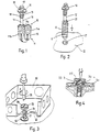
- the pin 10 shown mainly comprises a body 11 and an expansion rod 12 intended to be engaged in this body.
- the body 11 is preferably, but not exclusively, consisting of two half-shells 11a and 11b linked together by a molding residue 11c which forms a joint and which makes it possible to bring the two half-shells facing each other to form a body having a general shape substantially cylindrical and which is provided at its periphery with fins 13 which have a substantially circular shape as shown more particularly Figure 2.
- the expansion rod has the general shape of a nail, pointed at its end to allow its introduction inside the body 11 of the ankle.
- the stem composed of a substantially cylindrical sector 14 having a smooth wall, surmounted a sector 15 of enlarged section compared to that of sector 14, of a disc support 16 and a tip 17 which defines its upper end.
- Sector 15 can be provided with peripheral fins 18 or have a slightly shaped tapered.
- the support disc 16 has a diameter significantly greater than the diameter from other areas of the stem.
- the end piece 17 is in this case threaded and in particular provided with a thread 19 of the quick pitch type.
- the pre-assembled ankle i.e. with a body as it is made after juxtaposition of the two half-shells 11a and 11b and with an expansion rod engaged in a central opening formed inside said body 11, is engaged in a blind hole 21 made in a wall wall 22, a ceiling or any other suitable support.
- the hole 21 generally has a substantially equal diameter to that of the body 11 in such a way that this body can be engaged relatively easily inside this hole.
- the expansion of the ankle and its blocking in position in the hole are obtained when the expansion rod is completely pressed into the opening 20 of the ankle body.
- the expansion rod is pressed into the body of the anchor until the support disc 16 is in contact with the surface of the wall 22 in which the opening 21 has been formed.
- FIG. 3 represents such an installation under the form of an exploded view.
- a housing 30 provided with an opening 31 formed in its bottom 32 is placed on the end piece 17 and on the support disc 16 such so that said tip 17 passes through the opening 31.
- a nut 33 which is in this case in the form of a waterproof cap, is fitted on the part of the end piece 17 which extends towards the inside of the housing 30.
- This nut in the form of cap carries on its upper surface a notch 34 which is arranged to receive the end of a screwdriver 35.
- the end piece 17 and the nut 33 define means for fixing the housing 30 to the ankle previously locked in position in an opening in a wall.
- the end of the expansion rod constitutes a male element on which fits a removable female blocking member, the two elements being arranged to cooperate in order to fix in position for example the bottom of a housing for electrical equipment. It is obvious that this coupling carried out in the example shown as a quick pitch thread can be changed and if necessary replaced by a bayonet type system or similar.
- the nut 33 is equipped with a base latching 33a intended to be clipped onto an annular flange 33b surrounding coaxially the opening 31.
- the nut 33 is then pre-assembled on the bottom of the case 30, and also acts as a waterproof cap when the case is not still attached to the wall. Such pre-assembly of the nut 33 facilitates the installation of the housing 30 on the wall or partition.
- FIGS. 5 and 6 Two variant embodiments are shown in FIGS. 5 and 6.
- the end piece 17 is provided with two lateral pins 40, 41.
- a locking member 42 provided with a central opening in which is fitted the end piece 17, has two grooves 43 and 44, L-shaped, intended for receive the two pins 40 and 41 respectively.
- the positioning of the blocking on the nipples is carried out in two phases: a first phase in which the relative displacement is a translation in such a way that the two pins 40 and 41 can engage in an axial direction in the grooves 43 and 44 and a second phase during which the relative movement is a rotation of such so that the two pins 40 and 41 can engage at the bottom of the two branches lateral of the respective grooves 43 and 44.
- the locking member 42 is in the form of a cap, the upper part of which is provided with a notch 45 allowing the grip with the end of a screwdriver by means of which the operator rotates this locking member.
- FIG. 6 shows an embodiment in which the end piece 17 is provided two L-shaped grooves 50 and 51 and the locking member 52, still in shape cap to ensure the tightness of the connection, has on the face inside of the opening in which the end piece 17 is engaged, two lateral pins 53 and 54 intended to penetrate into grooves 50 and 51.
- the operating principle is substantially that of a system bayonet coupling.
- the grooves can have an appropriate profile, for example in the form of a constriction formed on the lateral branch, so that a anti-recoil blocking of the nipples engaged in these grooves.
Landscapes
- Engineering & Computer Science (AREA)
- General Engineering & Computer Science (AREA)
- Mechanical Engineering (AREA)
- Architecture (AREA)
- Civil Engineering (AREA)
- Structural Engineering (AREA)
- Connector Housings Or Holding Contact Members (AREA)
- Casings For Electric Apparatus (AREA)
- Clamps And Clips (AREA)
- Mounting Components In General For Electric Apparatus (AREA)
- Dowels (AREA)
Claims (7)
- Wandbefestigungsdübel mit einem, mit Zähnen (13) versehenen Dübelkörper (11) sowie einem Spreizbolzen (12), der dazu dient, in den genannten Körper eingeführt zu werden, um die Spreizung sowie die Feststellung in seiner Lage in einer, in einer Mauerwand ausgebildeten geeigneten Bohrung zu bewirken,
dadurch gekennzeichnet, daß der genannte Spreizbolzen (12) Mittel zur Befestigung eines, insbesondere zur Aufnahme eines elektrischen Schaltgeräts dienenden Gehäuses aufweist, wobei die genannten Befestigungsmittel einen Gewindezapfen (17) sowie ein abnehmbares Feststellelement umfassen, das dazu ausgelegt ist, auf dem genannten Zapfen montiert zu werden, um das Gehäuse in seiner Lage festzustellen, und daß das genannte Feststellelement eine dichte Kappe umfaßt. - Dübel nach Anspruch 1, dadurch gekennzeichnet, daß das genannte abnehmbare Feststellelement als Mutter (33) ausgebildet ist, die dazu ausgelegt ist, auf den Zapfen aufgeschraubt zu werden, der ein Schnellbaugewinde zu schnellen Befestigung der Mutter aufweist.
- Dübel nach Anspruch 1, dadurch gekennzeichnet, daß der genannte Zapfen (17) zwei seitliche Nasen (40, 41) und das genannte abnehmbare Feststellelement (42) zwei L-förmige Nuten (43, 44) aufweist, die so ausgelegt sind, daß die beiden Nasen in die beiden genannten Nuten eingeführt werden können, um einen Bajonettverschluß zu bilden.
- Dübel nach Anspruch 1, dadurch gekennzeichnet, daß das genannte abnehmbare Feststellelement (52) zwei seitliche Nasen (53, 54) und der genannte Zapfen (17) zwei L-förmige Nuten (50, 51) aufweist, die so ausgelegt sind, daß die beiden Nasen in die beiden genannten Nuten eingeführt werden können, um einen Bajonettverschluß zu bilden.
- Dübel nach Anspruch 1, dadurch gekennzeichnet, daß der genannte Zapfen (17) des Spreizbolzens (12) durch einen, fest mit dem genannten Bolzen verbundenen Stützkragen (16) begrenzt wird, der einen wesentlich größeren Durchmesser aufweist als der genannte Bolzen.
- Dübel nach Anspruch 2, dadurch gekennzeichnet, daß die Kappe fest mit der Mutter (33) verbunden ist und mindestens einen Schlitz aufweist, um das Eingreifen eines Schraubendrehers zu ermöglichen.
- Dübel nach Anspruch 2 oder 6, dadurch gekennzeichnet, daß die Mutter (33) Schnappmittel (33a) aufweist, die dazu dienen, auf einen ringförmigen Vorsprung (33b) des Gehäuses (30) aufgeschnappt zu werden, um eine dichte Kappe zu bilden.
Applications Claiming Priority (2)
| Application Number | Priority Date | Filing Date | Title |
|---|---|---|---|
| FR9405194A FR2719091B1 (fr) | 1994-04-25 | 1994-04-25 | Cheville de fixation murale et écrou associé. |
| FR9405194 | 1994-04-25 |
Publications (2)
| Publication Number | Publication Date |
|---|---|
| EP0680124A1 EP0680124A1 (de) | 1995-11-02 |
| EP0680124B1 true EP0680124B1 (de) | 1998-12-02 |
Family
ID=9462650
Family Applications (1)
| Application Number | Title | Priority Date | Filing Date |
|---|---|---|---|
| EP19950410027 Expired - Lifetime EP0680124B1 (de) | 1994-04-25 | 1995-04-05 | Dübel zur Wandbefestigung und zusammenwerkende Mutter |
Country Status (3)
| Country | Link |
|---|---|
| EP (1) | EP0680124B1 (de) |
| ES (1) | ES2126853T3 (de) |
| FR (1) | FR2719091B1 (de) |
Families Citing this family (3)
| Publication number | Priority date | Publication date | Assignee | Title |
|---|---|---|---|---|
| DE20011553U1 (de) * | 2000-07-01 | 2001-11-15 | Gira Giersiepen Gmbh & Co Kg, 42477 Radevormwald | Abdeckung für Elektro-Installationsgeräte insbesondere in Unterputz-Ausführung |
| DE20011554U1 (de) * | 2000-07-01 | 2001-11-15 | Gira Giersiepen Gmbh & Co Kg, 42477 Radevormwald | Rahmen-Anordnung für Elektro-Installationsgeräte insbesondere in Unterputz-Ausführung |
| FR3097694B1 (fr) * | 2019-06-24 | 2021-07-09 | Schneider Electric Ind Sas | Armoire électrique avec panneau rapporté |
Family Cites Families (4)
| Publication number | Priority date | Publication date | Assignee | Title |
|---|---|---|---|---|
| DE1115332B (de) * | 1961-10-19 | |||
| FR2372005A1 (fr) * | 1976-11-26 | 1978-06-23 | Charbonnages De France | Cle a douille pour goujon a vis et collet |
| CA1169684A (en) * | 1981-10-15 | 1984-06-26 | John H. Wiebe | Anchor bolt |
| US5044849A (en) * | 1990-06-01 | 1991-09-03 | Emhart Inc. | Screw anchor |
-
1994
- 1994-04-25 FR FR9405194A patent/FR2719091B1/fr not_active Expired - Fee Related
-
1995
- 1995-04-05 EP EP19950410027 patent/EP0680124B1/de not_active Expired - Lifetime
- 1995-04-05 ES ES95410027T patent/ES2126853T3/es not_active Expired - Lifetime
Also Published As
| Publication number | Publication date |
|---|---|
| EP0680124A1 (de) | 1995-11-02 |
| ES2126853T3 (es) | 1999-04-01 |
| FR2719091B1 (fr) | 1996-05-24 |
| FR2719091A1 (fr) | 1995-10-27 |
Similar Documents
| Publication | Publication Date | Title |
|---|---|---|
| EP0589804B1 (de) | Elektrisches Gehäuse mit abgedichteter Durchführung für Speisekabel | |
| EP1203431B1 (de) | Vorrichtung zum axialen festhalten eines zylinderförmigen elements, insbesondere eines kabels | |
| FR2463526A1 (fr) | Connecteur de cable a armure metallique sous gaine | |
| EP0187079A1 (de) | Dübel, der durch einen Konus aufgespreizt wird | |
| FR2532381A1 (fr) | Embout tubulaire pour une gaine de logement d'un cable coulissant, et gaine pourvue de cet embout | |
| EP0688063B1 (de) | Elektrisches Gerät mit Schraubklemme | |
| EP0680124B1 (de) | Dübel zur Wandbefestigung und zusammenwerkende Mutter | |
| EP0286561B1 (de) | Schelle mit gelenkig gelagerter Spannschraube | |
| WO1992015138A1 (fr) | Bouchon pour fixer de façon etanche un cable electrique a une ouverture et manchon de protection de cables comportant de tels bouchons | |
| FR2669383A1 (fr) | Ensemble de fixation a cheville encastrable. | |
| FR2842655A1 (fr) | Connecteur de derivation isole destine a etre pose a distance sur une ligne de distribution d'energie electrique aerienne | |
| FR2579026A2 (fr) | Dispositif de raccord pour une embase d'antenne destinee a etre fixee sur une paroi et capuchon d'antiparasitage pour un tel dispositif | |
| FR2653202A1 (fr) | Raccord pour tuyau d'evacuation des eaux residuaires des appareils sanitaires. | |
| EP2841774B1 (de) | Element zur befestigung eines zubehörteils an einer halterung und der halterung an einer struktur | |
| EP0680109B1 (de) | Antennenfuss mit einer Mutter, die von einer Basis gehalten wird, die nur eine Montagerichtung erlaubt | |
| FR2774744A1 (fr) | Appareil d'eclairage etanche | |
| FR2584766A1 (fr) | Dispositif d'allonge reglable pour gond fixe | |
| EP1150404B1 (de) | Gehäuse für elektrische Geräte mit Kabeldurchführung | |
| FR2684738A1 (fr) | Tete de robinet a commande par came. | |
| EP0508861A1 (de) | Kabeleinführung mit Verankerungsvorrichtung | |
| FR2699752A1 (fr) | Dispositif pour traversée étanche de câble, notamment dans une boîte de dérivation électrique de remorque ou de tracteur routier. | |
| FR2768270A1 (fr) | Presse-etoupe a garniture d'etancheite et dents d'ancrage | |
| FR2626112A1 (fr) | Organe d'assemblage, de type vis ou ecrou, notamment pour connexion electrique entre elements assembles et assemblage electriquement connecte correspondant | |
| FR2844315A1 (fr) | Dispositif de fixation a quart de tour encliquetable | |
| EP0356364A1 (de) | Speziell für Plastikrohre geeignete Verbindung |
Legal Events
| Date | Code | Title | Description |
|---|---|---|---|
| PUAI | Public reference made under article 153(3) epc to a published international application that has entered the european phase |
Free format text: ORIGINAL CODE: 0009012 |
|
| AK | Designated contracting states |
Kind code of ref document: A1 Designated state(s): BE ES IT |
|
| 17P | Request for examination filed |
Effective date: 19960424 |
|
| 17Q | First examination report despatched |
Effective date: 19970325 |
|
| GRAG | Despatch of communication of intention to grant |
Free format text: ORIGINAL CODE: EPIDOS AGRA |
|
| GRAG | Despatch of communication of intention to grant |
Free format text: ORIGINAL CODE: EPIDOS AGRA |
|
| GRAH | Despatch of communication of intention to grant a patent |
Free format text: ORIGINAL CODE: EPIDOS IGRA |
|
| GRAH | Despatch of communication of intention to grant a patent |
Free format text: ORIGINAL CODE: EPIDOS IGRA |
|
| GRAA | (expected) grant |
Free format text: ORIGINAL CODE: 0009210 |
|
| AK | Designated contracting states |
Kind code of ref document: B1 Designated state(s): BE ES IT |
|
| ITF | It: translation for a ep patent filed | ||
| REG | Reference to a national code |
Ref country code: ES Ref legal event code: FG2A Ref document number: 2126853 Country of ref document: ES Kind code of ref document: T3 |
|
| PLBE | No opposition filed within time limit |
Free format text: ORIGINAL CODE: 0009261 |
|
| STAA | Information on the status of an ep patent application or granted ep patent |
Free format text: STATUS: NO OPPOSITION FILED WITHIN TIME LIMIT |
|
| 26N | No opposition filed | ||
| PGFP | Annual fee paid to national office [announced via postgrant information from national office to epo] |
Ref country code: ES Payment date: 20120510 Year of fee payment: 18 |
|
| PGFP | Annual fee paid to national office [announced via postgrant information from national office to epo] |
Ref country code: BE Payment date: 20130415 Year of fee payment: 19 |
|
| PGFP | Annual fee paid to national office [announced via postgrant information from national office to epo] |
Ref country code: IT Payment date: 20130416 Year of fee payment: 19 |
|
| PG25 | Lapsed in a contracting state [announced via postgrant information from national office to epo] |
Ref country code: IT Free format text: LAPSE BECAUSE OF NON-PAYMENT OF DUE FEES Effective date: 20140405 |
|
| REG | Reference to a national code |
Ref country code: ES Ref legal event code: FD2A Effective date: 20150527 |
|
| PG25 | Lapsed in a contracting state [announced via postgrant information from national office to epo] |
Ref country code: ES Free format text: LAPSE BECAUSE OF NON-PAYMENT OF DUE FEES Effective date: 20140406 |
|
| PG25 | Lapsed in a contracting state [announced via postgrant information from national office to epo] |
Ref country code: BE Free format text: LAPSE BECAUSE OF NON-PAYMENT OF DUE FEES Effective date: 20140430 |