EP0680128A1 - Manchon susceptible d'être enroulé sur une extrémité de câble - Google Patents
Manchon susceptible d'être enroulé sur une extrémité de câble Download PDFInfo
- Publication number
- EP0680128A1 EP0680128A1 EP95106142A EP95106142A EP0680128A1 EP 0680128 A1 EP0680128 A1 EP 0680128A1 EP 95106142 A EP95106142 A EP 95106142A EP 95106142 A EP95106142 A EP 95106142A EP 0680128 A1 EP0680128 A1 EP 0680128A1
- Authority
- EP
- European Patent Office
- Prior art keywords
- cable
- wire
- cap
- end cap
- caps
- Prior art date
- Legal status (The legal status is an assumption and is not a legal conclusion. Google has not performed a legal analysis and makes no representation as to the accuracy of the status listed.)
- Withdrawn
Links
- 238000007789 sealing Methods 0.000 claims abstract description 38
- 238000009413 insulation Methods 0.000 claims abstract description 17
- 239000000463 material Substances 0.000 claims description 15
- 238000000034 method Methods 0.000 claims description 12
- 239000000314 lubricant Substances 0.000 claims description 9
- 125000000484 butyl group Chemical group [H]C([*])([H])C([H])([H])C([H])([H])C([H])([H])[H] 0.000 claims description 8
- 238000005096 rolling process Methods 0.000 claims description 6
- 230000007704 transition Effects 0.000 claims description 6
- 230000002093 peripheral effect Effects 0.000 claims description 2
- 238000005452 bending Methods 0.000 claims 2
- 230000007423 decrease Effects 0.000 claims 1
- 239000004033 plastic Substances 0.000 abstract description 4
- 230000004323 axial length Effects 0.000 description 4
- 230000000694 effects Effects 0.000 description 4
- XLYOFNOQVPJJNP-UHFFFAOYSA-N water Substances O XLYOFNOQVPJJNP-UHFFFAOYSA-N 0.000 description 3
- 238000005266 casting Methods 0.000 description 2
- 150000001875 compounds Chemical class 0.000 description 2
- 238000006073 displacement reaction Methods 0.000 description 2
- 239000013013 elastic material Substances 0.000 description 2
- 239000000203 mixture Substances 0.000 description 2
- 239000005871 repellent Substances 0.000 description 2
- 239000003566 sealing material Substances 0.000 description 2
- 238000005299 abrasion Methods 0.000 description 1
- 238000000418 atomic force spectrum Methods 0.000 description 1
- 238000005520 cutting process Methods 0.000 description 1
- 230000003247 decreasing effect Effects 0.000 description 1
- 230000002939 deleterious effect Effects 0.000 description 1
- 238000003780 insertion Methods 0.000 description 1
- 230000037431 insertion Effects 0.000 description 1
- 230000010354 integration Effects 0.000 description 1
- 230000000149 penetrating effect Effects 0.000 description 1
- 238000003825 pressing Methods 0.000 description 1
- 230000003068 static effect Effects 0.000 description 1
- 238000009736 wetting Methods 0.000 description 1
Images


Classifications
-
- H—ELECTRICITY
- H02—GENERATION; CONVERSION OR DISTRIBUTION OF ELECTRIC POWER
- H02G—INSTALLATION OF ELECTRIC CABLES OR LINES, OR OF COMBINED OPTICAL AND ELECTRIC CABLES OR LINES
- H02G15/00—Cable fittings
- H02G15/02—Cable terminations
- H02G15/04—Cable-end sealings
- H02G15/043—Cable-end sealings with end caps, e.g. sleeve closed at one end
Definitions
- a typical case for this is the laying of underground cables for house connections or street lighting in new building areas that have not yet been completed.
- the current-carrying free end of the cable must be covered with an end sleeve or an adequate device in a watertight, short-circuit-proof and voltage-proof manner, that is to say usually sealed.
- the watertightness must not only be provided against the ingress of water at the end of the cable from the outside, but with underground cables there is always the risk of so-called longitudinal water, i.e. moisture, which is separated between the individual inside the cable jacket insulated, wires of the cable penetrates over long cable runs.
- a "removable end closure for electrical cable” is known from German utility model G 9011333, the end closure consisting of a cap which is placed over the cut end of the cable.
- this cap is so elastic in the central area that it can be partially turned inside out, so that it is only necessary to insert the cable into the end area.
- crossbars or the like can therefore be arranged between the walls and connected to the bottom of the cap, which are mechanically damaged by the often very sharp ridges of the sawn-off or twisted-off cable ends, which can have diameters of several millimeters should prevent.
- this cable end cap only serves to protect the free end of a non- current-carrying cable, and above all offers protection against the effects of dirt, etc. on the free cable end during its laying and other work.
- This cap is not suitable for short-circuit-proof and voltage-proof termination, in particular of multi-core underground cables, since on the one hand no measures have been taken to secure the individual wires against one another and on the other hand the sealing effect of the open end of the cable end cap on the enclosed cable sheath is not sufficient.
- a hard burr protection cap which prevents damage from burrs, is first pushed onto the individual wires, without having to strip them, after the sheath of the cable has been removed and the individual wires have been sufficiently bent apart for better handling.
- the cable sheath is not removed either, but the burr protection cap is pushed directly over the cable sheath.
- the burr protection cap can be wetted with a lubricant on the inner surfaces or partially or completely filled before sliding on.
- the lubricant used can also have a water-repellent effect.
- a sealing material is applied to the core insulation in the area behind the burr protection cap, in particular a butyl seal in the form of an elastic sealing tape, which is wrapped around the core insulation one to three times.
- This sealing tape is applied behind the burr protection cap, but close enough to the burr protection cap that the subsequently rolled-up wire end cap covers the sealing tape.
- the wire end cap itself is made of elastic material such as rubber or suitable plastic and can be turned inside out, so that the walls point directly in the axially opposite direction from the bottom of the cap with respect to the normal state.
- the end of the wire end cap is attached to the free end face of the respective wire and then the elastic wire end cap is placed in the normal position.
- the wall area of the wire end cap is rolled onto the wire insulation in the axial direction, starting at the free end face.
- the lubricant is applied to the side facing away from the wire in the upturned state, that is to say the inner circumference in the upturned state, since this surface kinks when rolled up and has to be displaced along itself.
- a material thickness is achieved at this point that is not greater, but usually less than the material thickness in the other wall areas. If, in addition, the floor has a greater thickness or consists of a less flexible material or material mixture, the upturning in the other direction is always defined at the point of transition between the floor and walls.
- the individual cores are sealed in that, above all, the walls in the initial region, that is to say adjacent to the opening, have at least one annular circumferential rib which, in the normal state, projects inward beyond the inner circumference of the end cap.
- Adequate, radially inward pressure is generated by the inherent elasticity of the material used for the wire end cap.
- the inside diameter of the wire end cap is at most as large in the normal state, but usually smaller, than the outside diameter of the wire insulation.
- the wire end sleeve lies under pressure both on the sealing tape and on the burr protection cap, which also increases the diameter of the wire insulation.
- the individual wires are now short-circuit-proof and voltage-proof against each other and against longitudinal water. Then the wires insulated in this way are bent back as far as possible into the starting position, that is to say in mutual abutment, in order to keep the outer diameter of the overall cable small.
- the cable jacket is now wrapped in its end region with a sealing tape, again preferably a butyl seal, that is to say a soft, elastic, and well-sealing material, in such an axial position that the subsequently applied one Presses the cable end cap with its ring-shaped, sealing ribs into the sealing band and preferably nevertheless extends the cable end cap over the sealing band, so that after the cable end cap has been applied it is not visible from the outside and cannot be damaged or pulled out by abrasion etc.
- a sealing tape again preferably a butyl seal, that is to say a soft, elastic, and well-sealing material
- the cable end cap is made of an elastic material such as rubber or the like and can be completely turned inside out from the normal position, the folding again taking place directly at the transition between the floor and the walls. At this point, a corresponding axially aligned annular groove is again incorporated.
- the inside diameter is reduced in the normal state of the cable end cap at least over an area in the axial direction, the cone area, from the bottom towards the bottom towards the free end of the cable end sleeve. This can also be provided for the wire end caps.
- the inside diameter in the end region near the bottom preferably remains the same and also in the open starting region, so that the diameter is reduced only in the central cone region.
- the largest inside diameter is given in the end area near the ground.
- the inside diameter in this area is approximately the same size as the outer circumference of the cable after the individual wires have been sealed, i.e. including the burr protection caps and wire end caps applied.
- the cable end cap is rolled up in this first area with relatively little effort, in principle as is the case with the wire end caps, and it takes place after this first end area near the ground has been rolled up the cable end cap already adheres sufficiently to the cable to prevent it from slipping axially.
- the forces to be applied are greater corresponding to the decreasing inside diameter of the cable end cap, the inside diameter in the open start area, that is to say at the end of the reeling process in the normal state, even being smaller than the outside diameter of the cable jacket.
- sliding on can be facilitated in an analogous manner by an applied lubricant.
- the cable end cap presses substantially along its entire axial length on the outer circumference of the wire end caps or the cable jacket and the sealing tape applied thereon, in accordance with the inherent elasticity of the material of the cable end cap.
- the thickness of the wire end cap in wall areas is about 5% to 10% of the outside diameter of the wire end cap in the normal state, preferably about 1.5 to 3 mm.
- wire end cap and cable end caps are preferably produced directly in the inverted position, which means that the folding into the inverted state is saved either mechanically or by hand only immediately before the caps are applied, without the flexibility of the caps or other parameters suffering.
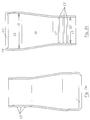
- Figure 1 shows the cable termination according to the invention in the fully applied form.
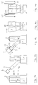
- FIG. 4a shows the cable 1 after the removal of the cable sheath 2 in the end region 9, as well as the wires 3, which mostly protrude from their wire insulation 4 due to the cutting to length.
- the individual wires 3 are bent apart in the shape of a truncated cone for further handling, and the work steps shown in FIGS. 4b to 4e are carried out on each wire: First, the burr protection cap 5 is pushed axially onto the free end of the non-stripped wire 3.
- burr protection cap 5 This can be facilitated by wetting the inside of the burr protection cap 5 or partially filling it with a lubricant 11, since the burr protection cap 5 is made of a hard, relatively non-deformable material such as a harder plastic etc., which is also due to the sharp burrs of the wires 3 must not be pierced or cut the static friction that occurs is usually so low that the lubricant is dispensed with.
- the wire insulation 4 is wrapped with a sealing tape 6, for example made of butyl, whereby the wire insulation should of course be clean and dry on the outside in order to ensure the best possible adhesion and Ensure connection with the sealing tape.
- a sealing tape 6 for example made of butyl
- the end cap of the wire end cap is placed with its bottom 19 against the end face 8 of the core or the burr protection cap, and the end cap 7 is rolled up, as shown in FIG. 4c. Due to the complete inversion of the cap, the walls of the wire end cap point from the bottom in the direction pointing away from the wire 3 at the beginning of the reeling process, so that even at the beginning of the application movement, no insertion of the wire 3 into the wire end cap 7 is necessary.
- the sealing tape 6 For the previous positioning of the sealing tape 6, it is important that it is applied in such an axial area that the annular ribs 13 which are towards the free end of the wire end cap and which point inwards when applied, press into the butyl sealing tape 6, and the wire end cap 7 preferably completely covers the sealing tape.
- the wire end cap 7 is in its normal state, as in FIG. 3a, on the left Half, shown, equipped with an essentially constant internal diameter 12 over the axial length, which is reduced only in the area of the annular circumferential ribs 13 which protrude inwards.
- An inner circumference widened in the vicinity of the bottom 19, which only becomes one Ribs 13 conically tapered - as shown in Figure 3a, right half - on the other hand makes it easier to roll up at the beginning.
- the wire end cap 7 is thus substantially expanded in diameter over its entire axial length, since the outer diameter of the burr protection cap and also the outer diameter of the applied sealing tape 6 are larger than that Inner diameter of the wire end cap 7.
- wire end cap 7 like the cable end cap 10, is made of a very elastic and deformable material, despite the preferably round inner and outer cross section of these caps, cables or wires with a non-circular cross section can also be used - such as the approximately triangular cross sections of the individual wires in a four-pole cable - be tightly closed.
- a sealing strip 6 ' is in turn wound in a ring, into which the ring-shaped and sealing ribs 13 'of the cable end cap 10 should press in.
- the circumferential ribs 13 ' which press into the sealing band 6' from the outside inward represent labyrinth seals which additionally improve the overall sealing against moisture penetrating from the outside.
- the cable end cap 10 then extends in the fully rolled-up state - as can be seen in FIG. 1 - with its free end over the area of the sealing tape 6 ', so that this is not visible from the outside, and is therefore neither accidentally destroyed nor caught or the like can be pulled out.
- FIGS. 2a and 2b in the normal state, as in FIG. 2a, there is also a ring-shaped circumferential groove at the transition area between the walls of the cable end cap 10 and the bottom 19 'in the case of the cable end cap 10 - analogous to the wire end cap 7 14 incorporated with axial alignment in the outermost edge region of the bottom 19, so that in this region the remaining wall thickness is not greater than the normal wall thickness of the end cap.
- FIGS. 2a and 2b show that the cable end cap 10 is divided into three areas in its axial course: In the end region 15 near the ground, which directly adjoins the base 19 ′, the cable end cap 10 has a constant inner diameter 12, which corresponds approximately to the outer diameter of the previously stripped end of the cable 1 equipped with burr protection caps and wire end caps. As a result, only a small amount of force is required when rolling up this first area.
- an open starting area 17 can also be seen with a constant inside diameter 12 ', which likewise does not change in this open starting area 17 except for the inwardly projecting, three annular ribs 13'.
- a cone region 16 is arranged, in which the inner diameter 12 '- in the normal state of the cable end cap 10 as shown in Figure 2a - from the side of the bottom 19' to the open end and thus to open area 17 reduced.
- this area is rolled up, a constantly increasing force will thus have to be overcome, while a constant high force has to be overcome when the open initial area 17 is rolled up. This is necessary in order to achieve the maximum radially inward pressing force in the area of the sealing tape 6 '.
- the wall thicknesses of the cable end cap 10 or the wire end cap 7 are also essentially constant and amount to 5% to 15% of the outside diameter in the normal state, preferably 1.5 mm to 4 mm.
Landscapes
- Cable Accessories (AREA)
Applications Claiming Priority (2)
| Application Number | Priority Date | Filing Date | Title |
|---|---|---|---|
| DE19944414355 DE4414355C2 (de) | 1994-04-25 | 1994-04-25 | Aufstülpbare Kabelendmuffe |
| DE4414355 | 1994-04-25 |
Publications (1)
| Publication Number | Publication Date |
|---|---|
| EP0680128A1 true EP0680128A1 (fr) | 1995-11-02 |
Family
ID=6516355
Family Applications (1)
| Application Number | Title | Priority Date | Filing Date |
|---|---|---|---|
| EP95106142A Withdrawn EP0680128A1 (fr) | 1994-04-25 | 1995-04-24 | Manchon susceptible d'être enroulé sur une extrémité de câble |
Country Status (2)
| Country | Link |
|---|---|
| EP (1) | EP0680128A1 (fr) |
| DE (1) | DE4414355C2 (fr) |
Cited By (4)
| Publication number | Priority date | Publication date | Assignee | Title |
|---|---|---|---|---|
| EP0783196A3 (fr) * | 1996-01-05 | 1999-05-12 | AT&T Corp. | Capuchon d'inhibition de corrosion pour terminaux électriques |
| EP0880212A3 (fr) * | 1997-05-19 | 1999-12-01 | N.V. Raychem S.A. | Fermeture d'épissure de cable |
| EP2251951A1 (fr) * | 2009-05-14 | 2010-11-17 | Alcatel Lucent | Dispositif, assemblage et son procédé de scellement |
| WO2021156622A1 (fr) * | 2020-02-06 | 2021-08-12 | Hubbell Limited | Goupilles de câble |
Families Citing this family (3)
| Publication number | Priority date | Publication date | Assignee | Title |
|---|---|---|---|---|
| FR2774523B1 (fr) * | 1998-01-30 | 2000-04-07 | Electricite Radio Aviat Mecani | Manchon d'etancheite retractable a froid pour cable electrique |
| DE102012005545A1 (de) * | 2012-03-21 | 2013-09-26 | Phoenix Contact Gmbh & Co. Kg | Kabelabschlusseinrichtung |
| DE202022101102U1 (de) | 2022-02-28 | 2023-06-05 | WAGO Verwaltungsgesellschaft mit beschränkter Haftung | Leiterendkappe |
Citations (5)
| Publication number | Priority date | Publication date | Assignee | Title |
|---|---|---|---|---|
| US2145705A (en) * | 1936-10-16 | 1939-01-31 | Anaconda Wire & Cable Co | Cushion cap for insulated cables |
| DE7045286U (de) * | 1970-12-03 | 1971-08-12 | Vereinigte Draht Und Kabelwerke Ag | Kabelendenabschluß |
| US3992570A (en) * | 1973-12-12 | 1976-11-16 | Amp Incorporated | Cable end sealing devices |
| DE9011333U1 (de) * | 1990-08-02 | 1990-10-04 | LIC Langmatz GmbH, 8100 Garmisch-Partenkirchen | Abnehmbarer Endverschluß für elektrische Leitungskabel |
| EP0398210A2 (fr) * | 1989-05-18 | 1990-11-22 | Alcatel IKO Kabel Aktiebolag | Recouvrement pour l'extrémité d'un cable, tuyau on similaire |
-
1994
- 1994-04-25 DE DE19944414355 patent/DE4414355C2/de not_active Expired - Fee Related
-
1995
- 1995-04-24 EP EP95106142A patent/EP0680128A1/fr not_active Withdrawn
Patent Citations (5)
| Publication number | Priority date | Publication date | Assignee | Title |
|---|---|---|---|---|
| US2145705A (en) * | 1936-10-16 | 1939-01-31 | Anaconda Wire & Cable Co | Cushion cap for insulated cables |
| DE7045286U (de) * | 1970-12-03 | 1971-08-12 | Vereinigte Draht Und Kabelwerke Ag | Kabelendenabschluß |
| US3992570A (en) * | 1973-12-12 | 1976-11-16 | Amp Incorporated | Cable end sealing devices |
| EP0398210A2 (fr) * | 1989-05-18 | 1990-11-22 | Alcatel IKO Kabel Aktiebolag | Recouvrement pour l'extrémité d'un cable, tuyau on similaire |
| DE9011333U1 (de) * | 1990-08-02 | 1990-10-04 | LIC Langmatz GmbH, 8100 Garmisch-Partenkirchen | Abnehmbarer Endverschluß für elektrische Leitungskabel |
Cited By (7)
| Publication number | Priority date | Publication date | Assignee | Title |
|---|---|---|---|---|
| EP0783196A3 (fr) * | 1996-01-05 | 1999-05-12 | AT&T Corp. | Capuchon d'inhibition de corrosion pour terminaux électriques |
| US6300574B1 (en) | 1996-01-05 | 2001-10-09 | Lucent Technologies Inc. | Corrosion inhibiting cap for electrical terminals |
| EP0880212A3 (fr) * | 1997-05-19 | 1999-12-01 | N.V. Raychem S.A. | Fermeture d'épissure de cable |
| EP2251951A1 (fr) * | 2009-05-14 | 2010-11-17 | Alcatel Lucent | Dispositif, assemblage et son procédé de scellement |
| WO2021156622A1 (fr) * | 2020-02-06 | 2021-08-12 | Hubbell Limited | Goupilles de câble |
| GB2591775B (en) * | 2020-02-06 | 2024-10-30 | Hubbell Ltd | Cable glands |
| US12316082B2 (en) | 2020-02-06 | 2025-05-27 | Hubbell Limited | Cable glands with multiple seal positions |
Also Published As
| Publication number | Publication date |
|---|---|
| DE4414355C2 (de) | 1998-04-09 |
| DE4414355A1 (de) | 1995-10-26 |
Similar Documents
| Publication | Publication Date | Title |
|---|---|---|
| DE69707915T2 (de) | Kabelumhüllungsanordnung | |
| DE3505214C2 (de) | Verfahren zum Aufbringen eines elastischen Schlauchstückes auf ein Ende eines länglichen Körpers | |
| DE69014344T2 (de) | Elektrische Verbindereinrichtung eines Kabels, namentlich Zündkabels, an einer Klemme. | |
| DE3943296A1 (de) | Muffe zum einhuellen einer verbindung oder eines endes eines elektrokabels | |
| DE2729100B2 (de) | ErdungsanschluB für ein Kabel, insbesondere für ein Hochspannungskabel | |
| DE19510598A1 (de) | Aufschiebehilfe für das Aufschieben und Positionieren von hülsenförmigen, elastischen Bauteilen auf zylindrische oder konische Grundkörper | |
| DE69022234T2 (de) | Durchführungsverbinder für koaxiale kabel. | |
| DE69711454T2 (de) | Vorrichtung zum kompakten umhüllen | |
| DE7800585U1 (de) | Staubsaugerschlauch | |
| DE3220067A1 (de) | Verbesserungen bei elektrischen kabelverbindungen und/oder kabelabschluessen | |
| DE4414355C2 (de) | Aufstülpbare Kabelendmuffe | |
| DE69305181T2 (de) | Kabelspleissverschluss | |
| DE19900201C2 (de) | Kabelanschluß- oder -verbindungseinrichtung | |
| DE69616381T2 (de) | Klemmvorrichtung | |
| DE3422793C2 (fr) | ||
| DE9002070U1 (de) | Adapter für einen elektrischen Kabelabschluß | |
| DE102020134636B4 (de) | Kappe zur lösbaren Befestigung an Leitungen und anderen länglichen Elementen | |
| DE69402062T2 (de) | Kabeldichtung und sicherungsvorrichtung | |
| EP0546288B1 (fr) | Joint d'étanchéité pour câbles électriques unifilaires | |
| DE2609078C3 (de) | Übergangsmuffe | |
| DE69010981T2 (de) | Endabdeckung für ein Kabel, Rohr oder ähnliches. | |
| DE8912585U1 (de) | Manschettenartiges Abdichtelement | |
| DE69504106T2 (de) | Radial aufgeweitete, modulare sperrhülle | |
| DE8709907U1 (de) | Vorrichtung zum Einziehen von Kabeln in Kabelschutzrohre | |
| DE3532118C2 (fr) |
Legal Events
| Date | Code | Title | Description |
|---|---|---|---|
| PUAI | Public reference made under article 153(3) epc to a published international application that has entered the european phase |
Free format text: ORIGINAL CODE: 0009012 |
|
| AK | Designated contracting states |
Kind code of ref document: A1 Designated state(s): AT BE CH DE DK FR GB IT LI LU NL SE |
|
| RAX | Requested extension states of the european patent have changed |
Free format text: SI |
|
| 17P | Request for examination filed |
Effective date: 19951012 |
|
| 17Q | First examination report despatched |
Effective date: 19970128 |
|
| GRAG | Despatch of communication of intention to grant |
Free format text: ORIGINAL CODE: EPIDOS AGRA |
|
| GRAG | Despatch of communication of intention to grant |
Free format text: ORIGINAL CODE: EPIDOS AGRA |
|
| GRAH | Despatch of communication of intention to grant a patent |
Free format text: ORIGINAL CODE: EPIDOS IGRA |
|
| STAA | Information on the status of an ep patent application or granted ep patent |
Free format text: STATUS: THE APPLICATION IS DEEMED TO BE WITHDRAWN |
|
| 18D | Application deemed to be withdrawn |
Effective date: 19981013 |