EP0680176A2 - Verfahren zum Sammeln von Knoteninformation in einem Ringsystem - Google Patents
Verfahren zum Sammeln von Knoteninformation in einem Ringsystem Download PDFInfo
- Publication number
- EP0680176A2 EP0680176A2 EP95104659A EP95104659A EP0680176A2 EP 0680176 A2 EP0680176 A2 EP 0680176A2 EP 95104659 A EP95104659 A EP 95104659A EP 95104659 A EP95104659 A EP 95104659A EP 0680176 A2 EP0680176 A2 EP 0680176A2
- Authority
- EP
- European Patent Office
- Prior art keywords
- node
- nodes
- node information
- information
- response signal
- Prior art date
- Legal status (The legal status is an assumption and is not a legal conclusion. Google has not performed a legal analysis and makes no representation as to the accuracy of the status listed.)
- Withdrawn
Links
Images


Classifications
-
- H—ELECTRICITY
- H04—ELECTRIC COMMUNICATION TECHNIQUE
- H04L—TRANSMISSION OF DIGITAL INFORMATION, e.g. TELEGRAPHIC COMMUNICATION
- H04L12/00—Data switching networks
- H04L12/28—Data switching networks characterised by path configuration, e.g. LAN [Local Area Networks] or WAN [Wide Area Networks]
- H04L12/42—Loop networks
- H04L12/437—Ring fault isolation or reconfiguration
-
- H—ELECTRICITY
- H04—ELECTRIC COMMUNICATION TECHNIQUE
- H04L—TRANSMISSION OF DIGITAL INFORMATION, e.g. TELEGRAPHIC COMMUNICATION
- H04L43/00—Arrangements for monitoring or testing data switching networks
-
- H—ELECTRICITY
- H04—ELECTRIC COMMUNICATION TECHNIQUE
- H04L—TRANSMISSION OF DIGITAL INFORMATION, e.g. TELEGRAPHIC COMMUNICATION
- H04L43/00—Arrangements for monitoring or testing data switching networks
- H04L43/08—Monitoring or testing based on specific metrics, e.g. QoS, energy consumption or environmental parameters
- H04L43/0805—Monitoring or testing based on specific metrics, e.g. QoS, energy consumption or environmental parameters by checking availability
- H04L43/0817—Monitoring or testing based on specific metrics, e.g. QoS, energy consumption or environmental parameters by checking availability by checking functioning
Definitions
- the present invention relates to a network in which a plurality of nodes are interconnected in a ring-like manner and, more specifically, to a method and a system of collecting information indicating operation states of the respective nodes.
- the network faults are classified into node faults and transmission line faults. While the transmission line faults are now very rare by virtue of the introduction of optical transmission lines, the node faults occupy a large proportion of the network faults. Particularly in a large-scale ring network having a large number of nodes, since the probability of occurrences of node faults is accordingly high, it is important to quickly identify a node of fault occurrence and effect a proper measure.
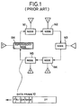
- FIG. 1 An example of a fault detecting method in a ring network is disclosed in Japanese Patent Application Laid-open No. Sho 63-246946, and will be explained below.
- a communication between nodes is performed by circulating a data frame 10 in a direction indicated by arrows.
- the data frame 10 includes a destination address DA, a source address SA, a use indication B/I indicating whether the data frame 10 is in use or not, and a supervisory indication bit M.
- a certain node When a certain node attempts to use a data frame 10 for an internode communication, it sends the data frame 10 to a ring transmission line after setting its use indication B/I and resetting its supervisory indication M. Receiving the data frame 10, which is in use, the supervisory node SN sends it to the ring transmission line after setting the supervisory indication M. When the data frame 10 is received by the destination node and then sent to the ring transmission line, at least the supervisory indication M is reset at that time. If the data frame 10 is not received by any node, it is again received by the supervisory node SN with both of its use indication B/I and supervisory indication M in a set state. Therefore, the supervisory node SN can identify a node of fault occurrence by analyzing the destination address and the source address of the data frame 10 whose use indication B/I and supervisory indication M are both in a set state.
- An object of the present invention is to provide an information collecting method which can quickly collect information of all the nodes that constitutes a ring network system.
- Another object of the invention is to provide an information collecting method which can quickly identify a node of fault occurrence in a ring network system.
- a further object of the invention is to provide a highly reliable ring network system which can quickly identify a node of fault occurrence.
- each node is provided with a node information table which can store information of all the nodes of the ring network at respective prescribed memory locations.
- the node information table is logically divided into node ares each corresponding to a single node within the ring network.
- Each node collects node information stored in the node information tables of the two adjacent nodes by regularly accessing the node information tables of those nodes, and updates the contents of its own node information table. As a result of the above information collecting operation that is performed by each node, all the node information can be stored in the node information table of each node.
- a node information collecting method self-node information in each the node itself is stored in the node information table at predetermined time intervals, and access to two nodes clockwise and counterclockwise adjacent to each the node is made to collect node information retained in the node information tables of the two adjacent nodes at the predetermined time intervals so that each the node stores node information of all the nodes.
- the access to the adjacent nodes is preferably performed using a demand signal and a response signal.
- the demand signal is transmitted from each the node to the two adjacent nodes for requesting the node information stored in the two adjacent nodes.
- the nodes NDa-NDe are provided with respective alarm information tables AITa-AITe, each of which stores alarm information of all the nodes NDa-NDe of the ring network and is always updated at regular time intervals.
- the alarm information table AIT of each node is updated such that each node transmits a demand signal DMD to the adjacent nodes and receives a response signal RSP from those nodes.
- the demand signal DMD is a signal that requests the adjacent nodes to transmit alarm information stored in their alarm information tables AIT.
- the response signal RSP is a data signal carrying alarm information that is transmitted in response to the demand signal DMD.
- each node is provided with a serial communication controllers 101 and 102 that are connected to the respective transmission lines.
- the communication operation of the node is controlled by a controller 103.
- the alarm information table AIT is included in a memory 104, and stores alarm information ALM that is output from a supervisory system 105 at a prescribed address at predetermined time intervals. When a certain fault occurs in the node, the supervisory system 105, which is known well, outputs alarm information ALM indicating the fault occurrence.
- a terminal T is connected to the node via an I/O interface 106.
- demand signals DMD are sent from the serial communication controllers 101 and 102 to the respective adjacent nodes at predetermined time intervals.
- the controller 103 Upon reception of response signals RSP from the adjacent nodes in response to the demand signals DMD, the controller 103 write alarm information of the received response signals RSP to the alarm information table AIT at respective prescribed addresses.
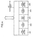
- FIG. 4 shows an area configuration of the alarm information table AIT.
- the central area 203 corresponds to the node to which the alarm information table AIT concerned belongs.
- the areas 202 and 204 adjacent to the central area 203 correspond to the nodes adjacent to the node concerned. More specifically, the area 202 corresponds to the node that is adjacent to the node concerned in the clockwise direction CW, and the area 204 corresponds to the node that is adjacent to the node concerned in the counterclockwise direction CCW.
- the area 201 corresponds to the node that is adjacent but one to the node concerned in the clockwise direction CW, and the area 205 corresponds to the node that is adjacent but one to the node concerned in the counterclockwise direction CCW.
- the alarm information ALMa-ALMe of the nodes NDa-NDe are stored in the areas 201-205 of the alarm information table AITc, respectively.
- the alarm information ALMd, ALMe, ALMa, ALMb and ALMc of the nodes NDd, NDe, NDa, NDb and NDc are stored in the areas 201-205 of the alarm information table AITa, respectively.
- FIG. 5 is a flowchart showing a communication operation of an arbitrary node.
- a judgment is made on the kind of a signal received from the transmission line (S301). Operations described below are performed for the respective cases of a demand signal DMD, a response signal RSP, a data signal, and absence of a receiving signal.
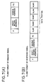
- FIGS. 7(A) and 7(B) frame formats of the demand signal DMD and the response signal RSP are shown in FIGS. 7(A) and 7(B), respectively Discrimination among the demand signal DMD, response signal RSP and data signal is made based on a frame control bit "FC" that follows a source address "SA" in each frame format.
- the data portion of the response signal RSP is comprised of sections ALM1-ALM5 corresponding to the respective areas 201-205 of the alarm information table AIT of each node.
- step S302 When no receiving signal is present, it is judged whether a predetermined time period (several milliseconds) has elapsed which determines the transmission interval of the demand signal DMD (S302). If the time interval equal to the transmission interval has elapsed (Yes in step S302), the controller 103 of the node reads alarm information ALM at that time from the supervisory system 105 (S303), and stores it into the central area 203 of the alarm information table AIT (S304). Then, the controller 103 sends demand signals DMD to the node that is adjacent to the node concerned in the CW direction and the node that is adjacent to the node concerned in the CCW direction while controlling the serial communication controllers 101 and 102 (S305). Then, a timer is reset to restart its counting operation for the transmission interval (S306). The alarm information of the node is not updated and no demand signals DMD are transmitted (No in S302) until the time equal to the transmission interval has elapsed.
- a predetermined time period severe
- a response signal RSP When a response signal RSP is received in response to the demand signal DMD, it is judged, based on the destination address of the response signal RSP, which sent the response signal RSP, the CW-adjacent node or the CCW-adjacent node (S401). If the response signal RSP was sent from the adjacent node in the CW direction, data (alarm information) of the sections ALM2 and ALM3 in the data portion of the response signal RSP are read (S402) and substituted for the data of the areas 201 and 202 of the alarm information table AIT (S403).
- a demand signal DMD When a demand signal DMD is received, it is judged, based on the destination address, from which of the adjacent nodes in the CW and CCW directions the demand signal DMD was sent (S501). If the demand signal DMD was received from the adjacent node in the CW direction, a response signal RSP is generated in which data of all the areas 201-205 of the alarm information table AIT are transferred to the data portion ALM1-ALM5 and transmitted to the adjacent node in the CW direction (S502).
- a response signal RSP is generated in which data of all the areas 201-205 of the alarm information table AIT are transferred to the data portion ALM1-ALM5 and transmitted to the, adjacent node in the CCW direction (S503).
- the above described series of operations including the transmission of a demand signal DMD, the reception of a response signal RSP, and the updating of the table AIT are repeated in each node at the predetermined time intervals.
- the alarm information of all the nodes is stored in the alarm information table AIT of each node, and is always updated at the predetermined time intervals.
- all of the areas 201-205 of the alarm information table AIT of each node can be filled by two times of information collecting operations, i.e., by repeating two times the series of operations including the transmission of a demand signal DMD (S305), the reception of a response signal RSP, and the updating of the table AIT (S401-S405).
- the information collecting operation is repeated by the number of times that is equal to a quotient of N/2, because each node collects information from the two adjacent nodes. For example, in a system having 6 or 7 nodes, the information collecting operation is repeated three times. In a system having 8 or 9 nodes, the information collecting operation is repeated four times.
- alarm information tables AITa-AITe that is, the areas 201, 202, 204 and 205 corresponding to the nodes other than the self node are in a cleared state, i.e., a default state indicated by mark "-" in FIG. 6.
- Row (1) in FIG. 6 shows states of the respective nodes immediately after the system start-up. Specifically, alarm information ALMa of the node NDa is stored in the central area 203 of the table AITa.
- alarm information ALMb of the node NDb is stored in the area 203 of the table AITb
- alarm information ALMc of the node NDc is stored in the area 203 of the table AITc
- alarm information ALMd of the node NDd is stored in the area 203 of the table AITd
- alarm information ALMe of the node NDe is stored in the area 203 of the table AITe.
- a first alarm information collecting operation is performed by sending demand signals DMDc-b and DMDc-d from the node NDc to the adjacent nodes NDb and NDd in the CW and CCW directions, respectively.
- the node NDb sends (or returns) to the node NDc a response signal RSPb-c conveying data of all the areas of the table AITb, i.e., only the alarm information ALMb of the self node at this time.
- the node NDd when receiving the first demand signal DMDc-d from the node NDc, the node NDd sends (or returns) to the node NDc a response signal RSPd-c conveying data of all the areas of the table AITd, i.e., only the alarm information ALMd of the self node at this time.
- the node NDc stores the alarm information ALMb of the node NDb into the area 202 of the table AITc based on the response signal RSPb-c and also stores the alarm information ALMd of the node NDd into the area 204 based on the response signal RSPd-c. This state is shown in the table AITc in row (2) of FIG. 6.
- the node NDc collects alarm information of the adjacent nodes NDb and NDd by accessing those nodes by using the demand signals DMDc-b and DMDc-d.
- the node NDc is accessed by the adjacent nodes NDb and NDd by demand signals DMDb-c and DMDd-c, and sends (or returns) to the respective nodes NDb and NDd response signals RSPc-b and RSPc-d comprising the alarm signal ALMc retained by the self node (at this time, the alarm signals ALMb and ALMd of the respective nodes NDb and NDd are not stored in the table AITc yet).
- the node NDb accesses the node NDa by using a demand signal DMDb-a.
- the node NDd accesses the node NDe by using a demand signal DMDd-e. Therefore, as shown in row (2) of FIG. 6, after the first information collecting operation, alarm information is stored in the areas 202, 203 and 204 of the alarm information table AIT of each node.
- the node NDc performs a second information collecting operation by sending the same demand signals DMDc-b and DMDc-d as in the first operation to the respective nodes NDb and NDd.
- Response signals RSPb-c and RSPd-c are returned from the respective nodes NDb and NDd in response to the above accessing.
- the response signals RSPb-c and RSPd-c include the alarm information that was sent at the time of the first information collecting operation shown in row (2) of FIG. 6. Therefore, as shown in row (3) of FIG.
- the alarm information ALMa-ALMe of all the nodes are stored in all of the areas 201-205 of the alarm information table AITc of the node NDc. The same thing applies to the alarm tables AIT of the other nodes.
- each node of a ring network can collect alarm information of all the nodes by always accessing the adjacent nodes at predetermined time intervals.
- a network control station can recognize alarm states of all the nodes by accessing any node, and can identify a node of fault occurrence immediately.
- each node can collect alarm information of the two adjacent nodes at one time, the alarm information collecting operation can be performed more than two times faster than in the conventional case where alarm information is collected by circulating a data frame from a supervisory node through a ring network system in a single direction.
- the invention does not have the concept of a supervisory node. Rather, every node on the ring network simultaneously accesses the two nodes that are adjacent to it in the CW and CCW directions. Therefore, alarm information of the two adjacent nodes can be collected at one time, and the information collecting operation can be performed more than two times faster than in the case where alarm information is collected by accessing the nodes in a single direction of a ring network. Further, even where a fault occurs in a transmission line between certain nodes, alarm information of all the nodes can be collected by continuing the accessing either clockwise or counterclockwise with the same results as in the case of the accessing in both directions. Thus, influences of a transmission line fault are negligible.
Landscapes
- Engineering & Computer Science (AREA)
- Computer Networks & Wireless Communication (AREA)
- Signal Processing (AREA)
- Small-Scale Networks (AREA)
Applications Claiming Priority (2)
| Application Number | Priority Date | Filing Date | Title |
|---|---|---|---|
| JP6059524A JPH07273785A (ja) | 1994-03-29 | 1994-03-29 | リングシステムにおけるノード間情報収集方式 |
| JP59524/94 | 1994-03-29 |
Publications (2)
| Publication Number | Publication Date |
|---|---|
| EP0680176A2 true EP0680176A2 (de) | 1995-11-02 |
| EP0680176A3 EP0680176A3 (de) | 1997-07-16 |
Family
ID=13115750
Family Applications (1)
| Application Number | Title | Priority Date | Filing Date |
|---|---|---|---|
| EP95104659A Withdrawn EP0680176A3 (de) | 1994-03-29 | 1995-03-29 | Verfahren zum Sammeln von Knoteninformation in einem Ringsystem. |
Country Status (3)
| Country | Link |
|---|---|
| US (1) | US5590117A (de) |
| EP (1) | EP0680176A3 (de) |
| JP (1) | JPH07273785A (de) |
Cited By (2)
| Publication number | Priority date | Publication date | Assignee | Title |
|---|---|---|---|---|
| EP0886164A3 (de) * | 1997-06-19 | 2005-06-22 | Yazaki Corporation | Verfahren zur Störungsbeseitigung und Kommunikationssystem |
| EP1439671A3 (de) * | 2002-11-07 | 2008-12-31 | Honda Motor Company Ltd. | Netzwerksempfänger, Datensender/-empfänger, und Verfahren zur Fehlerlokalisierung/Kompensation |
Families Citing this family (9)
| Publication number | Priority date | Publication date | Assignee | Title |
|---|---|---|---|---|
| JP3307508B2 (ja) * | 1994-09-01 | 2002-07-24 | 富士通株式会社 | 通信ネットワーク構成検出方法 |
| DE19503206C1 (de) * | 1995-02-02 | 1996-08-14 | Becker Gmbh | Verfahren zur Bestimmung der Position eines Netzteilnehmers in einem Netzwerk bei einer auftretenden Leitungsstörung |
| JP2617701B2 (ja) * | 1995-06-28 | 1997-06-04 | 宮城日本電気株式会社 | Vtパス切替時のミスコネクション回避方法 |
| US6047309A (en) * | 1995-10-02 | 2000-04-04 | International Business Machines Corporation | Recording observed and reported response characteristics at server and/or client nodes in a replicated data environment, and selecting a server to provide data based on the observed and/or reported response characteristics |
| US5740346A (en) * | 1996-02-22 | 1998-04-14 | Fujitsu, Ltd. | System and method for dynamic network topology exploration |
| US7058024B1 (en) * | 1999-02-03 | 2006-06-06 | Lucent Technologies, Inc. | Automatic telecommunications link identification system |
| US6987735B2 (en) * | 2001-05-24 | 2006-01-17 | International Business Machines Corporation | System and method for enhancing the availability of routing systems through equal cost multipath |
| US7218852B1 (en) * | 2001-12-21 | 2007-05-15 | Ciena Corporation | System and method for optical light path discovery |
| US20140201326A1 (en) * | 2013-01-16 | 2014-07-17 | Marvell World Trade Ltd. | Interconnected ring network in a multi-processor system |
Family Cites Families (7)
| Publication number | Priority date | Publication date | Assignee | Title |
|---|---|---|---|---|
| JPS63246946A (ja) * | 1987-04-02 | 1988-10-13 | Fujitsu Ltd | ル−プ構造ネツトワ−クにおける通信装置の障害検出方式 |
| GB8817288D0 (en) * | 1988-07-20 | 1988-08-24 | Racal Milgo Ltd | Methods of & networks for information communication |
| US5285448A (en) * | 1990-03-01 | 1994-02-08 | Hitachi, Ltd. | Transmission system of system of system control information in a ring LAN system |
| US5442620A (en) * | 1992-03-26 | 1995-08-15 | At&T Corp. | Apparatus and method for preventing communications circuit misconnections in a bidirectional line-switched ring transmission system |
| JPH0677979A (ja) * | 1992-08-27 | 1994-03-18 | Fujitsu Ltd | 状態監視方法 |
| JP2576762B2 (ja) * | 1993-06-30 | 1997-01-29 | 日本電気株式会社 | リング網のノード間情報収集方式 |
| US5412652A (en) * | 1993-09-24 | 1995-05-02 | Nec America, Inc. | Sonet ring subnetwork management method |
-
1994
- 1994-03-29 JP JP6059524A patent/JPH07273785A/ja active Pending
-
1995
- 1995-03-29 EP EP95104659A patent/EP0680176A3/de not_active Withdrawn
- 1995-03-29 US US08/413,102 patent/US5590117A/en not_active Expired - Lifetime
Cited By (2)
| Publication number | Priority date | Publication date | Assignee | Title |
|---|---|---|---|---|
| EP0886164A3 (de) * | 1997-06-19 | 2005-06-22 | Yazaki Corporation | Verfahren zur Störungsbeseitigung und Kommunikationssystem |
| EP1439671A3 (de) * | 2002-11-07 | 2008-12-31 | Honda Motor Company Ltd. | Netzwerksempfänger, Datensender/-empfänger, und Verfahren zur Fehlerlokalisierung/Kompensation |
Also Published As
| Publication number | Publication date |
|---|---|
| JPH07273785A (ja) | 1995-10-20 |
| EP0680176A3 (de) | 1997-07-16 |
| US5590117A (en) | 1996-12-31 |
Similar Documents
| Publication | Publication Date | Title |
|---|---|---|
| EP0238364B1 (de) | Bedienplatzgerät, welches eine zentrale Ueberwachung von in Gruppen stehenden Datenverarbeitungssystem erlaubt, und Verfahren, welches ein derartiges Bedienplatzgerät benützt. | |
| US5590117A (en) | Node information collecting method in a ring system | |
| GB2194713A (en) | Method of restoring transmission | |
| EP0898398B1 (de) | Verfahren und Vorrichtung zur Wiedersynchronisierung eines Netzverwalters mit seinen Netzwerkagenten | |
| EP1485807B1 (de) | Verteilter fehlerbeständiger gemeinsam benutzter speicher | |
| US4759015A (en) | Ring network system for transmission of multicast information | |
| US6243830B1 (en) | State information managing method and communication system | |
| US5327425A (en) | Network synchronization control system and control method | |
| US4779087A (en) | Loop transmission system with frame synchronization control | |
| KR920007099B1 (ko) | 지역네트워크간 통신 시스템(system for internetwork communication between local area networks) 및 통신방법 | |
| JPH07183905A (ja) | 遠隔監視システム | |
| JP3896660B2 (ja) | ネットワークの監視システム | |
| US5331647A (en) | Communication apparatus having function to record communication history | |
| JPH07262042A (ja) | プロセッサ障害検出方法 | |
| JP3137197B2 (ja) | マルチプロセッサシステム | |
| JP3076676B2 (ja) | リモートブリッジ | |
| JP2606585B2 (ja) | リングネットワークシステム及びリングネットワークシステムにおけるノード情報収集方法 | |
| CN120812071B (zh) | 一种分布式单片机状态同步的管理方法 | |
| JP3197946B2 (ja) | ループ型ネットワークの運用管理方法 | |
| JPH0823342A (ja) | リング伝送路におけるプロテクション情報管理システム | |
| JP3113165B2 (ja) | デュアルポートram通信方法 | |
| JP3439365B2 (ja) | 転送制御システムのノード障害検出方法およびファイル転送時のノード障害検出方法 | |
| AU577684B2 (en) | Loop transmission system with frame synchronization control | |
| JPH02282835A (ja) | 情報処理装置の保守診断装置 | |
| JPH0687559B2 (ja) | バス型lan |
Legal Events
| Date | Code | Title | Description |
|---|---|---|---|
| PUAI | Public reference made under article 153(3) epc to a published international application that has entered the european phase |
Free format text: ORIGINAL CODE: 0009012 |
|
| AK | Designated contracting states |
Kind code of ref document: A2 Designated state(s): DE FR GB |
|
| PUAL | Search report despatched |
Free format text: ORIGINAL CODE: 0009013 |
|
| AK | Designated contracting states |
Kind code of ref document: A3 Designated state(s): DE FR GB |
|
| 17P | Request for examination filed |
Effective date: 19970616 |
|
| 17Q | First examination report despatched |
Effective date: 20020219 |
|
| STAA | Information on the status of an ep patent application or granted ep patent |
Free format text: STATUS: THE APPLICATION IS DEEMED TO BE WITHDRAWN |
|
| 18D | Application deemed to be withdrawn |
Effective date: 20020820 |