EP0680194B1 - Dispositif de traitement d'images et dispositif de sortie d'images pour la conversion d'une image binaire en une image à valeurs multiples - Google Patents
Dispositif de traitement d'images et dispositif de sortie d'images pour la conversion d'une image binaire en une image à valeurs multiples Download PDFInfo
- Publication number
- EP0680194B1 EP0680194B1 EP95106333A EP95106333A EP0680194B1 EP 0680194 B1 EP0680194 B1 EP 0680194B1 EP 95106333 A EP95106333 A EP 95106333A EP 95106333 A EP95106333 A EP 95106333A EP 0680194 B1 EP0680194 B1 EP 0680194B1
- Authority
- EP
- European Patent Office
- Prior art keywords
- image
- areas
- lines
- processing device
- binary
- Prior art date
- Legal status (The legal status is an assumption and is not a legal conclusion. Google has not performed a legal analysis and makes no representation as to the accuracy of the status listed.)
- Expired - Lifetime
Links
- 238000012545 processing Methods 0.000 title claims description 171
- 238000000034 method Methods 0.000 claims description 63
- 238000012937 correction Methods 0.000 claims description 21
- 230000015654 memory Effects 0.000 claims description 18
- 238000000926 separation method Methods 0.000 claims description 17
- 238000009792 diffusion process Methods 0.000 claims description 8
- 238000001514 detection method Methods 0.000 description 55
- 238000010586 diagram Methods 0.000 description 7
- 238000012935 Averaging Methods 0.000 description 6
- 230000005540 biological transmission Effects 0.000 description 4
- 238000013500 data storage Methods 0.000 description 4
- 238000009499 grossing Methods 0.000 description 4
- 230000009931 harmful effect Effects 0.000 description 4
- 238000013528 artificial neural network Methods 0.000 description 3
- 230000000694 effects Effects 0.000 description 3
- 230000003287 optical effect Effects 0.000 description 3
- 230000015556 catabolic process Effects 0.000 description 2
- 239000003086 colorant Substances 0.000 description 2
- 238000006731 degradation reaction Methods 0.000 description 2
- 230000000593 degrading effect Effects 0.000 description 2
- 238000001914 filtration Methods 0.000 description 2
- 239000011159 matrix material Substances 0.000 description 2
- 238000004891 communication Methods 0.000 description 1
- 230000003247 decreasing effect Effects 0.000 description 1
- 230000001419 dependent effect Effects 0.000 description 1
- 238000003708 edge detection Methods 0.000 description 1
- 230000005055 memory storage Effects 0.000 description 1
- 238000012986 modification Methods 0.000 description 1
- 230000004048 modification Effects 0.000 description 1
Images


Classifications
-
- H—ELECTRICITY
- H04—ELECTRIC COMMUNICATION TECHNIQUE
- H04N—PICTORIAL COMMUNICATION, e.g. TELEVISION
- H04N1/00—Scanning, transmission or reproduction of documents or the like, e.g. facsimile transmission; Details thereof
- H04N1/40—Picture signal circuits
- H04N1/40062—Discrimination between different image types, e.g. two-tone, continuous tone
Definitions
- the present invention generally relates to image processing devices, and more particularly relates to an image processing device which converts an input binary image into a multi-valued image.
- the method (a) can demonstrate its effect to some degree.
- the method (a) brings about an image degradation in letter images and line drawings.
- the method (c) which detects edges and changes the aperture size of the smoothing filter in order to preserve an edge sharpness brings about image degradation as well.
- the method (b) which uses the neural network requires huge hardware, which is not desirable, and does not offer a proven effect for an unlearned image.
- the method (d) and (e) require only a small amount of hardware, since they switch the types of image processing based on results of the image-area-separation processing on binary images.
- the use of the dither matrixes for identifying concentrated-pseudo-halftones leads to a poor resolution.
- letters or line drawings can be degraded, or photographic image areas can be partly left unchanged to multi-values.
- the method (f) eliminates jagged edges of letter images or line drawings and can create problems in processing photographs and graphic images.
- a processing apparatus capable of discriminating between pseudo-halftone/non-halftone image data based upon the number of adjacencies of similar type of pixels within a block is known from JP-A-4330864 corresponding to US-A-5,459,587.
- the image processing apparatus for processing inputted binary image data including a first area in which data are binarized by a pseudo half-tone binarizing method and a second area in which data are binarized using a predetermined threshold value by a non-half-tone binarizing method, there is calculated a number of adjacencies representing an adjacency state of the same kind of pixels located within a block area composed of a plurality of pixels including a specified pixel to be processed. Further, there is judged whether each pixel of the inputted binary image data is included in the first area or the second area, based on the calculated number of adjacencies.
- an image processing device converting a binary image into multi-valued output image includes an image-area-separation processing unit detecting shadow areas in the binary image, wherein the shadow areas are graphic or photographic image areas having more than a predetermined number cf lines, an outline-correction processing unit correcting jagged edges in the binary image to generate a corrected image, a multi-value processing unit converting the binary image into a multi-valued image through a filtering process, and a selection unit selecting the multi-valued image for the shadow areas and the corrected image for areas other than the shadow areas so as to generate the multi-valued output image.
- the photographic or graphic images comprised of a large number cf lines are made into multi-valued images by using filters, so that the photographic or graphic images comprised of a large number cf lines can be represented in gray levels. Also, only image areas other than the photographic or graphic image areas having the large number of lines are subject to an outline-correction processing for correcting the jagged edges. Thus, the outline-correction processing can be prevented from having a harmful effect on the photographic or graphic image areas having the large number of lines.
- an image output device which can convert a binary image into a multi-valued image of an improved image quality while eliminating jagged edges of letter images and line drawings.
- an image output device includes a memory storing a binary image, an image-area-separation processing unit detecting shadow areas in the binary image, wherein the shadow areas are graphic or photographic image areas having more than a predetermined number of lines, an outline-correction processing unit correcting jagged edges in the binary image to generate a corrected image, a multi-value processing unit converting the binary image into a multi-valued image through a filtering process, a selection unit selecting the multi-valued image for the shadow areas and the corrected image for areas other than the shadow areas so as to generate an output image, and an output device printing the output image.
- the image output device of the present invention can print the output image which is the multi-valued image generated from the binary image. Also, the output image has an improved image quality, and the jagged edges which existed in the binary image are eliminated in the output image.
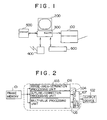
- Fig.1 shows an illustrative drawing of a system using an image processing device according to the present invention.
- the system includes a printer 100 such as a laser printer having an image processing device 106 of the present invention inside, a display 200, a computer 300, a modem 400, a external data storage 400 such as a hard drive or an optical-disk drive, and a scanner 600.
- the modem 400 is provided for modulating and demodulating image data when transmitting or receiving a facsimile.
- An advantage of having the image processing device 106 in the system can be seen, for example, in a case in which the printer 100 prints a document created by an application program of the computer 300.
- a page memory provided in the printer 100 such as a laser printer is comprised of 1-bit pixels as a cost-reduction factor, providing only a binary-image capacity for an image to be printed.
- letters and line drawings can be represented by 1-bit pixels
- photographs and graphic images are normally comprised of pixels of multi-values.
- photographs and graphic images should be converted into pseudo-halftone images having binary pixels to be stored in the page memory. This means that an image displayed on the display 200 may be different from that printed from the printer 100.
- the binary image stored in the page memory can be converted into a multi-valued image by the image processing device 106 before the image is output by the printer 100.
- This permits the printing of photographs and graphic images having a high image quality without increasing the memory volume and, thus, without increasing the cost of the page memory.
- FIG. 1 Another example of the advantage of having the image processing device 106 can be seen in a case where the system of Fig.1 is used as an image database system.
- the external-storage device 500 for example, an optical-disk drive, so that these images can be readily retrieved when necessary.
- the information storage capacity of a double-sided media of the external-storage device 500 can be as much as 1.2 Gbytes.
- this data-storage capacity can store only 75 pages of A4 (standard sheet size in Japan having a similar size to legal size) sheets when these sheets are scanned at 400 DPI (dots per inch, 1 inch being 2.54 cm)) to be stored as 8-bit images (16 Mbytes).
- A4 standard sheet size in Japan having a similar size to legal size
- DPI dots per inch, 1 inch being 2.54 cm
- the image processing device 106 should be used for improving the image quality. Namely, the image processing device 106 should convert these binary images into multi-valued images when these images are retrieved from the external-storage device 500 to be printed by the printer 100.
- Still another example of the advantage of having the image processing device 106 can be seen in a case where image data is transmitted or received as a facsimile through the modem 400. Since facsimile images are sent via a telephone line, binary images of 200 DPI are used in order to reduce a transmission cost.
- the quality of these images is degraded in a binary form, so that the image processing device 106 should be used for improving the image quality.
- the image processing device 106 should convert facsimile binary images into multi-valued images when these images are printed by the printer 100.
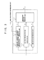
- Fig.2 shows a block diagram of the printer 100 having the image processing device 106 of the present invention.
- the printer 100 includes a frame memory 101, the image processing device 106, and an output device 102 which is an engine for printing an electronic photographic image.
- the image processing device 106 includes an image-area-separation processing unit 103 for binary images, an outline-correction processing unit 104, a multi-value processing unit 105 for pseudo-multi-value processing and multi-value gray-scale processing, and a selection unit 107.
- the image processing unit 106 is provided inside the printer 100.
- the present invention is not limited to this configuration, and can be used in various devices relating to image processing.
- the selection unit 107 selects an output of the multi-value processing unit 105 for areas which are identified as a photographic image or a graphic image by the image-area-separation processing unit 103. Also, the selection unit 107 selects an output of the outline-correction processing unit 104 for other areas. These selected outputs are provided for the output device 102.
- the image processing device 106 operates in synchronism with the output device 102 so as to process a data flow from the frame memory 101 to the output device 102.
- the image processing device 106 does not impede and slow down the printing of images stored in the frame memory 101.
- the image processing device 106 does not carry out an image-area-identification process in the manner that an online recognition process does, i.e., creating a histogram after the processing of the entire image.
- the process of the image processing device 106 can be significantly faster than that of the online recognition process.
- the frame memory 101 in the present invention stores only a binary image without any auxiliary data.
- the present invention can be embodied at a lower cost incurred for the frame memory when compared to a method requiring identification information stored in a frame memory.
- the frame memory 101 stores a binary image to be printed, and is not limited to a frame memory provided inside the printer 100 such as a laser printer.
- a frame memory provided inside the printer 100 such as a laser printer.
- it can be a page memory of a page printer, VRAM for a CRT of a computer, or a binary image file stored in an optical disk.
- Fig.3 shows a block diagram of the image-area-separation processing unit 103.
- a graphic image or a photographic image is categorized into two groups according to the number of (black) lines existing in a length of one inch.
- One group is a graphic or photographic image which is comprised of a small number of lines, and the other group is that which is comprised of a large number of lines.
- a graphic image or a photographic image comprised of a small number of lines cannot be distinguished from a screened dot pattern used for depicting letters and line-drawing.
- the image-area separation processing unit 103 tries to detect only a halftone image having a large number of lines (e.g, more than 100 lines per inch). However, the lower limit of this number can be changed, as will be described later.
- the image-area-separation processing unit 103 includes a highlight/shadow-portion-detection processing unit 110, a line-number-detection processing unit 111, a halftone-portion-detection processing unit 112, an area-detection processing unit 113, and a comprehensive-detection processing unit 114.
- the highlight/shadow-portion-detection processing unit 110 and the line-number-detection processing unit 111 operate together to tentatively extract graphic or photographic image areas comprised of a large number of lines.
- the halftone-portion-detection processing unit 112 detects areas comprised of letters, line drawings, and graphic images or photographic images having a small number of lines.
- the area-detection processing unit 113 detects areas comprised of letters, line drawings, graphic images, and photographic images.
- the comprehensive-detection processing unit 114 receives detection signals A, B, and C from the line-number-detection processing unit 111, the halftone-portion-detection processing unit 112, the area-detection processing unit 113, respectively.
- the comprehensive-detection processing unit 114 detects graphic or photographic image areas comprised of a large number of lines, and generates a detection signal A'. The processing of these processing units will be described below.
- isolated dots can be found in graphic or photographic image areas. Accordingly, the isolated dots can be used for distinguishing graphic or photographic image areas from letters or line drawings. Also, the larger the number of lines within a given length, the more the isolated dots can be found in a given size of a graphic or photographic image area. Thus, the number of isolated dots in the given area size can be used as an indicator for distinguishing graphic or photographic image areas comprised of a large number of lines from those comprised of a small number of lines.
- the highlight/shadow-portion-detection processing unit 110 detects the isolated dots so as to extract a highlight (bright) portion and a shadow (dark) portion of graphic or photographic image areas. Then, the line-number-detection processing unit 111 counts the number of the isolated dots so as to extract a shadow portion of graphic or photographic image areas, i.e., a portion comprised of a large number of lines. When graphic or photographic image areas having a large number of lines are detected, the line-number-detection processing unit 111 generates the detection signal A represented by the binary "1". The graphic or photographic image areas having a large number of lines are detected only tentatively at this stage, so that these areas may be called tentative shadow areas. The final decision is made by the comprehensive-detection processing unit 114, as will be described later.
- Figs.4A and 4B show matching patterns for detecting isolated dots.
- templates (matching patterns) as shown in Figs.4A and 4B are matched with a 3 x 3 area of an image.
- the detected isolated dots are counted within an area of a predetermined size, for example, a 9 x 9 pixel area. Then, the number of isolated dots Sx is compared with a threshold value Tk. If Sx is no smaller than Tk, a center pixel of the 9 x 9 pixel area is detected as a pixel of the graphic or photographic image areas comprised of a large number of lines.
- the threshold value Tk is dynamically changed while the 9 x 9 pixel area is moved over the image.
- the threshold value Tk is initially set to 5, for example, and can be changed according to conditions set forth in Fig.4C. In doing so, the criterion to detect the graphic or photographic image areas can be changed dynamically.
- the dynamic changes in the threshold value Tk as shown in Fig.4C can increase the probability of detecting an image area of one sort around an image area of the same sort. For example, the threshold value Tk is lowered at a given position when Sx is greater than the threshold value Tk by more than one, i.e., when a pixel at that position is definitely a pixel of a graphic or photographic image area having a large number of lines. Because the threshold value Tk is lowered, a pixel at the next position is more likely to be detected as the graphic or photographic image areas having a large number of lines. Likewise, the threshold value Tk is raised at a given position when a pixel at that position is not a pixel of a graphic or photographic image area having a large number of lines. Thus, a pixel at the next position is more likely to be detected as a continuation of the area of the same type.
- the threshold value Tk may be set externally instead, depending on a quality of an original image or on the purpose of printing.
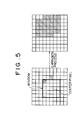
- Pixels detected as a graphic or photographic image area having a large number of lines are subject to an expansion process using a window of a predetermined size.
- This expansion process is shown in Fig.5, where the window has a size of 5 x 5 pixels as an example.
- the window is moved over an image comprised of detected pixels (shown as black pixels) and pixels which are not detected (shown as white pixels).
- the center pixel of the window is also regarded as a detected pixel.
- the dynamic changes in the threshold value Tk and the expansion process described above ensures that the detected pixels tend to be clustered rather than to be isolated from each other. Thus, the detection of image areas can be prevented from becoming too sensitive to a small fluctuation of the number of lines.
- Images stored in an optical disk or images sent via a facsimile can have isolated dots around letters or line drawings, because multi-valued images scanned by the scanner 600 are converted into binary images.
- the isolated dots around letters or line drawings are fewer than those of graphic or photographic image areas.
- the isolated dots are not detected as pixels of graphic or photographic image areas.
- Figs.6A through 6L show examples of matching patterns for finding chunks of black pixels or white pixels. By matching these matching patterns with the input binary image, the chunks which have the same arrangement as those of the matching patterns can be detected. Then, each detected pixel is subject to the expansion process described earlier.
- halftone areas of the input binary image which include letters, line drawings, and graphic or photographic image areas of a small number of lines.
- the halftone-portion-detection processing unit 112 When the letters, the line drawings, and the graphic or photographic image areas are detected, the halftone-portion-detection processing unit 112 generates the detection signal B represented by the binary "1".
- the area-detection processing unit 113 detects areas which are comprised of either letters, line-drawings, graphics, or photographic images. In other words, the area-detection processing unit 113 excludes background areas, which are defined as any blank area, so as to detect non-background area.
- Detection of the areas is realized by the expansion process described with reference to Fig.5.
- an image input to the area-detection processing unit 113 is not the image of detected pixels, but is the binary image provided for the image processing unit 106.
- the expansion process at the area-detection processing unit 113 is meant to expand black pixels to generate large chunks of black pixels covering the areas other than the background.
- the comprehensive-detection processing unit 114 detects the shadow areas, i.e., graphic or photographic image areas comprised of a large number of lines, based on the detection signals A, B, and C.
- a comprehensive assessment of the detection signals A, B, and C can enhance the reliability of the detection of graphic or photographic image areas having a large number of lines.
- the pertinent pixel belongs to the tentative shadow areas, i.e., areas which are likely to be the shadow areas.
- the detection signal B is "1”
- the pertinent pixel belongs to the halftone areas, i.e., areas which include letters, line-drawings, and highlight graphic or highlight photographic image areas.
- the halftone areas are supposed to be areas other than the shadow area and the background area.
- the detection signal C is "1”
- the pertinent pixel belongs to the non-background areas, i.e., areas which include letters, line-drawings, and graphic or photographic image areas.
- the comprehensive-detection processing unit 114 detects a pixel for which C is equal to 1 and either A is equal to 1 or B is equal to 0. Then, the comprehensive-detection processing unit 114 generates the detection signal A' as a binary "1" for the detected pixel.
- the detection signal A' of "1" indicates that this pixel belongs to a graphic or photographic image area having a large number of lines.
- a binary image is preferably created by the error diffusion process which preserves densities of an image scanned by the scanner.
- Fig.7 shows such a configuration, in which the scanner 600 scans an image, and the scanned image is converted into a binary image by an error-diffusion processing unit 120. The binary image is then subject to the processing of the image processing unit 106.
- halftone-screen processing is used for converting an image into a binary image in a printer 100 such as a laser printer.
- a printer 100 such as a laser printer.
- the error-diffusion processing which preserves densities is used in light of the fact described above.
- the outline-correction processing unit 104, the multi-value processing unit 105, and the selection unit 107 of Fig.2 will now be described below.
- the outline-correction processing carried out by the outline-correction processing unit 104 is similar to the RET method of the Hewlett-Packard Co..
- a 7 x 11 pixel template is used in template matching for detecting jagged edges of letters and line drawings. Then, binary pixels around the detected jagged edges are converted and printed in multi-values, so that the printed edges visually appear to be less jagged.
- this process has a harmful effect on photographic or graphic images.
- the outline-correction processing is applied to photographic or graphic images comprised of a small number of lines as well as letters and line drawings. Thus, no harmful effect is inflicted.
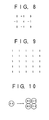
- the multi-value processing unit 105 first applies a Laplacian filter shown in Fig.8 to a binary image.
- a Laplacian filter shown in Fig.8
- an output image of the Laplacian filter has a large pixel value around edge portions of the input image, and has small pixel values in portions of gradual level changes.
- the multi-value processing unit 105 applies an averaging filter shown in Fig.9 to the binary image to generate a multi-valued image. Since sharpness of the edges should be preserved as much as possible, the averaging filter should have a small size around the edges. In consideration of this, the multi-value processing unit 105 changes a size of the averaging filter according to the magnitude of the Laplacian filter output. That is, when the averaging filter is applied in order to generate the multi-valued image, the size of the averaging filter is decreased as the magnitude of the Laplacian filter output increases.
- This process of generating the multi-valued image is referred to as the pseudo-multi-value processing, and the multi-valued image thus generated is referred to as a pseudo-multi-valued image.
- the multi-value processing unit 105 applies a multi-value gray-scale process such as a 2 x 2 multi-value dither process.
- a multi-value gray-scale process such as a 2 x 2 multi-value dither process.
- the output device 102 of Fig.2 is assumed to be capable of outputting a multi-valued image
- a 2 x 2 matrix of multi-valued pixels is assumed to be a unit for representing a gray scale.
- the pseudo-multi-valued image created by the pseudo-multi-value processing is subject to the 2 x 2 multi-value dither process.
- the 2 x 2 multi-value dither process assigns possible output levels of the output device to each pixel, such that the 2 x 2 matrix has a gray level approximately representing a value of a corresponding portion of the pseudo-multi-valued image.
- the multi-value gray-scale process can be a binary halftone process using finer lines or an error-diffusion process, instead of the multi-value dither process.
- the multi-value gray-scale process can be omitted.
- Images received via a facsimile are typically represented at 200 DPI.
- a width and a length of the images should be enlarged by a factor of 2.
- jagged edges of letters and line drawings in facsimile images are generally removed by a smoothing process.
- SPC method, the logical sum method, and the projection method are applied to facsimile images, photographic or graphic images tend to become coarse pictures having a degraded image quality.
- the multi-value processing unit 105 enlarges the size of pseudo-multi-valued photographic images by a factor of 2. This is done by applying a simple enlargement method of enlarging 1 pixel into 2 x 2 pixels of the same values, as shown in Fig.10. This can improve the image quality of photographic images and the like.
- the selection unit 107 receives the detection signal A' from the image-area-separation processing unit 103.
- the detection signal A' is equal to 1
- the current pixel is a pixel of a graphic or photographic image area having a large number of lines.
- the selection unit 107 selects the output of multi-value processing unit 105.
- the detection signal A' is equal to 0
- the current pixel is not a pixel of a graphic or photographic image area having a large number of lines.
- the selection unit 107 selects the output of the outline-correction processing unit 104.
- the printer provided with the image processing unit 106 can print out the multi-valued image of an improved image quality while eliminating the jagged edges of letters and line drawings.
- Fig.11 shows a variation of the printer having the image processing devices of the present invention.
- the image processing device of the present invention is applied to binary black-and-white images.
- each color component is treated as a binary color image. Namely, four colors of yellow, magenta, cyan, and black are used in color printing. Binary data for these colors is stored in frame memories 101Y, 101M, 101C, and 101B, respectively.
- Image processing units 106Y, 106M, 106C, and 106B carry out the binary-to-multi-value processing in the same way as that of the previous embodiment. Then, outputs of the image processing units 106Y, 106M, 106C, and 106B are provided for the color output device 210.
- an image processing device 106' which does not include the outline-correction processing unit may be used as the image processing devices 106Y, 106M, and 106C.
- the image processing device 106 of Fig.2 may be used as the image processing unit 106B1 to perform the outline processing only on black pixels. In this case, jagged edges of color letters and color line drawings cannot be eliminated. However, this configuration of the image processing device can be implemented at a lower cost.
- the photographic or graphic images comprised of a relatively large number of lines are made into multi-valued images by using filters, so that the photographic or graphic images comprised of the relatively large number of lines can be represented in gray levels. Also, only image areas other than the photographic or graphic image areas having the relatively large number of lines are subject to the outline-correction processing for correcting the jagged edges. Thus, the outline-correction processing can be prevented from having a harmful effect on the photographic or graphic image areas having a relatively large number of lines.
- the multi-value processing and the outline-correction processing are performed in realtime on data flow between the memory storage for a binary image and the multi-value output device.
- a binary image can be converted into a multi-valued image without slowing printing speed.
- the photographic or graphic image areas comprised of a relatively small number of lines, as well as letters and line drawings, are subject to the outline-correction processing.
- an image quality of the photographic or graphic image areas comprised of a relatively small number of lines can be prevented from degrading.
- the threshold value which is used for detecting high-shadow portions of the photographic or graphic images can be set externally.
- the threshold value can be set to a larger value in order to prevent erroneous image-area separation.
- images which are made into multi-valued images are enlarged by a given factor.
- the SPC method, the logical sum method, the projection method, and the like can be prevented from degrading an image quality in the photographic or graphic image areas.
- images having multi-values are converted into binary images by using the error diffusion process which preserves image densities.
- the gray-level representation of the reconstructed multi-valued images can be enhanced.
- the image processing device of the present invention can be provided for each color component in a color printer.
- jagged edges of letters and line drawings in color images can be removed, and, at the same time, the gray-scale representation of the photographic or graphic image areas can be enhanced.
- the outline-correction processing can be conducted only for the black component among various color components.
- jagged edges of letters and line drawings can be removed with a low cost incurred on the implementation of the image processing device.
Landscapes
- Engineering & Computer Science (AREA)
- Multimedia (AREA)
- Signal Processing (AREA)
- Facsimile Image Signal Circuits (AREA)
- Image Processing (AREA)
Claims (17)
- Dispositif de traitement d'image (106) pour convertir une image binaire en une image de sortie de valeurs multiples, ledit dispositif de traitement d'image (106) comprenant :
une unité de traitement de séparation de zones d'image (103) et une unité de sélection (107) ;
caractérisé en ce que :ladite unité de traitement de séparation de zones d'image (103) détecte des zones d'ombre dans ladite image binaire, lesdites zones d'ombre étant au moins une zone prise parmi une zone d'image graphique et une zone d'image photographique comprenant des lignes d'image, un certain nombre desdites lignes d'image existant par longueur unitaire, lequel nombre étant supérieur à un nombre prédéterminé ;une unité de traitement de correction de contour (104) corrige des bords en escalier dans ladite image binaire afin de générer une image correcte, les bords en escalier étant sensiblement éliminés ;une unité de traitement de valeurs multiples (105) convertit ladite image binaire en une image de valeurs multiples à l'aide d'une application de filtre ; etladite unité de sélection (107) sélectionne ladite image de valeurs multiples pour lesdites zones d'ombre et ladite image corrigée pour des zones autres que lesdites zones d'ombre de façon à générer ladite image de sortie de valeurs multiples. - Dispositif de traitement d'image (106) selon la revendication 1, caractérisé en outre en ce que lesdites zones autres que lesdites zones d'ombre incluent des zones de lettres, des zones de dessin de ligne, des zones d'image graphique définies par un certain nombre de lignes qui est inférieur audit nombre prédéterminé desdites lignes, et des zones d'image photographique définies par un certain nombre de lignes qui est inférieur audit nombre prédéterminé desdites lignes.
- Dispositif de traitement d'image (106) selon la revendication 1, caractérisé en outre en ce que ladite unité de traitement de séparation de zones d'image (103) comprend :une unité de détection de zone d'ombre (110, 111) qui détecte des zones d'ombre de tentative qui coïncident sensiblement avec lesdites zones d'ombre ;une unité de détection de zone en demi-teinte (112) qui détecte des zones en demi-teinte, lesdites zones en demi-teinte incluant des zones de lettres, des zones de dessin de ligne, au moins une zone prise parmi des zones d'image graphique et des zones d'image photographique définies par un certain nombre de lignes qui est inférieur audit nombre prédéterminé desdites lignes, et au moins une zone prise parmi des zones d'image graphique et photographique définies par un certain nombre de lignes égal audit nombre prédéterminé desdites lignes ;une unité de détection de zone (113) qui détecte des zones de non arrière-plan, lesdites zones de non arrière-plan incluant lesdites zones de lettre, lesdites zones de dessin de ligne, lesdites zones d'image graphique et lesdites zones d'image photographique ; etune unité de détection de compréhension (114) qui détecte lesdites zones d'ombre en sélectionnant lesdites zones de non arrière-plan qui appartiennent à au moins une zone prise parmi lesdites zones d'ombre de tentative et des zones autres que lesdites zones en demi-teinte.
- Dispositif de traitement d'image (106) selon la revendication 3, caractérisé en outre en ce que ladite unité de détection de zone d'ombre (110, 111) comprend :une unité de détection de partie éclairée/d'ombre (110) qui détecte des points isolés dans ladite image binaire afin de détecter ladite au moins une desdites zones d'images graphique et de photographie ; etune unité de détection de nombre de lignes (111) qui détecte lesdites zones d'ombre de tentative en trouvant un pixel avec une zone d'entourage d'une taille prédéterminée qui inclut un certain nombre de points isolés, ledit nombre étant supérieur à une valeur de seuil.
- Dispositif de traitement d'image (106) selon la revendication 4, caractérisé en outre en ce que ladite valeur de seuil est modifiée dynamiquement en fonction d'une position dudit pixel dans ladite image binaire, de telle sorte que lesdites zones d'ombre de tentative tendent à être groupées.
- Dispositif de traitement d'image (106) selon la revendication 4, caractérisé en outre en ce que ladite valeur de seuil est établie de façon externe.
- Dispositif de traitement d'image (106) selon la revendication 3, caractérisé en outre en ce que ladite unité de détection de zone en demi-teinte (112) détecte lesdites zones en demi-teinte en trouvant des tronçons d'au moins un pixel pris parmi des pixels noirs et des pixels blancs, lesquels tronçons présentent une taille supérieure à une taille de tronçon prédéterminée.
- Dispositif de traitement d'image (106) selon la revendication 3, caractérisé en ce que ladite unité de détection de zone (113) détecte lesdites zones de non arrière-plan en étendant des pixels noirs de ladite image binaire à l'intérieur d'une fenêtre d'une taille de fenêtre prédéterminée.
- Dispositif de traitement d'image (106) selon la revendication 1, caractérisé en ce que ladite unité de traitement de valeurs multiples (105) agrandit en outre ladite image de valeurs multiples selon un facteur prédéterminé.
- Dispositif de traitement d'image (106) selon la revendication 3, caractérisé en ce que ladite image binaire est une image créée par une technique de diffusion d'erreurs à partir d'une image de valeurs multiples originale.
- Agencement de traitement d'image (106Y, 106M, 106C, 106B1) pour une image couleur formée à partir d'images binaires couleur dont chacune est dans une composante de couleur correspondante, ledit traitement d'image comprenant, pour chaque image binaire couleur, un dispositif de traitement d'image tel que revendiqué dans la revendication 1.
- Agencement de traitement d'image (106Y, 106M, 106C, 106B1) selon la revendication 11, caractérisé en outre en ce que ladite unité de traitement de correction de contour (104) est prévue seulement pour une composante de couleur noire.
- Dispositif de traitement d'image selon l'une quelconque des revendications 1 à 10, caractérisé en outre en ce qu'il comprend :une mémoire (101) pour stocker une image binaire ; etun dispositif de sortie (102) pour imprimer ladite image de sortie.
- Dispositif de traitement d'image (100) selon la revendication 13, caractérisé en outre en ce que ladite unité de traitement de séparation de zones d'image (103), ladite unité de traitement de correction de contour (104), ladite unité de traitement de valeurs multiples (105) et ladite unité de sélection (107) opèrent en synchronisation avec ledit dispositif de sortie (102).
- Agencement de traitement d'image selon la revendication 11 ou 12, caractérisé en outre en ce qu'il comprendune mémoire (101Y, 101M, 101C, 101B1) pour stocker des images binaires couleur formant une image couleur, chacune des dites images binaires couleur comprenant une composante couleur correspondante ; etun dispositif de sortie (210) pour imprimer une image couleur de valeurs multiples en utilisant des images de sortie dont chacune est ladite image de sortie de ladite composante couleur correspondante.
- Dispositif de traitement d'image (106) selon la revendication 1, caractérisé en outre en ce que lesdites zones autres que lesdites zones d'ombre incluent des zones de lettre, des zones de dessin de ligne, des zones d'image graphique définies par un certain nombre de lignes égal audit nombre prédéterminé desdites lignes et des zones d'image photographiques définies par un certain nombre de lignes égal audit nombre prédéterminé desdites lignes.
- Dispositif de traitement d'image (106) selon la revendication 13, caractérisé en outre en ce que lesdites zones autres que lesdites zones d'ombre incluent des zones de lettre, des zones de dessin de ligne, des zones d'image graphique définies par un certain nombre de lignes égal audit nombre prédéterminé desdites lignes et des zones d'image photographiques définies par un certain nombre de lignes égal audit nombre prédéterminé desdites lignes.
Applications Claiming Priority (6)
| Application Number | Priority Date | Filing Date | Title |
|---|---|---|---|
| JP9216094 | 1994-04-28 | ||
| JP9216094 | 1994-04-28 | ||
| JP92160/94 | 1994-04-28 | ||
| JP93428/95 | 1995-04-19 | ||
| JP9342895 | 1995-04-19 | ||
| JP7093428A JPH0818785A (ja) | 1994-04-28 | 1995-04-19 | 画像出力装置 |
Publications (3)
| Publication Number | Publication Date |
|---|---|
| EP0680194A2 EP0680194A2 (fr) | 1995-11-02 |
| EP0680194A3 EP0680194A3 (fr) | 1996-11-27 |
| EP0680194B1 true EP0680194B1 (fr) | 1999-12-01 |
Family
ID=26433630
Family Applications (1)
| Application Number | Title | Priority Date | Filing Date |
|---|---|---|---|
| EP95106333A Expired - Lifetime EP0680194B1 (fr) | 1994-04-28 | 1995-04-27 | Dispositif de traitement d'images et dispositif de sortie d'images pour la conversion d'une image binaire en une image à valeurs multiples |
Country Status (4)
| Country | Link |
|---|---|
| US (1) | US5995658A (fr) |
| EP (1) | EP0680194B1 (fr) |
| JP (1) | JPH0818785A (fr) |
| DE (1) | DE69513560T2 (fr) |
Families Citing this family (7)
| Publication number | Priority date | Publication date | Assignee | Title |
|---|---|---|---|---|
| US5987221A (en) * | 1997-01-24 | 1999-11-16 | Hewlett-Packard Company | Encoded orphan pixels for discriminating halftone data from text and line art data |
| JPH11232378A (ja) * | 1997-12-09 | 1999-08-27 | Canon Inc | デジタルカメラ、そのデジタルカメラを用いた文書処理システム、コンピュータ可読の記憶媒体、及び、プログラムコード送出装置 |
| US6633411B1 (en) * | 1998-04-01 | 2003-10-14 | International Business Machines Corporation | Method and apparatus for repurposing binary images |
| JP3907155B2 (ja) * | 2000-09-04 | 2007-04-18 | 株式会社リコー | 画像データ補正装置,画像読取り装置および画像形成装置 |
| JP2002262078A (ja) * | 2001-03-02 | 2002-09-13 | Minolta Co Ltd | 画像処理装置及び画像形成装置 |
| JP2003348342A (ja) * | 2002-02-28 | 2003-12-05 | Ricoh Co Ltd | 画像処理装置及び画像形成装置 |
| JP4006411B2 (ja) * | 2004-03-26 | 2007-11-14 | キヤノン株式会社 | 画像形成装置及び方法 |
Family Cites Families (15)
| Publication number | Priority date | Publication date | Assignee | Title |
|---|---|---|---|---|
| US4110795A (en) * | 1976-12-20 | 1978-08-29 | Litton Systems, Inc. | Method of graphic data redundancy reduction in an optical facsimile system |
| US4194221A (en) * | 1978-12-26 | 1980-03-18 | Xerox Corporation | Automatic multimode continuous halftone line copy reproduction |
| NL8503558A (nl) * | 1985-12-24 | 1987-07-16 | Oce Nederland Bv | Werkwijze en inrichting voor het herkennen van halftoon beeldinformatie. |
| EP0506148B1 (fr) * | 1986-08-29 | 1999-10-27 | Canon Kabushiki Kaisha | Dispositif d'entrée et de sortie et procédé pour traiter des données d'images |
| US4926251A (en) * | 1987-04-07 | 1990-05-15 | Kabushiki Kaisha Toshiba | Color image processing apparatus with image corrector |
| JPH01198870A (ja) * | 1987-10-08 | 1989-08-10 | Ricoh Co Ltd | デジタルカラー画像処理装置 |
| US4847641A (en) * | 1988-08-16 | 1989-07-11 | Hewlett-Packard Company | Piece-wise print image enhancement for dot matrix printers |
| JPH02165775A (ja) * | 1988-12-20 | 1990-06-26 | Toshiba Corp | 画像処理装置 |
| US5131049A (en) * | 1989-12-08 | 1992-07-14 | Xerox Corporation | Identification, characterization, and segmentation of halftone or stippled regions of binary images by growing a seed to a clipping mask |
| DE69123991T2 (de) * | 1990-03-23 | 1997-05-22 | Canon Kk | Bildverarbeitung mit neuronalem Netzwerk |
| JPH04330864A (ja) * | 1991-05-02 | 1992-11-18 | Minolta Camera Co Ltd | 画像処理装置 |
| US5459587A (en) * | 1991-05-02 | 1995-10-17 | Minolta Camera Kabushiki Kaisha | Processing apparatus capable of discriminating between pseudo half-tone/non-half-tone image data based upon the number of adjacencies of similar type of pixels within a block |
| JPH0591313A (ja) * | 1991-09-27 | 1993-04-09 | Minolta Camera Co Ltd | フアクシミリ装置 |
| US5701363A (en) * | 1993-06-18 | 1997-12-23 | Ricoh Company, Ltd. | Binary to multi-value conversion apparatus for improved image reduction and enlargement |
| JP3636332B2 (ja) * | 1993-12-24 | 2005-04-06 | セイコーエプソン株式会社 | 画像処理方法および画像処理装置 |
-
1995
- 1995-04-19 JP JP7093428A patent/JPH0818785A/ja active Pending
- 1995-04-27 DE DE69513560T patent/DE69513560T2/de not_active Expired - Fee Related
- 1995-04-27 EP EP95106333A patent/EP0680194B1/fr not_active Expired - Lifetime
-
1997
- 1997-05-12 US US08/854,748 patent/US5995658A/en not_active Expired - Fee Related
Also Published As
| Publication number | Publication date |
|---|---|
| EP0680194A2 (fr) | 1995-11-02 |
| EP0680194A3 (fr) | 1996-11-27 |
| DE69513560T2 (de) | 2000-04-27 |
| US5995658A (en) | 1999-11-30 |
| DE69513560D1 (de) | 2000-01-05 |
| JPH0818785A (ja) | 1996-01-19 |
Similar Documents
| Publication | Publication Date | Title |
|---|---|---|
| US6137907A (en) | Method and apparatus for pixel-level override of halftone detection within classification blocks to reduce rectangular artifacts | |
| EP1154634B1 (fr) | Procédé et système de correction de la translucidité d'image pour la duplication d'images | |
| US6157736A (en) | Method and apparatus for automatic image segmentation using template matching filters | |
| US7684085B2 (en) | Methods and apparatus for reconstructing digitized images | |
| KR100477656B1 (ko) | 디지털 화질 개선 방법 및 장치 | |
| US7411699B2 (en) | Method and apparatus to enhance digital image quality | |
| US6834124B1 (en) | Adaptive image enhancement filter | |
| EP0892549A3 (fr) | Procédé et appareil de reproduction d'une image avec impression de niveaux de gris | |
| US6078697A (en) | Method and apparatus for segmenting image data into contone, text and halftone classifications | |
| US6775031B1 (en) | Apparatus and method for processing images, image reading and image forming apparatuses equipped with the apparatus, and storage medium carrying programmed-data for processing images | |
| US5754684A (en) | Image area discrimination apparatus | |
| US20100046856A1 (en) | Method for binary to contone conversion with non-solid edge detection | |
| US7145694B2 (en) | Image processing apparatus and method | |
| EP0680194B1 (fr) | Dispositif de traitement d'images et dispositif de sortie d'images pour la conversion d'une image binaire en une image à valeurs multiples | |
| JP3073837B2 (ja) | 画像領域分離装置及び画像領域分離方法 | |
| JP3423665B2 (ja) | 領域判別方法および装置 | |
| JP4084537B2 (ja) | 画像処理装置、画像処理方法および記録媒体並びに画像形成装置 | |
| CA2215555C (fr) | Dispositif de traitement d'images | |
| JPH02199588A (ja) | 像域識別装置 | |
| JP3070884B2 (ja) | 2値画像識別装置 | |
| JP3146517B2 (ja) | 画像処理装置 | |
| JP3183788B2 (ja) | 網点領域判定装置 | |
| JPH01173971A (ja) | 画像処理方法 | |
| JPH07121063B2 (ja) | 画像処理装置 | |
| Yi et al. | Document image enhancement algorithm for digital color copier |
Legal Events
| Date | Code | Title | Description |
|---|---|---|---|
| PUAI | Public reference made under article 153(3) epc to a published international application that has entered the european phase |
Free format text: ORIGINAL CODE: 0009012 |
|
| 17P | Request for examination filed |
Effective date: 19950427 |
|
| AK | Designated contracting states |
Kind code of ref document: A2 Designated state(s): DE FR GB IT |
|
| PUAL | Search report despatched |
Free format text: ORIGINAL CODE: 0009013 |
|
| AK | Designated contracting states |
Kind code of ref document: A3 Designated state(s): DE ES FR GB IT |
|
| 17Q | First examination report despatched |
Effective date: 19980901 |
|
| GRAG | Despatch of communication of intention to grant |
Free format text: ORIGINAL CODE: EPIDOS AGRA |
|
| GRAG | Despatch of communication of intention to grant |
Free format text: ORIGINAL CODE: EPIDOS AGRA |
|
| GRAG | Despatch of communication of intention to grant |
Free format text: ORIGINAL CODE: EPIDOS AGRA |
|
| GRAH | Despatch of communication of intention to grant a patent |
Free format text: ORIGINAL CODE: EPIDOS IGRA |
|
| RBV | Designated contracting states (corrected) |
Designated state(s): DE FR GB IT |
|
| GRAH | Despatch of communication of intention to grant a patent |
Free format text: ORIGINAL CODE: EPIDOS IGRA |
|
| GRAA | (expected) grant |
Free format text: ORIGINAL CODE: 0009210 |
|
| ITF | It: translation for a ep patent filed | ||
| AK | Designated contracting states |
Kind code of ref document: B1 Designated state(s): DE FR GB IT |
|
| REF | Corresponds to: |
Ref document number: 69513560 Country of ref document: DE Date of ref document: 20000105 |
|
| ET | Fr: translation filed | ||
| PLBE | No opposition filed within time limit |
Free format text: ORIGINAL CODE: 0009261 |
|
| STAA | Information on the status of an ep patent application or granted ep patent |
Free format text: STATUS: NO OPPOSITION FILED WITHIN TIME LIMIT |
|
| 26N | No opposition filed | ||
| PGFP | Annual fee paid to national office [announced via postgrant information from national office to epo] |
Ref country code: FR Payment date: 20010409 Year of fee payment: 7 |
|
| PGFP | Annual fee paid to national office [announced via postgrant information from national office to epo] |
Ref country code: DE Payment date: 20010423 Year of fee payment: 7 |
|
| PGFP | Annual fee paid to national office [announced via postgrant information from national office to epo] |
Ref country code: GB Payment date: 20010425 Year of fee payment: 7 |
|
| REG | Reference to a national code |
Ref country code: GB Ref legal event code: IF02 |
|
| PG25 | Lapsed in a contracting state [announced via postgrant information from national office to epo] |
Ref country code: GB Free format text: LAPSE BECAUSE OF NON-PAYMENT OF DUE FEES Effective date: 20020427 |
|
| PG25 | Lapsed in a contracting state [announced via postgrant information from national office to epo] |
Ref country code: DE Free format text: LAPSE BECAUSE OF NON-PAYMENT OF DUE FEES Effective date: 20021101 |
|
| GBPC | Gb: european patent ceased through non-payment of renewal fee |
Effective date: 20020427 |
|
| PG25 | Lapsed in a contracting state [announced via postgrant information from national office to epo] |
Ref country code: FR Free format text: LAPSE BECAUSE OF NON-PAYMENT OF DUE FEES Effective date: 20021231 |
|
| REG | Reference to a national code |
Ref country code: FR Ref legal event code: ST |
|
| PG25 | Lapsed in a contracting state [announced via postgrant information from national office to epo] |
Ref country code: IT Free format text: LAPSE BECAUSE OF NON-PAYMENT OF DUE FEES;WARNING: LAPSES OF ITALIAN PATENTS WITH EFFECTIVE DATE BEFORE 2007 MAY HAVE OCCURRED AT ANY TIME BEFORE 2007. THE CORRECT EFFECTIVE DATE MAY BE DIFFERENT FROM THE ONE RECORDED. Effective date: 20050427 |