EP0680200A2 - Bildanzeigeverfahren - Google Patents
Bildanzeigeverfahren Download PDFInfo
- Publication number
- EP0680200A2 EP0680200A2 EP95302790A EP95302790A EP0680200A2 EP 0680200 A2 EP0680200 A2 EP 0680200A2 EP 95302790 A EP95302790 A EP 95302790A EP 95302790 A EP95302790 A EP 95302790A EP 0680200 A2 EP0680200 A2 EP 0680200A2
- Authority
- EP
- European Patent Office
- Prior art keywords
- image
- data
- display
- version
- type
- Prior art date
- Legal status (The legal status is an assumption and is not a legal conclusion. Google has not performed a legal analysis and makes no representation as to the accuracy of the status listed.)
- Ceased
Links
Images





Classifications
-
- H—ELECTRICITY
- H04—ELECTRIC COMMUNICATION TECHNIQUE
- H04N—PICTORIAL COMMUNICATION, e.g. TELEVISION
- H04N1/00—Scanning, transmission or reproduction of documents or the like, e.g. facsimile transmission; Details thereof
- H04N1/46—Colour picture communication systems
- H04N1/56—Processing of colour picture signals
- H04N1/60—Colour correction or control
- H04N1/6011—Colour correction or control with simulation on a subsidiary picture reproducer
Definitions
- the present invention relates to image presentation techniques.
- Norris et al., US-A 4,656,524, describe an electronic imaging copier for making enhanced photographic copies of types of photographs.
- An object of the present invention is to alleviate problems associated with visualizing how a specific device operating in a particular way would present an image.
- the invention deals with a basic problem in preparing an image for presentation.
- the image could be presented by a variety of different types of image output devices, including various types of printers, displays, and so forth.
- a "type of image output devices" is a set of similarly structured image output devices, each of which responds to data defining an image by performing substantially the same operations so that the image is presented in substantially the same way.
- An image presented by a properly functioning image output device of a type should be perceptible as substantially identical to the same image presented by other properly functioning image output devices of the same type, subject to uncontrolled variations between devices such as wear and tear, temperature, humidity, toner composition, and so forth.
- Devices of each type can typically present an image in numerous ways, with variations in brightness and darkness, in contrast, in paper color or size, and so forth.
- the appearance of the image may differ substantially depending on which type of devices presents it and how devices of that type operate in making the presentation.
- a human preparing the image for presentation may find it difficult or impossible to view the image presented by a specific type of image output devices operating in a particular way and may therefore be unable to visualize the image as it would be presented by devices of that type operating in that way.
- the invention provides a group of techniques that alleviate the problem of visualizing how a specific device operating in a particular way would present an image.
- the techniques employ a display with sufficient resolution to present images as they would appear when presented on another type of image output devices.
- Each technique uses data defining a starting image to obtain data defining a version of the starting image that can be presented on the display to show the starting image as it would appear when presented by an image output device of another type.
- Each technique provides the data defining the version to the display so that the display presents the version of the starting image, showing the starting image as it would appear when presented by an image output device of the other type.
- a first technique allows a user to indicate a type of image output devices; in response, the first technique presents an image on a display as the image would appear when presented by a device of the indicated type.
- a second technique allows a user to indicate a change in a user-changeable parameter of a type of image output devices; in response, the second technique presents an image on a display as the image would appear when presented by a device of the indicated type with the changed parameter.
- Third and fourth techniques present a version of an image on an image output device that appears substantially identical to a displayed version of the image: The third technique uses the data defining the image from which the displayed image was obtained. The fourth technique uses the data defining the displayed version of the image. Both the third and fourth techniques obtain data defining another version that can be presented on the device and that has a substantially identical appearance when presented as the displayed image.
- the first technique receives a signal from a user indicating a first type of image output devices.
- the first technique uses the data defining a starting image to automatically obtain device version data defining a version of the starting image as it would appear when presented by the first type of devices.
- the first technique then provides the device version data to the display, which presents the version of the starting image as it would appear when presented by the first type of devices.
- the user could indicate the first type of device in any appropriate way.
- the user could provide keystrokes indicating the first type of device.
- the user could select a menu item presented on a display.
- the user could select one of a set of buttons presented on a display.
- the first technique could be implemented iteratively so that the user could indicate a type of devices during each iteration, and each iteration would present a version for its indicated type.
- the types of image output devices can include printers and displays, including, for example, cathode ray tube (CRT) displays, liquid crystal displays (LCDs), and projectors.
- CTR cathode ray tube
- LCDs liquid crystal displays
- projectors projectors
- the second technique receives a signal from a user indicating a change in a user changeable parameter of a first type of image output devices.
- the second technique obtains changed parameter data indicating a value of the user changeable parameter resulting from the change indicated by the signal.
- the second technique automatically obtains device version data and provides the device version data to a display that presents the version of the starting image as it would appear when presented by the indicated type of device.
- the second technique uses the changed parameter data to obtain the device version data; the device version shows a version of the starting image that can be presented on the display to show the starting image as it would appear when presented by an image output device of the first type with the indicated value of the user changeable parameter.
- the system includes an image output device of the first type.
- the third and fourth techniques each automatically obtain device version data and provide the device version data to a display that presents the version of the starting image as it would appear when presented by the first type.
- the third technique uses the data defining the starting image to obtain output image data defining an output version of the starting image for presentation by the image output device; similarly, the fourth technique uses the device version data to obtain output image data defining an output version of the starting image for presentation by the image output device.
- the third and fourth techniques both provide the output image data to the image output device, which presents of a version that is substantially identical to the version presented by the display.
- Another aspect of the invention solves a problem that arises in printing an image that has been prepared using a display.
- a user can prepare an image that has a desired appearance when presented on the display, but if the user then requests that the image be printed, the resulting printed image may have a significantly different appearance than the displayed image.
- the invention solves the problem of different displayed and printed appearances by providing a technique that uses the data defining the displayed version of the image to obtain a printed version of the image that appears substantially identical to the displayed version.
- the technique employs a display with sufficient resolution to present images as they would appear when printed.
- the technique provides first version data defining a first version of an image to the display so that the first version is displayed.
- the technique also uses the first version data to obtain second version data defining a second version of the image that a printer can print to provide an appearance substantially identical to the displayed first version.
- the technique provides the second version data to the printer so that the printer prints the second version, showing the image with an appearance substantially identical to the displayed first version.
- the techniques described above can be implemented on a machine that includes memory and a processor, in addition to the display and data defining an image.
- the memory can store instructions the processor can execute to perform the techniques.
- the memory can also store transform data indicating a transform operation the processor can perform to obtain data defining a version of an image; for example, the transform data can indicate a transform operation for a type of devices.
- the memory can store default transform data indicating a default transform operation the processor can perform to obtain a default version of the starting image that is presented before the user provides a signal.
- the display can be a monochrome or color active matrix liquid crystal display (AMLCD)
- AMLCD active matrix liquid crystal display
- the machine could, for example, be a copier or a printer, and the display could be a part of the copier or printer or it could be a display of a workstation or other computer connected to the copier or printer.
- the techniques described above are advantageous compared to conventional techniques because they permit a user to overcome the problem of visualizing images and the problem of differences between displayed and printed images. Therefore, a user can iteratively view the image as it would appear when presented by several different types of devices or in several different ways. Upon finding a desired presentation, the user can cause the image to be presented.
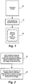
- Fig. 1 shows how data defining a starting image can be used to display a version of the image as it would appear when presented by an image output device of another type.
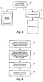
- Fig. 2 shows general acts in using data defining a starting image can be used to display a version of the image as it would appear when presented by an image output device of another type.
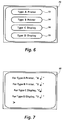
- Fig. 3 shows how display version data used to display a version of an image can be used to obtain a printed version of the image substantially identical to the displayed version.
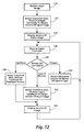
- Fig. 4 shows general acts in using display version data to obtain a printed version of an image substantially identical to the displayed version.
- Fig. 1 begins with data defining starting image 10, which could be obtained, for example, from image input circuitry.
- the data defining starting image 10 is then used to automatically obtain device version data 12.
- Device version data 12 define a version of starting image 10 that can be presented on a display to show starting image 10 as it would appear when presented by a first type of image output devices. This is possible if the display has sufficient resolution to present output images as they would appear on a first type of image output devices.
- Device version data 12 can then be provided to a display with sufficient resolution, resulting in presentation of device version 14 of starting image 10.
- Device version 14 shows starting image 10 as it would appear when presented by an image output device of the first type.
- the act in box 20 begins by using data defining a starting image to obtain device version data.
- the device version data define a device version of the starting image that can be presented on a display to show the starting image as it would appear when presented by a first type of image output devices.
- the act in box 22 then provides the device version data to a display that has sufficient resolution to present output images as they would appear on a first type of image output devices.
- the display presents the device version, showing the starting image as it would appear when presented by an image output device of the first type.
- Fig. 3 begins with display version data 30 defining a display version of an image that can be presented on display circuitry to show the image as it would appear when printed by printing circuitry.
- Display version data 30 is provided to display circuitry with sufficient resolution to present output images as they would appear when printed by the printing circuitry.
- the display circuitry presents display version 32.
- Display version data 30 is also used to obtain print version data 34, defining a print version of the image that can be printed by the printing circuitry.
- Print version data 34 is then provided to the printing circuitry, producing print version 36, which is perceptible as substantially identical to display version 32.
- the act in box 40 begins by obtaining version data defining a display version of an image that can be presented on display circuitry to show the image as it would appear when printed by printing circuitry.
- the act in box 42 then provides the display version data to display circuitry with sufficient resolution to present output images as they would appear when printed by the printing circuitry, resulting in presentation of the display version.
- the act in box 44 uses the display version data to obtain print version data defining a print version of the image that can be printed by the printing circuitry.
- the act in box 46 provides the print version data to the printing circuitry, which prints the print version, perceptible as substantially identical to the display version.
- Figs. 1 and 2 can be implemented with a user interface permitting a user to indicate a type of image output devices. In response, an image is displayed as it would appear when presented by the indicated type.
- this implementation can perform transform operations that are obtained using a training interface. The implementation can be used for previewing.
- Fig. 5 shows how an image can be transformed and displayed as it would be presented by either of two types of image output devices in response to a selection of a menu item.
- Fig. 6 shows a set of buttons a user could select to indicate types of image output devices.
- Fig. 7 shows an image with sequences of keystrokes a user could perform to indicate types of image output devices.
- Fig. 8 shows general acts in responding to a signal indicating a type of image output devices by presenting a version showing a starting image as it would appear when presented by the indicated type.
- Fig. 5 begins with data defining starting image 50, which could be obtained, for example, from image input circuitry.
- Fig. 5 shows menu 52, which can be presented on a display.
- a user can select one of the items in menu 52 by providing signals through user input circuitry such as a mouse or other pointing device.
- Menu 52 illustratively includes selectable item 54 representing a first type of image output device and selectable item 56 representing a second type of image output device.
- the user input circuitry provides a signal indicating the first type of image output device.
- a first transform operation can be performed, using the data defining the starting image to automatically obtain data defining first device version 60 of the starting image.
- the signal indicates the second type, and a second transform operation can be performed to automatically obtain data defining second device version 62 of the starting image.
- first device version 60 and second device version 62 can be presented on a display that has sufficient resolution to present images as they would appear on either of the first and second types of image output devices.
- first device version 60 the display shows the starting image as it would appear when presented by the first type of image output devices.
- second device version is presented 62, the display shows it as it would appear when presented by the second type.
- Fig. 6 shows image 70, which includes selectable items 72, 74, 76, and 78, also referred to as buttons.
- a user can select one of the buttons in image 70 by providing signals through user input circuitry such as a mouse or other pointing device.
- Each button illustratively represents a type of image output devices, with buttons 72 and 74 representing prints and buttons 76 and 78 representing displays.
- the user input circuitry provides a signal indicating the button's type of image output devices, and data defining a starting image can be used to automatically obtain data defining a version of the starting image for the button's type.
- the version can be presented on the display, showing the starting image as it would appear when presented by the button's type of image output devices.
- Fig. 7 similarly shows image 80, in which are listed a number of types of image output devices, together with a sequence of keystrokes that a user can perform to obtain a version of a starting image for each type.
- Each keystroke sequence illustratively includes a character followed by a carriage return, but each sequence could include only one keystroke or some other combination of keystrokes.
- the types in Fig. 7 are the same as the types in Fig. 6, illustrating that a wide variety of user actions can be performed to indicate one of a set of types of image output devices.
- the act in box 90 begins by receiving a signal from user input circuitry indicating one of a set of two or more types of image output devices.
- the act in box 92 uses data defining a starting image to automatically obtain data defining a version that, when presented on a display of sufficient resolution, shows the starting image as it would appear when presented by the type indicated by the signal received in box 90.
- the act in box 94 provides the data defining the version from box 92 to a display that presents the version; the display is a display with sufficient resolution to present images as they would appear on any of the set of types of image output devices, so that the display shows the starting image as it would appear when presented by the indicated type.
- Fig. 9 shows a system that could be used to obtain transform data defining a transform operation that obtains data defining a version of an image showing it as it would appear when presented by a type of image output devices.
- Fig. 10 shows acts in operating the system of Fig. 9 to obtain transform data.
- System 100 in Fig. 9 includes processor 102, which can be the central processing unit (CPU) of a workstation, personal computer, or other data processing system.
- Processor 102 is connected to provide data defining output images to display 104 and to each of a set of N image output devices 106 through 108, each of which is an example of a different type of image output devices than the others.
- Display 104 has sufficient resolution to present images as they would appear on any of image output devices 106 through 108.
- Display 104 can be an active matrix liquid crystal display (AMLCD) with a dense array of control units for presenting images.
- AMLCD active matrix liquid crystal display
- Processor 102 is also connected to receive signals from user input circuitry that illustratively includes keyboard 110 and mouse 112. Processor 102 is also connected to access data stored in memory that illustratively includes program memory 120 and data memory 130. Processor 102 can execute instructions stored in program memory 120. During execution of instructions, processor 102 can access data stored in data memory 130.
- processor 102 In executing training interface instructions 122, processor 102 provides a user interface through which a user can iteratively create a transform with a sequence of basic image processing operations that, together, produce a desired version of a starting image.
- Partial transform instructions 124 which can be called by training interface instructions 122, include instructions processor 102 can execute to perform any of a set of basic image processing operations, such as dilation, convolution, subsampling, point operations, erosion, and so forth.
- Training interface instructions 122 and partial transform instructions 124 can be obtained as a conventional software product.
- Training interface instructions 122 can also call high resolution transform instructions 126 to obtain a version of an image for presentation by display 102 and device transform instructions 128 to obtain a version of an image for presentation by one of the set of image output devices 106 through 108.
- training interface instructions 122 the user can request presentation of any of a set of training images defined by training image data 132.
- training image data 132 can define a diverse set of training images.
- the user can also indicate one of the set of image output devices 106 through 108 for which the user intends to produce a transform, such as by using mouse 112 to position a pointer over the menu item and to provide a button click selecting the menu item.
- processor 102 presents requested training image on display 104 and on an image output device of the indicated type, executing high resolution transform instructions 126 and device transform instructions 128 as appropriate. This allows the user to compare the version presented by display 104 with the version presented by the device of the indicated type.
- processor 102 can request a basic image processing operation on the image presented by display 104, in response to which processor 102 obtains current version data 134 defining a version of the presented image that results from the requested image processing operation.
- Processor 102 then presents the version defined by current version data 134 on display 104, again executing high resolution transform instructions 126, and adds the basic image processing operation to transform stack 136. Iterations like this can continue until transform stack 136 contains a sequence of basic image processing operations that, together, provide a transform that produces a version of the image on display 104 that is perceptible as substantially identical to the image presented by the indicated image output device.
- Fig. 10 illustrates one way training interface instructions 122 could be implemented.
- the act in box 150 begins by receiving signals from the user input circuitry requesting presentation of one of the images defined by training image data 132 and indicating one of the types of image output devices exemplified by devices 106 through 108.
- processor 102 responds to the signals from box 150 by executing high resolution transform instructions 126 and device transform instructions 128, using data defining the requested training image to obtain data defining versions for presentation on display 104 and on the image output device of the indicated type. Processor 102 then provides the data defining the versions to display 104 and the image output device. Processor 102 also stores the data defining the version for display 104 as current version data 134.
- the act in box 160 branches based on signals from user input circuitry. If the signals indicate one of the basic image processing operations, the act in box 162 performs the indicated operation on the version of the training image currently presented on display 104. Processor 102 can access current version data 134 to obtain data on which to perform the operation. Processor 102 also pushes the operation onto transform stack 136.
- the act in box 164 presents the new version obtained in box 162 on display 104 and stores it as current version data 134.
- the acts in boxes 162 and 164 can be performed for several iterations, each of which begins with signals from the user input circuitry indicating a basic image processing operation.
- the user can provide signals requesting that the operations in transform stack 136 be stored in memory for future use.
- the act in box 170 stores transform data indicating the sequence of basic image processing operations that produced the version presented on display 104.
- the act in box 152 can be performed for the indicated training image or type of device. Then the user can again request image processing operations.
- machine 180 includes input image circuitry 182, user input circuitry 184, processor 186, memory 190, and display 192.
- Processor 186 is connected for receiving data defining input images from image input circuitry 182, for receiving signals from a user from user input circuitry 184, for providing data defining output images to display 182, and for accessing data in memory 190.
- Processor 186 can also be connected, as indicated by dashed line, for providing data defining output images to N image output devices 194 through 196.
- Display 192 has sufficient resolution to present images as they would appear on any of image output devices 194 through 196.
- the data in memory 190 includes instruction data 200 and transform data 202.
- Instruction data 200 indicate instructions that processor 186 can execute to perform the acts in Fig. 8.
- Transform data 202 indicate transform operations that processor 186 can perform to implement the act in box 92 in Fig. 12 for each of a set of types of image output devices.
- Fig. 11 also shows, by dashed lines, that image input circuitry 182 could receive data defining images from a number of sources, including facsimile (fax) machine 210; scanner 212; editor 214, which could be an interactive image editor controlled by user input devices such as a keyboard and mouse or a pen- or stylus-based input device; from network 216, which could be a local area network or other network capable of transmitting data defining an image; or from storage medium 218, which could be any storage medium capable of storing data defining images, and could be accessible through an appropriate storage medium access device connected to image input circuitry 182.
- facsimile (fax) machine 210 facsimile (fax) machine 210
- scanner 212 scanner 212
- editor 214 which could be an interactive image editor controlled by user input devices such as a keyboard and mouse or a pen- or stylus-based input device
- network 216 which could be a local area network or other network capable of transmitting data defining an image
- storage medium 218 which could be any storage medium
- processor 186 could be the CPU of a workstation, personal computer, or other data processing system
- user input circuitry 184 could include a keyboard and a mouse.
- Fig. 12 shows acts performed by machine 180 in Fig. 11 in executing the instructions indicated by instruction data 200. Some of the acts in Fig. 12 implement general acts in Fig. 8. As shown, however, the technique in Fig. 12 is iterative, and can continue as long as a user provides input signals.
- processor 186 receives a data item defining an input image from image input circuitry 182.
- processor 186 accesses transform data 202 to obtain data indicating a default transform, which can be a transform as described above in relation to high resolution transform instructions 126. Then processor 186 performs the default transform using the input image data item from box 230 to obtain another data item defining an output image that is a high resolution version of the input image but in a form appropriate for presentation by display 192.
- processor 186 provides the output image data item from box 232 to display 192.
- Display 192 responds by presenting the output image.
- processor 186 can then receive a signal from user input circuitry 184.
- the signal can, for example, indicate a type of image output devices as in box 90 in Fig. 8, a transform, or a request to present an image currently presented on display 192 on one of image output devices 194 through 196 that is of an indicated type.
- processor 186 can then branch based on the signal received in box 236.
- processor 186 accesses transform data 202 to obtain data indicating a transform operation for the indicated type; processor 186 performs the transform using the input image data item from box 230 to obtain another data item defining another output image that is a version of the input image, as in box 232.
- processor 186 provides an output image data item from box 242 to display 192.
- Display 192 responds by presenting the output image. Because display 192 has sufficient resolution to present images as they would appear on any of the types of image output devices represented by devices 194 through 196, the act in box 194 implements the act in box 94 in Fig. 8.
- a user may wish to directly specify a transform to be performed on a displayed image.
- the user may desire a spatial filtering transform, a contrast change transform, a thresholding transform, or any other image processing transform for which transform data 202 provides instructions that processor 186 can execute to perform the transform.
- the act in box 246 accesses transform data 202 and performs the indicated transform on data defining the currently displayed version of the input image to obtain data defining a version that is transformed as indicated.
- processor 186 obtains data defining a version of the currently displayed image for presentation on the indicated type of image output device. Processor 186 then provides the data defining the version to whichever of image output devices 194 through 196 is of the indicated type, which presents it.
- processor 186 can receive a signal from user input circuitry 184.
- the signal can, for example, indicate a change in a parameter for the current type of image output devices or a request to present an image currently presented on display 192.
- processor 186 can then branch based on the signal received in box 260.
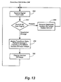
- the act in box 264 accesses transform data 202 to obtain data indicating a transform operation for the indicated change of parameter; processor 186 performs the transform using the input image data item from box 230 to obtain another data item defining another output image that is a version of the input image, as in box 232.
- the version obtained in box 264 when presented by display 192, shows the input image as it would appear when presented by the current type of devices operating with the changed parameter.
- Transform data for use in box 264 could be obtained similarly to the technique described above in relation to Figs. 9 and 10, with the following modifications:
- the act in box 150 could receive a request that also indicates a parameter value.
- the act in box 152 could perform the same operation the indicated type would perform so that the training image is presented by the indicated device with the indicated parameter value.
- internal parameters could include other operating parameters of an image output device, such as single or multiple pass printing or paper tray selection for a printer, and so forth.
- the act in box 152 could also perform a similar sequence of one or more basic image processing operations on the version presented on the display to provide a first approximation, storing the sequence on the transform stack as a starting point for the act in box 162.
- the user may move to an appropriate position or move the indicated device to an appropriate position to simulate the indicated parameter value.
- an angle of observation for example, basic image processing operations such as keystoning and change of contrast should obtain a displayed version showing the image as it would appear when viewed from the indicated angle of observation.
- the parameter value is a viewing distance or a projection distance for an image output device that is a projector, basic image processing operations such as subsampling or pixel replication should obtain a displayed version showing the image as it would appear when viewed from the indicated viewing distance or when projected at the indicated projection distance.
- Other possible external parameters include color or other attribute of paper of other marking medium for a printer and ambient light level for a display.
- the user can provide a save signal as in box 160.
- the act in box 170 rather than simply storing transform data so that it can be accessed by type of devices as in box 242 in Fig. 12, would also store it so that it can be accessed by parameter value in box 264 in Fig. 13.
- processor 186 provides an output image data item from box 264 to display 192.
- Display 192 responds by presenting the output image as described in relation to box 244 above.
- Figs. 14 and 15 can be used to implement the act in box 250 in Fig. 12 and the act in box 268 in Fig. 13.
- processor 186 can access transform data 202 and perform any transforms necessary to obtain a presentation version of the input image from box 230 appropriate for presentation on the currently indicated type of image output devices with current parameter values for that type of devices.
- the act in box 280 may, for example, transform the input image into a form appropriate for a page description language (PDL) data structure.
- PDL data structure may also include the current parameter values, or the parameter values may be provided in another appropriate form.
- the act in box 282 provides the presentation version of the input image to the device of the currently indicated type for presentation.
- processor 186 can access transform data 202 and perform a transform that uses data defining the currently displayed image to obtain a presentation version for presentation on the currently indicated type of image output devices with the current parameter values. Similar to the act in box 280, the act in box 290 may transform the displayed image into a form appropriate for a PDL data structure. If the data defining the currently displayed image indicates pixel values, for example, the pixel values can be included in the PDL data structure in an appropriate form.
- the act in box 292 provides the presentation version of the input image to the device of the currently indicated type for presentation, as in box 282.
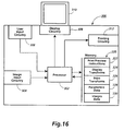
- Figs. 16 and 17 illustrate a print previewing implementation of the features described above in relation to Figs. 3 and 4 that extends the technique described above in relation to Fig. 15.
- processor 302 is connected for receiving data defining input images from input image circuitry 304.
- Processor 302 is also connected for receiving signals from a user through user input circuitry 306.
- Processor 302 is connected for providing data defining output images to display circuitry 308, which presents images on display 310, and to printing circuitry 312, which prints images on marking media such as paper.
- Display 310 has sufficient resolution to present output images as they would appear when printed by printing circuitry 312.
- Processor 302 is connected for accessing memory 320, which can include program and data memories.
- Print preview instructions 322 can be stored in program memory, and processor 302 can execute instructions 322 in performing the acts described below in relation to Fig. 17.
- Display transforms 324 could be stored either in program memory or in data memory, depending on how transform operations are implemented, and could in either case be accessed by processor 302 when preparing data defining an output image for presentation on display 310.
- print transforms 326 could be stored either in program memory or in data memory and could in either case be accessed by processor 302 when preparing data defining an output image for printing by printing circuitry 312.
- Parameters data 328 can be stored in data memory, and indicate current parameters for printing circuitry 312.
- Images data 330 define images.
- the act in box 350 in Fig. 17 begins by initializing parameter data 328 to indicate default values of the parameters for printing circuitry 312.
- the act in box 352 then receives a signal from user input circuitry 306.
- the act in box 360 branches on the signal.
- the act in box 362 receives data defining an input image from image input circuitry 304.
- the data defining the input image can be stored in images data 330.
- the act in box 364 accesses display transforms 324 to obtain a default transform, which is performed on the input image to obtain data defining a default version, similarly to box 232 in Fig. 12.
- the data defining the default version can be stored in images data 330.
- the act in box 366 provides the default version to display circuitry 308, which presents the default version on display 310.
- the act in box 370 stores the indicated value in parameters data 328.
- the act in box 370 also uses the value to access display transform 324 to obtain a transform for the value, which is performed on data from images data 330 that define the currently displayed image.
- the transform obtains data defining a transformed version of the currently displayed image as it would appear when printed by printing circuitry 312 with the indicated parameter value.
- the data defining the transformed version could also be stored in images data 330.
- box 372 provides the data defining the transformed version to display circuitry 308, which presents the transformed version on display 310.
- the act in box 374 accesses print transform 326 and performs the print transform on data defining the currently displayed image to obtain data defining a print version.
- the act in box 376 then provides the print version to printing circuitry 376, which prints an image that appears substantially identical to the displayed image.
- the implementations described above receive user signals indicating a type of image output devices, changes in parameters, and requests to present an image.
- the invention could be implemented to receive user signals of other types, including signals requesting editing operations on a presented image.
- the implementation described above receives user signals that are provided by selecting menu items or buttons or by providing keystrokes.
- the invention could be implemented to receive user signals that are provided in other ways, such as by using user input circuitry other than a keyboard and a mouse.
- the implementation described above obtains transform data by allowing a user to compare a training image as presented by a particular type of image output devices to the same training image as presented by a high resolution display after each of a sequence of basic image processing operations.
- the invention could also be implemented by analyzing the structure of a type of image output devices to obtain transform data indicating an appropriate transform.
- the invention could be applied in many ways, including previewing for copiers and peripheral printers.
- machine 180 in Fig. 11 could include image input circuitry 182, user input circuitry 184, processor 186, memory 190, and display 192 as shown.
- machine 180 could include scanner 212 and two or more image output devices 194 through 196, each of which is a printer or circuitry for connecting to a printer.
- the invention could be applied, for example, with a copier.
- machine 180 in Fig. 11 could include image input circuitry 182, user input circuitry 184, processor 186, memory 190, and display 192 as shown, all of which would be included in a workstation, personal computer, or other data processing system.
- machine 180 could include image output circuitry for connecting to two or more image output devices 194 through 196, each of which is a peripheral printer of a different type. The invention could be applied, for example, with a printer.
- the invention has been described in relation to software implementations, but the invention might be implemented with specialized hardware.
- the invention has been described in relation to implementations in which a processor executes instructions to perform transform operations.
- the invention might also be implemented with a specialized processor that performs such operations without executing instructions.
Landscapes
- Engineering & Computer Science (AREA)
- Multimedia (AREA)
- Signal Processing (AREA)
- Facsimiles In General (AREA)
- Controls And Circuits For Display Device (AREA)
- Processing Or Creating Images (AREA)
Applications Claiming Priority (2)
| Application Number | Priority Date | Filing Date | Title |
|---|---|---|---|
| US23501794A | 1994-04-28 | 1994-04-28 | |
| US235017 | 1994-04-28 |
Publications (2)
| Publication Number | Publication Date |
|---|---|
| EP0680200A2 true EP0680200A2 (de) | 1995-11-02 |
| EP0680200A3 EP0680200A3 (de) | 1996-06-05 |
Family
ID=22883724
Family Applications (1)
| Application Number | Title | Priority Date | Filing Date |
|---|---|---|---|
| EP95302790A Ceased EP0680200A3 (de) | 1994-04-28 | 1995-04-26 | Bildanzeigeverfahren. |
Country Status (3)
| Country | Link |
|---|---|
| US (1) | US6078936A (de) |
| EP (1) | EP0680200A3 (de) |
| JP (1) | JPH0818703A (de) |
Cited By (1)
| Publication number | Priority date | Publication date | Assignee | Title |
|---|---|---|---|---|
| WO2008021660A1 (en) * | 2006-08-15 | 2008-02-21 | 3M Innovative Properties Company | Display simulator |
Families Citing this family (45)
| Publication number | Priority date | Publication date | Assignee | Title |
|---|---|---|---|---|
| JPH11112819A (ja) * | 1997-09-30 | 1999-04-23 | Fuji Photo Film Co Ltd | 色変換ルックアップテーブル並びにその作成方法および装置並びにそれを用いた画像の色変換方法および装置 |
| US7263659B2 (en) * | 1998-09-09 | 2007-08-28 | Ricoh Company, Ltd. | Paper-based interface for multimedia information |
| US6731309B1 (en) | 1998-08-28 | 2004-05-04 | Corel Corporation | Real time preview |
| US6970894B2 (en) * | 1998-12-30 | 2005-11-29 | Intel Corporation | Method for extracting information from a file using a printer driver |
| US6529214B1 (en) * | 1999-05-14 | 2003-03-04 | Checkerboard Ltd. | Interactive print job display system and method |
| US6976223B1 (en) * | 1999-10-04 | 2005-12-13 | Xerox Corporation | Method and system to establish dedicated interfaces for the manipulation of segmented images |
| US7117170B1 (en) | 1999-10-06 | 2006-10-03 | Stamps.Com Inc. | Apparatus, systems and methods for applying billing options for multiple carriers for online, multi-carrier, multi-service parcel shipping management |
| US7664651B1 (en) | 1999-10-06 | 2010-02-16 | Stamps.Com Inc. | Apparatus, systems and methods for online, multi-carrier, multi-service parcel shipping management |
| US7197465B1 (en) * | 1999-10-06 | 2007-03-27 | Stamps.Com Inc. | Apparatus, systems and methods for printing dimensionally accurate symbologies on laser printers configured with remote client computer devices |
| US7359887B1 (en) | 1999-10-06 | 2008-04-15 | Stamps.Com Inc. | Apparatus, systems and methods for interfacing with digital scales configured with remote client computer devices |
| JP3634695B2 (ja) * | 1999-11-02 | 2005-03-30 | キヤノン株式会社 | 印刷制御方法および装置 |
| US7065716B1 (en) * | 2000-01-19 | 2006-06-20 | Xerox Corporation | Systems, methods and graphical user interfaces for previewing image capture device output results |
| US6993575B2 (en) * | 2000-02-22 | 2006-01-31 | Oracle International Corporation | Using one device to configure and emulate web site content to be displayed on another device |
| EP1176500A1 (de) * | 2000-07-28 | 2002-01-30 | Hewlett-Packard Company, A Delaware Corporation | Verfahren und Gerät für Druckvorschau in einem Drucker |
| EP1362283B1 (de) * | 2000-11-21 | 2005-01-26 | Jürgen Kohn | Verfahren und vorrichtung zum darstellen eines aus pixeln aufgebauten bildes |
| GB0107766D0 (en) * | 2001-03-28 | 2001-05-16 | Hewlett Packard Co | Improvements relating to developing documents |
| GB0107784D0 (en) * | 2001-03-28 | 2001-05-16 | Hewlett Packard Co | Improvement relating to developing documents |
| US7333071B2 (en) * | 2001-05-11 | 2008-02-19 | Xerox Corporation | Methods of using mixed resolution displays |
| US20020171685A1 (en) * | 2001-05-16 | 2002-11-21 | Christianson Eric P. | Using icons to represent physical keys in navigation aids |
| US20020171684A1 (en) * | 2001-05-16 | 2002-11-21 | Christianson Eric P. | Using icon-based input cues |
| US20030002056A1 (en) * | 2001-05-22 | 2003-01-02 | Matsushita Electric Industrial Co., Ltd. | Printing apparatus and pre-printing information estimating method |
| JP2002373215A (ja) * | 2001-06-15 | 2002-12-26 | Konica Corp | 製本システムおよび製本出力方法 |
| US7239412B2 (en) * | 2002-01-31 | 2007-07-03 | Sharp Laboratories Of America, Inc. | True print preview method and apparatus |
| US20040010756A1 (en) * | 2002-07-09 | 2004-01-15 | Hobbs George Bradley | Print preview based on printer attributes and/or material properties of print media |
| US7233404B2 (en) * | 2002-10-29 | 2007-06-19 | International Business Machines Corporation | System for processing print jobs |
| US20040111435A1 (en) * | 2002-12-06 | 2004-06-10 | Franz Herbert | System for selecting and creating composition formulations |
| JP2004268462A (ja) * | 2003-03-10 | 2004-09-30 | Konica Minolta Holdings Inc | 画像形成システム、画像形成装置及び画像形成方法 |
| EP1629359A4 (de) | 2003-04-07 | 2008-01-09 | Sevenecho Llc | Verfahren, system und software für erzählerische personalisierung digitaler medien |
| EP1642438A1 (de) * | 2003-06-27 | 2006-04-05 | Koninklijke KPN N.V. | Verfahren zur verwaltung von inhalt |
| US7310693B2 (en) * | 2003-08-01 | 2007-12-18 | Océ-Technologies B.V. | Method and apparatus for viewing on a client computer's display device a preview of a print document to be printed |
| US7075552B2 (en) * | 2003-08-25 | 2006-07-11 | Integrated Color Solutions, Inc. | System and method for display grid characterization, calibration, and verification |
| US6937249B2 (en) | 2003-11-07 | 2005-08-30 | Integrated Color Solutions, Inc. | System and method for display device characterization, calibration, and verification |
| US7580062B2 (en) * | 2003-12-04 | 2009-08-25 | Canon Kabushiki Kaisha | Image capturing system, image capturing method, and recording medium, program, and display method used therewith |
| US7779355B1 (en) | 2004-03-30 | 2010-08-17 | Ricoh Company, Ltd. | Techniques for using paper documents as media templates |
| US20060082816A1 (en) * | 2004-10-15 | 2006-04-20 | Lexmark International, Inc. | Printer device and related method for handling print-and-hold jobs |
| JP5157898B2 (ja) * | 2006-03-30 | 2013-03-06 | 日本電気株式会社 | 画像処理装置、画像処理システム、画像処理方法および画像処理用プログラム |
| US8819556B1 (en) | 2007-02-02 | 2014-08-26 | Adobe Systems Incorporated | Methods and systems for displaying format properties of crop areas |
| US7831901B1 (en) | 2007-02-16 | 2010-11-09 | Adobe Systems Incorporated | Systems and methods employing multiple crop areas |
| JP4897509B2 (ja) * | 2007-02-21 | 2012-03-14 | 株式会社リコー | 画像処理装置、プレビュー画像表示方法およびプレビュー画像表示プログラム |
| US8005316B1 (en) * | 2007-05-16 | 2011-08-23 | Adobe Systems Incorporated | System and method for editing image data for media repurposing |
| JP5412038B2 (ja) * | 2008-01-29 | 2014-02-12 | 京セラドキュメントソリューションズ株式会社 | 画像形成装置および画像情報保存方法 |
| US8934119B2 (en) * | 2009-08-04 | 2015-01-13 | Electronics For Imaging, Inc. | Greenbooks |
| US8885181B2 (en) * | 2009-08-04 | 2014-11-11 | Electronics For Imaging, Inc. | Virtual press run |
| US8610938B2 (en) * | 2011-08-08 | 2013-12-17 | Canon Kabushiki Kaisha | Remote print preview generation |
| EP3521997A1 (de) * | 2018-02-05 | 2019-08-07 | OCE Holding B.V. | Verfahren zum erstellen einer realistischen vorschau von bögen eines druckauftrags |
Family Cites Families (48)
| Publication number | Priority date | Publication date | Assignee | Title |
|---|---|---|---|---|
| US4588282A (en) * | 1976-08-27 | 1986-05-13 | Levine Alfred B | Multiplexed photocopier system with portable scanner |
| US4174175A (en) * | 1977-04-22 | 1979-11-13 | Dimaria James D | Copy preview apparatus |
| US4495490A (en) * | 1981-05-29 | 1985-01-22 | Ibm Corporation | Word processor and display |
| US4491933A (en) * | 1982-03-18 | 1985-01-01 | Wordtronix Inc. | Word processor |
| US4714940A (en) * | 1983-08-16 | 1987-12-22 | Canon Kabushiki Kaisha | Image processing apparatus having display means to monitor and display information from a date input section |
| US4613945A (en) * | 1984-05-07 | 1986-09-23 | Pitney Bowes Inc. | Method and apparatus for creating fonts for an electronic character generator |
| JPS6195665A (ja) * | 1984-10-17 | 1986-05-14 | Fuji Xerox Co Ltd | 画像読取り装置 |
| JPS6181258U (de) * | 1984-10-30 | 1986-05-29 | ||
| US4677571A (en) * | 1985-02-08 | 1987-06-30 | Rise Technology Inc. | Electronic publishing |
| US4800510A (en) * | 1985-07-31 | 1989-01-24 | Computer Associates International, Inc. | Method and system for programmed control of computer generated graphics layout |
| US4656524A (en) * | 1985-12-23 | 1987-04-07 | Polaroid Corporation | Electronic imaging copier |
| DE3629462C2 (de) * | 1986-08-29 | 1996-05-15 | Agfa Gevaert Ag | Verfahren und Vorrichtung zur elektronischen Bildverarbeitung mit Zwischenspeicherung |
| US4839829A (en) * | 1986-11-05 | 1989-06-13 | Freedman Henry B | Automated printing control system |
| US4740814A (en) * | 1987-01-09 | 1988-04-26 | Xerox Corporation | Preview system for an electrophotographic printing machine |
| US4951233A (en) * | 1987-08-05 | 1990-08-21 | Hitachi, Ltd. | Document producing apparatus having in-document layout display |
| US5163122A (en) * | 1987-12-09 | 1992-11-10 | Fuji Photo Film Co., Ltd. | Image processing system |
| US4979032A (en) * | 1988-12-27 | 1990-12-18 | Eastman Kodak Company | Color imaging apparatus producing on various image receptive materials a visually matched hard copy reproduction of a video image displayed |
| US4958220A (en) * | 1988-12-27 | 1990-09-18 | Eastman Kodak Company | Color imaging apparatus producing visually matched displays of perceptually distinct reproduced images |
| US5210824A (en) * | 1989-03-03 | 1993-05-11 | Xerox Corporation | Encoding-format-desensitized methods and means for interchanging electronic document as appearances |
| US5029107A (en) * | 1989-03-31 | 1991-07-02 | International Business Corporation | Apparatus and accompanying method for converting a bit mapped monochromatic image to a grey scale image using table look up operations |
| US5420979A (en) * | 1989-12-22 | 1995-05-30 | Eastman Kodak Company | Method and apparatus for using composite transforms to form intermediary image data metrics which achieve device/media compatibility for subsequent imaging applications |
| US5164842A (en) * | 1990-06-29 | 1992-11-17 | Xerox Corporation | Job/page proofing for electronic printers |
| JPH0493894A (ja) * | 1990-08-03 | 1992-03-26 | Canon Inc | 文字処理方法および装置 |
| JPH04246690A (ja) * | 1990-08-29 | 1992-09-02 | Xerox Corp | 高品質のイメージを並みの解像度で表示する方法 |
| GB2278250B (en) * | 1990-08-31 | 1995-03-15 | Canon Kk | Image processing |
| US5208903A (en) * | 1990-09-10 | 1993-05-04 | Eastman Kodak Company | Video image display for predicting color hardcopy image quality |
| WO1992010791A1 (en) * | 1990-12-13 | 1992-06-25 | F & S Incorporated | Apparatus and method for producing color corrected reproductions of colored original images |
| US5239389A (en) * | 1991-06-27 | 1993-08-24 | Hewlett-Packard Company | Preview print for facsimile transmission |
| JP3084807B2 (ja) * | 1991-07-10 | 2000-09-04 | ブラザー工業株式会社 | 印字装置 |
| IL98902A (en) * | 1991-07-21 | 1995-07-31 | Scitex Corp Ltd | A system for proofreading a printed product |
| US5367673A (en) * | 1991-08-23 | 1994-11-22 | Eastman Kodak Company | System for queueing request from remote stations for proof processing of files that are transmitted only when processing resources become available |
| US5739928A (en) * | 1991-09-12 | 1998-04-14 | Eastman Kodak Company | Technique particularly suited for use in a print preview function for adapting CRT colorimetry to ambient lighting conditions |
| US5257097A (en) * | 1991-09-27 | 1993-10-26 | Eastman Kodak Company | Method and apparatus for selective interception of a graphics rendering operation for effecting image data modification |
| JPH0820937B2 (ja) * | 1991-10-18 | 1996-03-04 | インターナショナル・ビジネス・マシーンズ・コーポレイション | 異なるアプリケーションに対し選択したプリンタの応答を表示する方法及び装置 |
| US5416890A (en) * | 1991-12-11 | 1995-05-16 | Xerox Corporation | Graphical user interface for controlling color gamut clipping |
| US5309257A (en) * | 1991-12-31 | 1994-05-03 | Eastman Kodak Company | Method and apparatus for providing color matching between color output devices |
| JPH05346953A (ja) * | 1992-06-15 | 1993-12-27 | Matsushita Electric Ind Co Ltd | 画像データ処理装置 |
| US5384901A (en) * | 1992-10-22 | 1995-01-24 | Xerox Corporation | Method of rendering a color image for an output medium from symbolic image data |
| US5301037A (en) * | 1992-11-25 | 1994-04-05 | Xerox Corporation | Resolution conversion with simulated multi-bit gray |
| US5604843A (en) * | 1992-12-23 | 1997-02-18 | Microsoft Corporation | Method and system for interfacing with a computer output device |
| US5519501A (en) * | 1993-06-21 | 1996-05-21 | Xerox Corporation | Proofing images in a print job having at least one image in a print job having at least one image for printing on tab stock |
| US5731823A (en) * | 1994-01-27 | 1998-03-24 | Hewlett-Packard Company | Automatic optimization of hardcopy output for enhanced appearance and throughput |
| US5745156A (en) * | 1994-04-28 | 1998-04-28 | Xerox Corporation | Digital printer using two-dimensional, full frame light valve |
| US5703621A (en) * | 1994-04-28 | 1997-12-30 | Xerox Corporation | Universal display that presents all image types with high image fidelity |
| US5491347A (en) * | 1994-04-28 | 1996-02-13 | Xerox Corporation | Thin-film structure with dense array of binary control units for presenting images |
| US5627662A (en) * | 1994-04-28 | 1997-05-06 | Xerox Corporation | Digital imaging system using two-dimensional input sensor array and output light valve |
| US5436730A (en) * | 1994-07-05 | 1995-07-25 | Xerox Corporation | Method of managing a proof approval process for proofing documents in a printing system |
| US5598520A (en) * | 1994-09-26 | 1997-01-28 | Microsoft Corporation | Methods and apparatus for hinting a font for controlling stem width as font size and resolution of output device vary |
-
1995
- 1995-04-21 JP JP7097099A patent/JPH0818703A/ja active Pending
- 1995-04-26 EP EP95302790A patent/EP0680200A3/de not_active Ceased
-
1996
- 1996-07-12 US US08/679,169 patent/US6078936A/en not_active Expired - Lifetime
Cited By (2)
| Publication number | Priority date | Publication date | Assignee | Title |
|---|---|---|---|---|
| WO2008021660A1 (en) * | 2006-08-15 | 2008-02-21 | 3M Innovative Properties Company | Display simulator |
| US7593017B2 (en) | 2006-08-15 | 2009-09-22 | 3M Innovative Properties Company | Display simulator |
Also Published As
| Publication number | Publication date |
|---|---|
| JPH0818703A (ja) | 1996-01-19 |
| US6078936A (en) | 2000-06-20 |
| EP0680200A3 (de) | 1996-06-05 |
Similar Documents
| Publication | Publication Date | Title |
|---|---|---|
| EP0680200A2 (de) | Bildanzeigeverfahren | |
| JP3101363B2 (ja) | 等価性インジケータを備えたユーザによる規定が可能なフォント置換装置 | |
| US5119079A (en) | Touch screen user interface with expanding touch locations for a reprographic machine | |
| US6222538B1 (en) | Directing image capture sequences in a digital imaging device using scripts | |
| EP0664023B1 (de) | Betriebssystem mit objektorientierter druckschnittstelle | |
| US4649513A (en) | Apparatus and method for processing system printing data records on a page printer | |
| US6486914B1 (en) | Method and system for controlling user interaction in a digital imaging device using dynamic overlay bars | |
| US20070297010A1 (en) | Printing apparatus, printing method, image processing apparatus, image processing method, storage medium, and program | |
| CA1289277C (en) | Image data display system | |
| JP3725368B2 (ja) | 画像の表示択方法、コンピュータ・システムおよび記録媒体 | |
| US20080074694A1 (en) | Image processing apparatus | |
| US7382919B2 (en) | System and method for editing image data | |
| JPH08207380A (ja) | オリジナルフォームに自動的に記入する方法及び装置 | |
| JPH11224173A (ja) | 出力ジョブ発生方法 | |
| US8253967B2 (en) | Information processing apparatus and information processing method | |
| US20080218814A1 (en) | Color Proofing Method | |
| US20060075362A1 (en) | Image processing apparatus, method, and recording medium on which program is recorded for displaying thumbnail/preview image | |
| JPH06111083A (ja) | ビデオidフォトシステム | |
| JP2003200637A (ja) | プリンタおよびプリンタの印刷レイアウト設定方法 | |
| US7170638B2 (en) | Method, system and recording medium for image processing | |
| JPH0795403A (ja) | 画質情報に基づいて校正刷りイメージを印刷する装置 | |
| US8856208B2 (en) | Method and apparatus for forming image | |
| US7986423B2 (en) | Image reprinting apparatus and method | |
| EP0911729A1 (de) | Twainarchitektur | |
| JP2001148068A (ja) | 画像印刷販売機およびそのプログラム記録媒体 |
Legal Events
| Date | Code | Title | Description |
|---|---|---|---|
| PUAI | Public reference made under article 153(3) epc to a published international application that has entered the european phase |
Free format text: ORIGINAL CODE: 0009012 |
|
| AK | Designated contracting states |
Kind code of ref document: A2 Designated state(s): DE FR GB |
|
| PUAL | Search report despatched |
Free format text: ORIGINAL CODE: 0009013 |
|
| AK | Designated contracting states |
Kind code of ref document: A3 Designated state(s): DE FR GB |
|
| 17P | Request for examination filed |
Effective date: 19961205 |
|
| 17Q | First examination report despatched |
Effective date: 19980821 |
|
| APAB | Appeal dossier modified |
Free format text: ORIGINAL CODE: EPIDOS NOAPE |
|
| APAB | Appeal dossier modified |
Free format text: ORIGINAL CODE: EPIDOS NOAPE |
|
| APAD | Appeal reference recorded |
Free format text: ORIGINAL CODE: EPIDOS REFNE |
|
| STAA | Information on the status of an ep patent application or granted ep patent |
Free format text: STATUS: THE APPLICATION HAS BEEN REFUSED |
|
| 18R | Application refused |
Effective date: 20020911 |
|
| APAF | Appeal reference modified |
Free format text: ORIGINAL CODE: EPIDOSCREFNE |