EP0680209B1 - Fernsehbildkodier- und Aufnahmevorrichtung und Fernsehbildkodier-, Aufnahme- und Wiedergabevorrichtung - Google Patents
Fernsehbildkodier- und Aufnahmevorrichtung und Fernsehbildkodier-, Aufnahme- und Wiedergabevorrichtung Download PDFInfo
- Publication number
- EP0680209B1 EP0680209B1 EP19950302710 EP95302710A EP0680209B1 EP 0680209 B1 EP0680209 B1 EP 0680209B1 EP 19950302710 EP19950302710 EP 19950302710 EP 95302710 A EP95302710 A EP 95302710A EP 0680209 B1 EP0680209 B1 EP 0680209B1
- Authority
- EP
- European Patent Office
- Prior art keywords
- coefficient data
- blocks
- coding
- recording
- data
- Prior art date
- Legal status (The legal status is an assumption and is not a legal conclusion. Google has not performed a legal analysis and makes no representation as to the accuracy of the status listed.)
- Expired - Lifetime
Links
Images


Classifications
-
- H—ELECTRICITY
- H04—ELECTRIC COMMUNICATION TECHNIQUE
- H04N—PICTORIAL COMMUNICATION, e.g. TELEVISION
- H04N5/00—Details of television systems
- H04N5/76—Television signal recording
- H04N5/91—Television signal processing therefor
- H04N5/92—Transformation of the television signal for recording, e.g. modulation, frequency changing; Inverse transformation for playback
- H04N5/926—Transformation of the television signal for recording, e.g. modulation, frequency changing; Inverse transformation for playback by pulse code modulation
- H04N5/9261—Transformation of the television signal for recording, e.g. modulation, frequency changing; Inverse transformation for playback by pulse code modulation involving data reduction
- H04N5/9264—Transformation of the television signal for recording, e.g. modulation, frequency changing; Inverse transformation for playback by pulse code modulation involving data reduction using transform coding
-
- H—ELECTRICITY
- H04—ELECTRIC COMMUNICATION TECHNIQUE
- H04N—PICTORIAL COMMUNICATION, e.g. TELEVISION
- H04N19/00—Methods or arrangements for coding, decoding, compressing or decompressing digital video signals
- H04N19/85—Methods or arrangements for coding, decoding, compressing or decompressing digital video signals using pre-processing or post-processing specially adapted for video compression
- H04N19/88—Methods or arrangements for coding, decoding, compressing or decompressing digital video signals using pre-processing or post-processing specially adapted for video compression involving rearrangement of data among different coding units, e.g. shuffling, interleaving, scrambling or permutation of pixel data or permutation of transform coefficient data among different blocks
-
- H—ELECTRICITY
- H04—ELECTRIC COMMUNICATION TECHNIQUE
- H04N—PICTORIAL COMMUNICATION, e.g. TELEVISION
- H04N5/00—Details of television systems
- H04N5/76—Television signal recording
- H04N5/78—Television signal recording using magnetic recording
- H04N5/782—Television signal recording using magnetic recording on tape
- H04N5/7824—Television signal recording using magnetic recording on tape with rotating magnetic heads
- H04N5/7826—Television signal recording using magnetic recording on tape with rotating magnetic heads involving helical scanning of the magnetic tape
- H04N5/78263—Television signal recording using magnetic recording on tape with rotating magnetic heads involving helical scanning of the magnetic tape for recording on tracks inclined relative to the direction of movement of the tape
Definitions
- the present invention relates to a video image coding and recording apparatus and a video image coding, recording and reproducing apparatus used for compression encoding a video signal to a coded bit stream, and also to a method of arranging the compression codes on a recording medium, and further to an error correction of reproduced signals.
- DCT discrete cosine transformation
- variable length codes when an error occurs in the data according to the recording and reproducing, it becomes impossible to decode variable length codes at and after an error occurring point. Further, even if a discontinued point of the variable length codes is detected and variable length decodes are refreshed by a refreshing code or the like, the variable length codes cannot be decoded for a section from the error occurring point to a refreshment.
- An object of the present invention is to provide a video image coding and recording apparatus in which, in recording and reproducing by compression coding the digital video signals, no lack occurs in several coding blocks on the video screen even if an error occurs, and to provide a video image coding, recording and reproducing apparatus in which error corrects the coefficient data lost by occurrence of the error on recording or reproducing.
- the present invention provides a video image coding and recording apparatus comprising:
- the present invention provides a video image coding, recording and reproducing apparatus comprising:
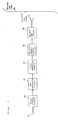
- Fig. 1 shows a block diagram of a video image coding and recording apparatus in a first embodiment of the present invention.
- Fig. 2 shows a conceptual diagram showing regions on a recording tape.
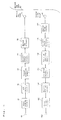
- Fig. 3 shows a block diagram of a video image coding, recording and reproducing apparatus in a second embodiment of the present invention.
- Fig. 4 shows a conceptual diagram showing coefficient data of coding blocks.
- Fig. 5 shows a block diagram of a video image coding, recording and reproducing apparatus in a fourth embodiment of the present invention.
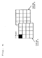
- Fig. 6 shows a conceptual diagram showing overlapping coded blocks
- Fig. 7 shows a block diagram of a video image coding, recording and reproducing apparatus in a fifth embodiment of the present invention.
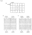
- Fig. 8 shows a first conceptual diagram showing divided groups of a coding block.
- Fig. 9 shows a second conceptual diagram showing divided groups of the coding block.
- Fig. 10 shows a third conceptual diagram showing divided groups of the coding blocks.
- Fig. 11 shows another conceptual diagram showing divided groups of the coding blocks.
- Fig.1 shows a block diagram of a video image coding and recording apparatus of the first embodiment.
- reference numeral 10 denotes an input terminal of a digital video signal
- reference numeral 20 denotes a block forming circuit
- reference numeral 30 denotes a DCT conversion circuit
- reference numeral 40 denotes a first shuffling memory
- reference numeral 50 denotes a variable length coding circuit
- reference numeral 60 denotes a recording circuit
- reference numeral 70 denotes a recording head
- reference numeral 80 denotes a recording tape.
- a digital video signal is supplied, and is divided into 4 ⁇ 4 coding blocks in the block forming circuit 20.
- An output of the block forming circuit 20 is frequency converted in each of the coding blocks by the DCT conversion circuit 30, and is stored as the coefficient data in the first shuffling memory 40.
- the variable length coding circuit 50 variable length codes the coefficient data outputted from the first shuffling memory 40 according to a predetermined shuffling rule.
- the predetermined shuffling rule is to allow at least that the coefficient data in a same coding block are present by mixture with the coefficient data in other coding blocks, and that the coefficient data in adjacent coding blocks on a video screen, or, the coefficient data in a coding block constituting a same region on the video screen and belonging to different fields may be recorded in distant regions on the recording tape 80 as in circle marks shown in Fig. 2 by shuffling the coefficient data.
- the coefficient data which has been variable length coding after shuffling as above are added to an error correcting code and subjected to channel coding in the recording circuit 60, and are supplied to the recording head 70 through a recording amplifier.
- the recording head 70 records the coefficient data on the recording tape 80.
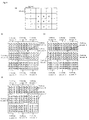
- FIG. 10 shows the four coding blocks A, B, C and D which are adjacent to one another in horizontal and vertical directions on the video screen.
- Fig. 10 shows the 16 coefficient data representing outputs of the DCT conversion circuit 30, or outputs of the four coding blocks A, B, C and D in alphabetical capital letters.
- Fig. 10 shows that the coefficient data from the four coding blocks A, B, C and D are present by mixture to constitute the new coding blocks W, X, Y and Z.
- the new coding blocks W, X, Y and Z are respectively variable length coded, and variable length codes respectively corresponding to the new coding blocks are recorded in the distant regions on the recording tape.
- the coefficient data which become impossible to be decoded by the error are present in a specific coding block, in adjacent regions on the video screen, or in the different fields, and are not concentrated on the same region on the video screen. Accordingly, it is possible to solve the significant problems such as lack of specific regions of an image on a reproduced screen, or the continuous periodical lack of images in the same region.
- variable length code in case of using a two dimension Huffman coding or the like which variable length codes by combining a number of the coefficient data of continual zeros with an amplitude of the coefficient data of succeeding non-zeros, it is effective to variable length code by reading out the coefficient data corresponding to a low band conversion degree in the coding block from the first shuffling memory 40 by shuffling as described above, and by continuously reading out the coefficient data corresponding to a high band conversion degree which has good possibility for the continual zeros in the coding block.
- FIG. 3 shows a block diagram of a video image coding, recording and reproducing apparatus according to the second embodiment.
- same reference numerals as used in the first embodiment are assigned and detailed explanation is omitted.
- reference numeral 42 denotes a second shuffling memory
- reference numeral 90 denotes a reproducing head
- reference numeral 100 denotes a reproducing circuit
- reference numeral 110 denotes a variable length decoding circuit
- reference numeral 120 denotes a first deshuffling memory
- reference numeral 130 denotes a first error correction circuit
- reference numeral 140 denotes an inverse DCT conversion circuit
- reference numeral 150 denotes a block decomposition circuit
- reference numeral 1650 denotes an output terminal of the digital video signal.
- a difference therebetween is a shuffling rule in the shuffling memory allowing that the coefficient data in a same conversion degree in the adjacent coding blocks on the video screen or the coefficient data in the same conversion degree of the coding block belonging to the different fields and constituting the same region on the video screen are to be recorded in the distant regions on the recording tape 80.
- FIG. 11 shows nine coding blocks A, B, C, D, E, F, G, H and I which are adjacent in the horizontal and vertical directions on the video screen.
- Fig. 11 shows the outputs of the DCT conversion circuit 30, or outputs of the nine coding blocks in 16 coefficient data shown in alphabetical capital letters.
- Fig. 11 shows that the coefficient data from the nine coding blocks are present by mixture to constitute the new coding blocks R, S, T, U, V, W, X, Y and Z.
- the new coding blocks R, S, T, U, V, W, X, Y and Z are respectively variable length coding, and the variable length codes respectively corresponding to the new coding blocks are recorded in the distant regions on the recording tape.
- the reproducing head 90 supplies a reproducing output from the recording tape 80 to the reproduction circuit 100.
- the reproduction circuit 100 demodulates and error corrects the reproducing output, and supplies reproduced variable length coded coefficient data and an error correcting error flag showing a result of the error correcting the reproducing output to the variable length decoding circuit 110.
- the variable length decoding circuit 110 variable length decodes the reproduced variable length coded coefficient data, and outputs, along with the coefficient data, a decoding error flag showing whether the reproduced variable length coded coefficient data are variable length decoded correctly or not, to the first deshuffling memory 120.
- a generation of the decoding error flag is carried out by such steps as to output the decoding error flag to the coefficient data to be decoded in a section from an error generation point shown by the error correction error flag to refreshing a variable length decode by a refreshing code or the like, or to output the decoding error flag in a case that a predetermined number of the coefficient data is not carried out in the section in which the predetermined number of the coefficient data should be decoded.
- the first error correction circuit 130 reads out the coefficient data in the coding blocks which constitute the same region on the video screen and the decoding error flag corresponding to each of the reproduced variable length coded coefficient data from the first deshuffling memory 120, and corrects the reproduced variable length coded coefficient data on which an error has been detected.
- the correction of the reproduced variable length coded coefficient data is explained below.
- the coefficient data in the same conversion degree in the adjacent coding blocks on the video screen or the coefficient data in the same conversion degree of the coding block belonging to the different fields and constituting the same region on the video screen are recorded in the distant regions on the recording tape 80. Accordingly, the coefficient data which are in the same conversion degree as error detected coefficient data in the coding block on the video screen adjacent to the coding block which includes the error-detected coefficient data are correctly reproduced, so that the error detected coefficient data can be corrected as an average value of error-free coefficient data on the same conversion degree.
- the coefficient data in the same conversion degree in the coding block constituting the same region on the video screen as the coding block including the coefficient data in which an error has been detected and belonging to the different field is also correctly reproduced. Therefore, the coefficient data in which the error has been detected can be replaced by the error-free coefficient data in the same conversion degree as described above and corrected.
- the time-based correlations in the same region on the video screen are high. Accordingly, by error correcting by replacing the coefficient data in which the error has been detected by the error-free coefficient data of one field preceding order, visually obstacle-free reproduced images can be obtained.
- error correction can be carried out adaptively in the adjacent coding blocks or between the fields.
- the coefficient data in which the error corrections as explained above have been made are converted to the pixel data by the inverse DCT conversion circuit 140 and supplied to the block decomposing circuit 150.
- the block decomposing circuit 150 converts the pixel data divided into the coding blocks to the digital video signals, and outputs- to the output terminal 160.
- the coefficient data in the same conversion degree in the adjacent coding blocks on the video screen or the coefficient data in the same conversion degree in the coding block constituting the same region on the video screen and belonging to the different fields are recorded in the distant regions on recording medium, and when reproducing, the average value of the plural coefficient data in the same conversion degree as the error detected coefficient data in the coding block on the video screen adjacent to the coding block including the error-detected coefficient data or the coefficient data in the same conversion degree in the coding block constituting the same region on the video screen as the coding block including the coefficient data in which an error has been detected and belonging to the different field replace the coefficient data which the error is detected and correct the error.
- the constitution of the video image coding, recording and reproducing apparatus of the third embodiment is the same as the constitution of the video image coding, recording and reproducing apparatus of the second embodiment shown in Fig. 3. But an error correcting method is different. A following description refers to the error correcting method only.
- the error correcting method of the third embodiment is to correct an error by using pixel correlation at a boundary of the adjacent coding blocks on the video screen. Hereinafter, description is made on the error correcting method using the pixel correlation.
- the correlation between the adjacent pixels on the video screen is large, and the pixel correlation at the boundary between the adjacent coding blocks is also large.
- the coefficient data in the coding block has been lost by error
- the lost coefficient data is taken as zero and the coding block is decoded to the pixel data
- the pixels at the boundary between the adjacent coding blocks have smaller correlations.
- Such a change in the pixel correlations is caused by the fact that the coefficient data to be originally reproduced has become impossible to be reproduced by the error, and the coefficient data has been replaced by zeros.
- aij, bij, Aij, and Bij are respectively elements of a matrix of 4 X 4.
- D is a matrix representing the conversion basis of the DCT conversion of 4 X 4, as shown below:
- the boundary pixels of the coding block A and the coding block B are respectively expressed as: As the pixel correlation between the boundary pixels of the coding block A and the coding block B are large, it is considered that (5) and (6) are equal, so that the following equation between the coefficient data is obtained: As the coefficient data A11 is not correctly reproduced because of the error and other coefficient data are correctly reproduced, the equation (7) is solved with a column vector which includes the coefficient data A11, which gives the following equation:
- the equation (8) indicates that it is possible to obtain the coefficient data containing the error by utilizing the pixel correlation between the boundary pixels by making the coefficient data containing the error zero.
- the expression (1) to be used for the error correction is derived from the equation (8) with respect to the coefficient data A11 in which the error occurred.
- the error correction has been made to the coefficient data A11 in which the error has occurred by using the pixel correlation between the boundary pixels with the coding block adjacent to the right side in the horizontal direction, but the error correction by the similar operation made on a left side in the horizontal direction or between the upper and lower coding blocks is also possible.
- Fig. 5 shows a block diagram of the video image coding, recording and reproducing apparatus of the fourth embodiment.
- the same elements as those of the second embodiment are indicated with the same reference numerals as used in the second embodiment and detailed explanation is omitted.
- reference numeral 25 denotes an overlap block forming circuit
- reference numeral 132 denotes a second error correcting circuit
- reference numeral 155 denotes an overlap block decomposing circuit.
- the overlap block circuit 25 divides the digital video signal into the coding blocks by overlapping so that the adjacent two 4 X 4 coding blocks mutually co-possess the one pixel at the boundary on the video screen, as shown in Fig. 6, and supplies the coding block to the DCT conversion circuit 30.
- the DCT converted coefficient data are subjected to the coefficient shuffling, variable length coding, and recording in the same manner as in the second embodiment and recorded on the recording tape 80.
- variable length decoding circuit 110 variable length decodes the reproduced variable length coded coefficient data and outputs the decoding error flag showing whether the reproduced variable length coded coefficient data are decoded correctly or not, along with the coefficient data, to the first deshuffling memory 120.
- the second error correction circuit 132 reads out from the above first deshuffling memory 120 the coefficient data corresponding to the two coded blocks overlapped on the video screen and the decoding error flag corresponding to the coefficient data, carries out error correction, and supplies the error-corrected coefficient data to the inverse DCT conversion circuit 140.
- the error correction between the overlapped coding blocks in the fourth embodiment is performed under the same operation as in the third embodiment.
- the inverse DCT conversion circuit 140 converts the error corrected coefficient data to the pixel data and supplies the pixel data to the overlap block decomposing circuit 155, and the overlap block decomposing circuit 155 converts the pixel data divided into the coding blocks to the digital video signals, and outputs to the output terminal 160.
- the fourth embodiment by dividing the digital video signals into the coding blocks so that the adjacent coding blocks mutually co-possess the one pixel at the boundary on the video screen, it becomes possible to carry out error correction similar to the error correction method as explained in the third embodiment by using the boundary pixel between the adjacent coding blocks which are originally identical pixels, thereby making it possible to realize more correct error correction and to enhance rapidly the stability of the video image coding, recording and reproducing apparatus.
- FIG. 7 shows a block diagram of the video image coding, recording and reproducing apparatus of the fifth embodiment.
- the same elements as those of the second embodiment and the third embodiment are indicated with the same reference numerals as used in the second embodiment and the third embodiment, and detailed explanation is omitted.
- reference numeral 43 denotes a third shuffling memory
- reference numeral 122 denotes a second deshuffling memory
- reference numeral 133 denotes a third error correcting circuit
- the digital video signal inputted from the input terminal 10 is divided in the overlap block forming circuit 25 into the coding blocks by overlapping so that the adjacent two 4 X 4 coding blocks mutually co-possess the one pixel at the boundary on the video screen, as shown in Fig. 6, and the coding blocks are supplied to the DCT conversion circuit 30.
- the DCT conversion circuit 30 frequency converts each of coding blocks to obtain the coefficient data, and the third shuffling memory 43 stores the coefficient data.
- the third shuffling memory 43 outputs the coefficient data according to a shuffling rule.
- the shuffling rule allows that the coefficient data are divided into three groups of a group 0 which includes four coefficient data which are in a lowest region of horizontal frequency components, a group 1 which includes the four coefficient data adjacent to the group 0, and a group 2 which includes 8 coefficient data not included in the group 0 or the group 1, as shown in Fig. 8. Further, the shuffling rule allows that at least six groups in the two overlapped coding blocks are recorded in the distant regions on the recording tape 80.
- the coefficient data are variable length coded in the variable length coding circuit 50, added to the error corrected code and subjected to channel coding in the recording circuit 60, and supplied to the recording head 70 through the recording amplifier.
- the recording head 70 records the coefficient data on the recording tape 80.
- the reproducing head 90 supplies the reproduction output from the recording tape 80 to the reproducing circuit 100.
- the reproducing circuit 100 demodulates and error corrects the reproducing output, supplies reproduced variable length coded coefficient data and the error correcting error flag showing the result of the error correcting the reproducing output to the variable length decoding circuit 110.
- the variable length decoding circuit 110 variable length decodes the reproduced variable length coded coefficient data and outputs the decoding error flag showing whether the reproduced variable length coded coefficient data are variable length decoded correctly or not, along with the coefficient data, to the second deshuffling memory 122.
- the third error correction circuit 133 reads out from the second deshuffling memory 122 the coefficient data in the coding blocks which constitute the same region on the video screen and the decoding error flag corresponding to each of the reproduced variable length coded coefficient data, and corrects the reproduced variable length coded -coefficient data on which the error has been detected.
- This correction method is basically the same as the correction method explained in the third embodiment.
- the error occurs in a unit of the group unit comprising a plurality of coefficient data.
- a group which is lost can be similarly obtained with respect to the coding block B.
- the error correction is made with the coefficient data included in the group 2 taken as zeros, because the energy of these coefficient data corresponding to these coefficient data is small and the visual sensitivity to these coefficient data is low, as described in the first embodiment.
- the six groups in the overlapped two coding blocks are recorded in the distant regions from one another on the recording tape 80, there is less possibility for plural groups to become errors simultaneously and be lost, so that the lost coefficient data can be nearly completely error corrected.
- the digital video signal is divided into the coding blocks so that the adjacent coding blocks on the video screen mutually co-possess the one pixel at the boundary, the coefficient data in the coding block are divided into groups, the coefficient data in each of groups having the same horizontal frequency components, the six groups included in the overlapped two coding blocks are recorded in the distant regions on the recording tape, and when correcting the error, correction is performed such that the pixels in the overlapped region become equal to each other between the overlapped two coding blocks. Accordingly, it becomes possible to correct the four lost coefficient data simultaneously, thereby making it possible to enhance the stability of the video image coding, recording and reproducing apparatus greatly.
- the two coefficient data in the low-band horizontal frequency components are group divided into the groups having the same horizontal frequency components.
- This group division is one example of a case that the plural coefficient data having no identical vertical frequency component are group divided into the groups.
- the group division as shown in Fig. 9 may be subjected to the error correction by the similar operation.
- the coefficient data in the coding blocks overlapping in the horizontal direction on the video screen are group divided into each coefficient data having no identical vertical frequency component to correct the error in the unit of the group.
- similar error correction is possible by such procedure that the coefficient data in the coding blocks overlapping in the vertical direction on the video screen are group divided into the group of the coefficient data having no horizontal frequency component.
- the coefficient data in the two rows corresponding to high band conversion degree are group divided into one group. This is because of the present intention to prevent lowering of the coding efficiency by variable length coding by using a two dimension Huffman code or the like in the variable length coding circuit and reading out the coefficient data to the high band conversion degree having high possibility of showing continual zeros in the coding block. If, in the variable length coding circuit, in a case of using a one dimension Huffman coding or the like or in a case of a relatively low compression ratio, group division is made by each row and error correction is made against a loss of all the coefficient data, then the reproduction image quality at the occurrence of the error can be made extremely high.
- the constitution has been explained on a premise of the recording head and the reproducing head being each single, but the number of each head is not limited to one, but same effect is obtained even in a case of two or more heads. Furthermore, when two or more heads are used, even if any head has been clogged to give failure to obtain a reproducing output, it is possible to carry out error correction effectively and obtain good reproduced video images.
Landscapes
- Engineering & Computer Science (AREA)
- Multimedia (AREA)
- Signal Processing (AREA)
- Television Signal Processing For Recording (AREA)
- Compression Or Coding Systems Of Tv Signals (AREA)
- Signal Processing For Digital Recording And Reproducing (AREA)
- Compression, Expansion, Code Conversion, And Decoders (AREA)
- Error Detection And Correction (AREA)
Claims (24)
- Videobild-Codier- und Aufzeichnungsvorrichtung, die aufweist:dadurch gekennzeichnet, daß die Umstellungseinrichtung eine Umordnungseinrichtung (40, 42, 43) zum Umordnen der Koeffizientendaten über zumindest zwei der Vielzahl der ersten Koeffizientendatenblöcke aufweist, so daß ein Teil der Koeffizientendaten in jedem der Vielzahl der ersten Koeffizientendatenblöcke durch Koeffizientendaten desselben Konversionsgrads, enthalten in einem anderen der Vielzahl der ersten Koeffizientendatenblöcke, ersetzt wird, um eine Vielzahl von zweiten Koeffizientendatenblöcken zu bilden, von denen jeder eine Vielzahl von Koeffizientendaten enthält, die von mindestens zwei der Vielzahl der ersten Koeffizientendatenblöcken abgeleitet sind, undeine Blockbildungseinrichtung (20, 25) zum Unterteilen eines digitalen Videosignals, um eine Vielzahl von Codierblöcken zu bilden, von denen jeder aus einer Vielzahl von Pixeldaten besteht;eine orthogonale Transformationseinrichtung (30) für eine orthogonale Transformation der Pixeldaten in jedem der Codierblöcke, um eine Vielzahl von ersten Koeffizientendatenblöcken zu erhalten, von denen jeder aus einer Vielzahl von Koeffizientendaten orthogonal transformiert von der Vielzahl der Pixeldaten besteht, die in einem entsprechenden einen der Vielzahl der Codierblöcke enthalten sind;eine Umstellungseinrichtung (40, 42, 43) zum Umstellen der Koeffizientendaten über zumindest zwei der Vielzahl der ersten Koeffizientendatenblöcke, um umgestellte Koeffizientendaten zu erhalten; undeine Aufzeichnungseinrichtung (50, 60, 70) zum Aufzeichnen der umgestellten Koeffizientendaten auf einem Aufzeichnungsmedium,
wobei die Aufzeichnungseinrichtung (50, 60, 70) die Vielzahl der zweiten Koeffizientendatenblöcke auf dem Aufzeichnungsmedium aufzeichnet, wodurch zumindest einige der Koeffizientendaten, die in jedem der Vielzahl der ersten Koeffizientendatenblöcke enthalten sind, zu unterschiedlichen Aufzeichnungsbereichen voneinander auf dem Aufzeichnungsmedium verteilt sind. - Vorrichtung nach Anspruch 1, wobei die Aufzeichnungseinrichtung (50, 60, 70) eine Einrichtung (50) zum Codieren der Koeffizientendaten der Vielzahl der zweiten Koeffizientendatenblöcke auf einer Basis zweiter Koeffizientendatenblock für zweiter Koeffizientendatenblock, um codierte Daten zu erhalten, wobei die Aufzeichungseinrichtung die codierten Daten auf dem Aufzeichnungsmedium aufzeichnet, umfaßt.
- Vorrichtung nach Anspruch 1 oder 2, wobei die Umordnungseinrichtung (40, 42, 43) die Koeffizientendaten so umordnet, daß Koeffizientendaten, die orthogonal von Pixeldaten transformiert sind, die in zwei Codierblöcken enthalten sind, die angrenzend zueinander auf einem Videoschirm sind, in Aufzeichnungsbereichen aufgezeichnet werden, die voneinander auf dem Aufzeichnungsmedium beabstandet sind.
- Vorrichtung nach Anspruch 1 oder 2, wobei die Umordnungseinrichtung (40; 42, 43) die Koeffizientendaten so umordnet, daß Koeffizientendaten, die orthogonal von Pixeldaten transformiert sind, die in zwei Codierblöcken enthalten sind, die zu unterschiedlichen Feldern zueinander gehören und in derselben Position auf einem Videoschirm sind, in Aufzeichnungsbereichen aufgezeichnet werden, die voneinander auf dem Aufzeichnungsmedium entfernt sind.
- Vorrichtung nach Anspruch 1 oder 2, wobei die Vielzahl der Koeffizientendaten in jedem der Vielzahl der ersten Koeffizientendatenblöcke in niedrige Frequenzkoeffizientendaten und hohe Frequenzkoeffizientendaten unterteilt sind, und die Umordnungseinrichtung (40, 42, 43) zumindest die niedrigen Frequenzkoeffizientendaten so umordnet, daß jeder der Vielzahl der zweiten Koeffizientendatenblöcke niedrige Frequenzkoeffizientendaten enthält, die von zumindest zwei der Vielzahl der ersten Koeffizientendatenblöcke abgeleitet sind.
- Vorrichtung nach Anspruch 1 oder 2, wobei die Blockbildungseinrichtung (25) die Vielzahl der Codierblöcke so bildet, daß zwei Codierblöcke, die angrenzend zueinander auf einem Videoschirm sind, überlappen, um gemeinsam einen überlappten Teil der Pixeldaten an einer Grenze zwischen den zwei Codierblöcken zu enthalten.
- Vorrichtung nach Anspruch 1 oder 2, wobei die Umordnungseinrichtung (43) die Koeffizientendaten in jedem der Vielzahl der ersten Koeffizientendatenblöcke in einer Vielzahl von Koeffizientendatengruppen unterteilt und die Koeffizientendaten auf einer Basis Koeffizientendatengruppe für Koeffizientendatengruppe so umordnet, daß jeder der Vielzahl der zweiten Koeffizientendatenblöcke Koeffizientendatengruppen enthält, die von zumindest zwei der ersten Koeffizientendatenblöcken abgeleitet sind.
- Vorrichtung nach Anspruch 7, wobei die Umordnungseinrichtung (43) die Koeffizientendaten in jedem der ersten Koeffizientendatenblöcke in eine Vielzahl von Koeffizientendatengruppen unterteilt, die zueinander in der vertikalen Frequenz unterschiedlich sind.
- Vorrichtung nach Anspruch 7, wobei die Umordnungseinrichtung (43) die Koeffizientendaten in jedem der ersten Koeffizientendatenblöcke in eine Vielzahl von Koeffizientendatengruppen unterteilt, die zueinander in der horizontalen Frequenz unterschiedlich sind.
- Vorrichtung nach Anspruch 7, wobei die Koeffizientendaten in jeder der Vielzahl der ersten Koeffizientendatenblöcke in einen Teil horizontal niedriger Frequenzkoeffizientendaten und einen Teil horizontal hoher Frequenzkoeffizientendaten unterteilt sind, und wobei die Umordnungseinrichtung (43) die Koeffizientendaten in jedem der ersten Koeffizientendatenblöcke in eine Vielzahl von Koeffizientendatengruppen so unterteilt, daß der Teil horizontal niedriger Frequenzkoeffizientendaten in Koeffizientendatengruppen unterteilt ist, die zueinander in der vertikalen Frequenz unterschiedlich sind, und der Teil der horizontal hohen Frequenzkoeffizientendaten eine einzelne Gruppe bildet.
- Vorrichtung nach Anspruch 7, wobei die Koeffizientendaten in jedem der Vielzahl der ersten Koeffizientendatenblöcke in einen Teil vertikal niedriger Frequenzkoeffizientendaten und einen Teil vertikal hoher Frequenzkoeffizientendaten unterteilt sind, und wobei die Umordnungseinrichtung (43) die Koeffizientendaten in jedem der ersten Koeffizientendatenblöcke in eine Vielzahl von Koeffizientendatengruppen so unterteilt, daß der Teil vertikal niedriger Frequenzkoeffizientendaten in Koeffizientendatengruppen unterteilt ist, die zueinander in der horizontalen Frequenz unterschiedlich sind, und der Teil der vertikal hohen Frequenzkoeffizientendaten eine einzelne Gruppe bildet.
- Vorrichtung nach Anspruch 7, wobei die Umordnungseinrichtung die Koeffizientendaten so umordnet, daß alle der Koeffizientendatengruppen angrenzend an zwei der Vielzahl der ersten Koeffizientendatenblöcke in Bereichen aufgezeichnet werden, die voneinander auf dem Aufzeichnungsmedium entfernt sind.
- Videobild-Codier-, Aufzeichnungs- und Wiedergabevorrichtung, die aufweist:dadurch gekennzeichnet, daß die erste Umstellungseinrichtung eine Umordnungseinrichtung (40, 42, 43) zum Umordnen der Koeffizientendaten über zumindest zwei der Vielzahl der ersten Koeffizientendatenblöcke aufweist, so daß ein Teil der Koeffizientendaten in jedem der Vielzahl der ersten Koeffizientendatenblöcke durch Koeffizientendaten desselben Konversionsgrads ersetzt wird, enthalten in anderen der Vielzahl der ersten Koeffizientendatenblöcke, um eine Vielzahl von zweiten Koeffizientendatenblöcken zu bilden, von denen jeder eine Vielzahl von Koeffizientendaten enthält, die von zumindest zwei der Vielzahl der ersten Koeffizientendatenblöcke abgeleitet sind, wobei die Aufzeichnungseinrichtung (50, 60, 70) die Vielzahl der zweiten Koeffizientendatenblöcke auf dem Aufzeichnungsmedium aufzeichnet, wodurch zumindest einige der Koeffizientendaten, die in jedem der Vielzahl der ersten Koeffizientendatenblöcke enthalten sind, zu unterschiedlichen Aufzeichnungsbereichen zueinander auf dem Aufzeichnungsmedium verteilt werden;eine Blockbildungseinrichtung (20, 25) zum Unterteilen eines digitalen Videosignals, um eine Vielzahl von Codierblöcken zu bilden, von denen jeder aus einer Vielzahl von Pixeldaten besteht;eine orthogonale Transformationseinrichtung (30) für eine orthogonale Transformation der Pixeldaten in jedem der Codierblöcke, um eine Vielzahl von ersten Koeffizientendatenblöcken zu erhalten, von denen jeder aus einer Vielzahl von Koeffizientendaten orthogonal transformiert von der Vielzahl der Pixeldaten besteht, die in einem entsprechenden einen der Vielzahl der Codierblöcke enthalten sind;eine erste Umstellungseinrichtung (40, 42, 43) zum Umstellen der Koeffizientendaten über zumindest zwei der Vielzahl der ersten Koeffizientendatenblöcke, um umgestellte Koeffizientendaten zu erhalten; undeine Aufzeichnungseinrichtung (50, 60, 70) zum Aufzeichnen der umgestellten Koeffizientendaten auf einem Aufzeichnungsmedium;eine Wiedergabeeinrichtung (90, 100, 110) zum Wiedergeben der aufgezeichneten Koeffizientendaten von dem Aufzeichnungsmedium, um wiedergegebene Koeffizientendaten zu erhalten;eine zweite Umstellungseinrichtung (120, 122) zum inversiven Umstellen der wiedergegebenen Koeffizientendaten, um wiedergegebene Koeffizientendaten in der Form der Vielzahl der ersten Koeffizientendatenblöcke zu erhalten;eine Fehlerkorrektureinrichtung (130, 132, 133) zum Korrigieren fehlerhafter Koeffizientendaten, die in den wiedergegebenen Koeffizientendaten enthalten sind, um im Fehler korrigierte Koeffizientendaten zu erhalten; undeine Einrichtung (140) zum inversiven, orthogonalen Transformieren der wiedergegebenen Koeffizientendaten, die die im Fehler korrigierten Koeffizientendaten umfassen, um ein wiedergegebenes, digitales Videosignal zu erhalten,die zweite Umstellungseinrichtung eine Zurückumordnungseinrichtung (120, 122) zum Zurückumordnen der wiedergegebenen Koeffizientendaten aufweist, um die wiedergegebenen Koeffizientendaten in der Form der Vielzahl der ersten Koeffizientendatenblöcke zu erhalten; unddie Fehlerkorrektureinrichtung (130, 132, 133) die fehlerhaften Koeffizientendaten unter Verwendung wiedergegebener Koeffizientendaten korrigiert, die nicht einen Fehler enthalten, um die im Fehler korrigierten Koeffizientendaten zu erhalten.
- Vorrichtung nach Anspruch 13, wobei die Aufzeichnungseinrichtung (50, 60, 70) eine Einrichtung (50) zum Codieren der Koeffizientendaten der Vielzahl der zweiten Koeffizientendatenblöcke auf einer Basis zweiter Koeffizientendatenblock für zweiter Koeffiezientendatenblock umfaßt, um codierte Daten zu erhalten, wobei die Aufzeichnungseinrichtung die codierten Daten auf dem Aufzeichnungsmedium aufzeichnet, und wobei die Wiedergabeeinrichtung (90, 100, 110) die aufgezeichneten, codierten Daten von dem Aufzeichnungsmedium wiedergibt, um wiedergegebene, codierte Daten zu erhalten, und eine Einrichtung (110) zum Decodieren der wiedergegebenen, codierten Daten umfaßt, um die wiedergegebenen Koeffizientendaten in der Form der Vielzahl der zweiten Koeffizientendatenblöcke zu erhalten.
- Vorrichtung nach Anspruch 13 oder 14, wobei die Fehlerkorrektureinrichtung (130, 132, 133) die fehlerhaften Koeffizientendaten unter Verwendung wiedergegebener Koeffizientendaten desselben Konversionsgrads wie die fehlerhaften Koeffizientendaten korrigiert und die in einem ersten Koeffizientendatenblock entsprechend einem Codierblock enthalten sind, der angrenzend auf einem Videoschirm zu einem Codierblock ist, der einem ersten Koeffizientendatenblock entspricht, der die fehlerhaften Koeffizientendaten enthält.
- Vorrichtung nach Anspruch 13 oder 14, wobei die Fehlerkorrektureinrichtung (130, 132, 133) die fehlerhaften Koeffizientendaten unter Verwendung wiedergegebener Koeffizientendaten desselben Konversionsgrads wie die fehlerhaften Koeffizientendaten korrigiert und die in einem ersten Koeffizientendatenblock entsprechend einem Codierblock enthalten sind, der unterschiedlich zu einem zugehörenden Feld ist und in derselben Position auf einem Videoschirm zu einem Codierblock, der einem ersten Koeffizientendatenblock entspricht, der die fehlerhaften Koeffizientendaten enthält, ist.
- Vorrichtung nach Anspruch 13 oder 14, wobei die Fehlerkorrektureinrichtung (130, 132, 133) die fehlerhaften Koeffizientendaten unter Verwendung einer Pixelkorrelation an einer Grenze zwischen zwei Codierblöcken korrigiert, die angrenzend zueinander sind.
- Vorrichtung nach Anspruch 13 oder 14, wobei die Blockbildungseinrichtung (25) die Vielzahl der Codierblöcke so bildet, daß zwei Codierblöcke, die angrenzend zueinander auf einem Videoschirm vorhanden sind, sich überlappen, um gemeinsam einen überlappten Teil von Pixeldaten an einer Grenze zwischen den zwei Codierblöcken zu enthalten, und wobei die Fehlerkorrektureinrichtung (132, 133) die fehlerhaften Koeffizientendaten so korrigiert, daß der überlappte Teil der wiedergegebenen Pixeldaten derselbe in den zwei Aufzeichnungsblöcken wird, die den überlappten Teil der wiedergegebenen Pixeldaten enthalten.
- Vorrichtung nach Anspruch 13 oder 14, wobei die Umordnungseinrichtung (43) die Koeffizientendaten in jedem der Vielzahl der ersten Koeffizientendatenblöcke in eine Vielzahl von Koeffizientendatengruppen unterteilt und die Koeffizientendaten auf einer Basis Koeffizientendatengruppe für Koeffizientendatengruppe so umordnet, daß jeder der Vielzahl der zweiten Koeffizientendatenblöcke Koeffizientendatengruppen enthält, die von zumindest zwei der Vielzahl der ersten Koeffizientendatenblöcken abgeleitet sind.
- Vorrichtung nach Anspruch 19, wobei die Umordnungseinrichtung (3) die Koeffizientendaten in jedem der ersten Koeffizientendatenblöcke in eine Vielzahl von Koeffizientendatengruppen unterteilt, die zueinander in der vertikalen Frequenz unterschiedlich sind, und die Fehlerkorrektureinrichtung (133) die fehlerhaften Koeffizientendaten unter Verwendung einer Pixelkorrelation an einer Grenze zwischen Codierblöcken korrigiert, die angrenzend zueinander in einer horizontalen Richtung auf einem Videoschirm vorhanden sind.
- Vorrichtung nach Anspruch 19, wobei die Umordnungseinrichtung (43) die Koeffizientendaten in jedem der ersten Koeffizientendatenblöcke in eine Vielzahl von Koeffizientendatengruppen unterteilt, die zueinander in der horizontalen Frequenz unterschiedlich sind, und die Fehlerkorrektureinrichtung (133) die fehlerhaften Koeffizientendaten unter Verwendung einer Pixelkorrelation an einer Grenze zwischen Codierblöcken korrigiert, die angrenzend zueinander in einer vertikalen Richtung auf einem Videoschirm vorhanden sind.
- Vorrichtung nach Anspruch 19, wobei die Koeffizientendaten in jedem der Vielzahl der ersten Koeffizientendatenblöcke in einem Teil horizontal niedriger Frequenzkoeffizientendaten und einen Teil horiontal hoher Frequenzkoeffizientendaten unterteilt werden, wobei die Umordnungseinrichtung (43) die Koeffizientendaten in jedem der ersten Koeffizientendatenblöcke in eine Vielzahl von Koeffizientendatengruppen so unterteilt, daß der Teil horizontal niedriger Frequenzkoeffizientendaten in Koeffizientendatengruppen unterteilt wird, die unterschiedlich zueinander in der vertikalen Frequenz sind, und der Teil der horizontal hohen Frequenzkoeffizientendaten eine einzelne Gruppe bildet, und wobei die Fehlerkorrektureinrichtung (133) die fehlerhaften Koeffizientendaten in den horizontal niedrigen Frequenzkoeffizientendaten unter Verwendung einer Pixelkorrelation an einer Grenze zwischen Codierblöcken korrigiert, die angrenzend zueinander in einer horizontalen Richtung auf einem Videoschirm vorhanden sind, und die fehlerhaften Koeffizientendaten in den horizontal hohen Frequenzkoeffizientendaten so korrigiert, daß sie 0 sind.
- Vorrichtung nach Anspruch 19, wobei die Koeffizientendaten in jedem der Vielzahl der ersten Koeffizientendatenblöcke in einen Teil von vertikal niedrigen Frequenzkoeffizientendaten und einen Teil von vertikal hohen Frequenzkoeffizientendaten unterteilt werden, wobei die Umordnungseinrichtung (43) die Koeffizientendaten in jedem der ersten Koeffizientendatenblöcke in eine Vielzahl von Koeffizientendatengruppen unterteilt, so daß der Teil vertikal niedriger Frequenzkoeffizientendaten in Koeffizientendatengruppen unterteilt wird, die unterschiedlich zueinander in der horizontalen Frequenz sind, und der Teil der vertikal hohen Frequenzkoeffizientendaten eine einzelne Gruppe bildet, und wobei die Fehlerkorrektureinrichtung (133) die fehlerhaften Koeffizientendaten in den vertikal niedrigen Frequenzkoeffizientendaten unter Verwendung einer Pixelkorrelation an einer Grenze zwischen Codierblöcken korrigiert, die angrenzend zueinander in einer vertikalen Richtung auf einem Videoschirm vorhanden sind, und die fehlerhaften Koeffizientendaten in den vertikal hohen Frequenzkoeffizientendaten so korrigiert, daß sie 0 sind.
- Vorrichtung nach Anspruch 19, wobei die Umordnungseinrichtung (43) die Koeffizientendaten so umordnet, daß alle der Koeffizientendatengruppen der angrenzenden zwei der Vielzahl der ersten Koeffizientendatenblöcke in Bereichen aufgezeichnet werden, die voneinander auf dem Aufzeichnungsmedium beabstandet sind.
Applications Claiming Priority (3)
| Application Number | Priority Date | Filing Date | Title |
|---|---|---|---|
| JP9139394A JP3161217B2 (ja) | 1994-04-28 | 1994-04-28 | 画像符号化記録装置および記録再生装置 |
| JP91393/94 | 1994-04-28 | ||
| JP9139394 | 1994-04-28 |
Publications (3)
| Publication Number | Publication Date |
|---|---|
| EP0680209A2 EP0680209A2 (de) | 1995-11-02 |
| EP0680209A3 EP0680209A3 (de) | 1996-04-24 |
| EP0680209B1 true EP0680209B1 (de) | 2000-07-12 |
Family
ID=14025145
Family Applications (1)
| Application Number | Title | Priority Date | Filing Date |
|---|---|---|---|
| EP19950302710 Expired - Lifetime EP0680209B1 (de) | 1994-04-28 | 1995-04-24 | Fernsehbildkodier- und Aufnahmevorrichtung und Fernsehbildkodier-, Aufnahme- und Wiedergabevorrichtung |
Country Status (4)
| Country | Link |
|---|---|
| US (1) | US5933571A (de) |
| EP (1) | EP0680209B1 (de) |
| JP (1) | JP3161217B2 (de) |
| DE (1) | DE69517856T2 (de) |
Cited By (53)
| Publication number | Priority date | Publication date | Assignee | Title |
|---|---|---|---|---|
| US6170074B1 (en) | 1999-02-12 | 2001-01-02 | Sony Corporation | Source coding to provide for robust error recovery |
| US6263468B1 (en) | 1997-10-23 | 2001-07-17 | Sony Corporation | Apparatus and method for partial buffering transmitted data to provide robust error recovery in a lossy transmission environment |
| US6307979B1 (en) | 1999-02-12 | 2001-10-23 | Sony Corporation | Classified adaptive error recovery method and apparatus |
| US6307560B1 (en) | 1999-02-12 | 2001-10-23 | Sony Corporation | Classified adaptive spatio-temporal format conversion method and apparatus |
| US6351494B1 (en) | 1999-09-24 | 2002-02-26 | Sony Corporation | Classified adaptive error recovery method and apparatus |
| US6363118B1 (en) | 1999-02-12 | 2002-03-26 | Sony Corporation | Apparatus and method for the recovery of compression constants in the encoded domain |
| US6389562B1 (en) | 1999-06-29 | 2002-05-14 | Sony Corporation | Source code shuffling to provide for robust error recovery |
| US6473876B1 (en) | 1999-06-29 | 2002-10-29 | Sony Corporation | Method and apparatus for encoding of bitstreams using rotation |
| US6493842B1 (en) | 1999-06-29 | 2002-12-10 | Sony Corporation | Time-varying randomization for data synchronization and implicit information transmission |
| US6519369B1 (en) | 1999-02-12 | 2003-02-11 | Sony Corporation | Method and apparatus for filter tap expansion |
| US6522785B1 (en) | 1999-09-24 | 2003-02-18 | Sony Corporation | Classified adaptive error recovery method and apparatus |
| US6539517B1 (en) | 1999-11-09 | 2003-03-25 | Sony Corporation | Data transformation for explicit transmission of control information |
| US6549672B1 (en) | 1999-06-29 | 2003-04-15 | Sony Corporation | Method and apparatus for recovery of encoded data using central value |
| US6591398B1 (en) | 1999-02-12 | 2003-07-08 | Sony Corporation | Multiple processing system |
| US6621936B1 (en) | 1999-02-12 | 2003-09-16 | Sony Corporation | Method and apparatus for spatial class reduction |
| US7010737B2 (en) | 1999-02-12 | 2006-03-07 | Sony Corporation | Method and apparatus for error data recovery |
| US7039938B2 (en) | 2002-01-02 | 2006-05-02 | Sony Corporation | Selective encryption for video on demand |
| US7120250B2 (en) | 2002-09-09 | 2006-10-10 | Sony Corporation | Content distribution for multiple digital rights management |
| US7124303B2 (en) | 2001-06-06 | 2006-10-17 | Sony Corporation | Elementary stream partial encryption |
| US7215770B2 (en) | 2002-01-02 | 2007-05-08 | Sony Corporation | System and method for partially encrypted multimedia stream |
| US7218738B2 (en) | 2002-01-02 | 2007-05-15 | Sony Corporation | Encryption and content control in a digital broadcast system |
| US7225164B1 (en) | 2000-02-15 | 2007-05-29 | Sony Corporation | Method and apparatus for implementing revocation in broadcast networks |
| US7233669B2 (en) | 2002-01-02 | 2007-06-19 | Sony Corporation | Selective encryption to enable multiple decryption keys |
| US7263187B2 (en) | 2003-10-31 | 2007-08-28 | Sony Corporation | Batch mode session-based encryption of video on demand content |
| US7286667B1 (en) | 2003-09-15 | 2007-10-23 | Sony Corporation | Decryption system |
| US7292692B2 (en) | 2003-03-25 | 2007-11-06 | Sony Corporation | Content scrambling with minimal impact on legacy devices |
| US7292691B2 (en) | 2002-01-02 | 2007-11-06 | Sony Corporation | Progressive video refresh slice detection |
| US7302059B2 (en) | 2002-01-02 | 2007-11-27 | Sony Corporation | Star pattern partial encryption |
| US7302058B2 (en) | 1999-03-30 | 2007-11-27 | Sony Corporation | Method and apparatus for securing control words |
| US7343013B2 (en) | 2003-12-16 | 2008-03-11 | Sony Corporation | Composite session-based encryption of video on demand content |
| US7346163B2 (en) | 2003-10-31 | 2008-03-18 | Sony Corporation | Dynamic composition of pre-encrypted video on demand content |
| US7350082B2 (en) | 2001-06-06 | 2008-03-25 | Sony Corporation | Upgrading of encryption |
| US7376233B2 (en) | 2002-01-02 | 2008-05-20 | Sony Corporation | Video slice and active region based multiple partial encryption |
| US7409702B2 (en) | 2003-03-20 | 2008-08-05 | Sony Corporation | Auxiliary program association table |
| US7508942B2 (en) | 2002-11-05 | 2009-03-24 | Sony Corporation | Multi-process descrambler |
| US7530084B2 (en) | 2002-05-28 | 2009-05-05 | Sony Corporation | Method and apparatus for synchronizing dynamic graphics |
| US7555464B2 (en) | 2006-03-01 | 2009-06-30 | Sony Corporation | Multiple DRM management |
| US7565546B2 (en) | 1999-03-30 | 2009-07-21 | Sony Corporation | System, method and apparatus for secure digital content transmission |
| US7620180B2 (en) | 2003-11-03 | 2009-11-17 | Sony Corporation | Preparation of content for multiple conditional access methods in video on demand |
| US7702589B2 (en) | 1999-11-09 | 2010-04-20 | Sony Corporation | Method for simulcrypting scrambled data to a plurality of conditional access devices |
| US7730300B2 (en) | 1999-03-30 | 2010-06-01 | Sony Corporation | Method and apparatus for protecting the transfer of data |
| US7747853B2 (en) | 2001-06-06 | 2010-06-29 | Sony Corporation | IP delivery of secure digital content |
| US7765567B2 (en) | 2002-01-02 | 2010-07-27 | Sony Corporation | Content replacement by PID mapping |
| US7823174B2 (en) | 2002-01-02 | 2010-10-26 | Sony Corporation | Macro-block based content replacement by PID mapping |
| US7853980B2 (en) | 2003-10-31 | 2010-12-14 | Sony Corporation | Bi-directional indices for trick mode video-on-demand |
| US7895616B2 (en) | 2001-06-06 | 2011-02-22 | Sony Corporation | Reconstitution of program streams split across multiple packet identifiers |
| US7895617B2 (en) | 2004-12-15 | 2011-02-22 | Sony Corporation | Content substitution editor |
| US8041190B2 (en) | 2004-12-15 | 2011-10-18 | Sony Corporation | System and method for the creation, synchronization and delivery of alternate content |
| US8185921B2 (en) | 2006-02-28 | 2012-05-22 | Sony Corporation | Parental control of displayed content using closed captioning |
| US8572408B2 (en) | 2002-11-05 | 2013-10-29 | Sony Corporation | Digital rights management of a digital device |
| US8645988B2 (en) | 2002-12-13 | 2014-02-04 | Sony Corporation | Content personalization for digital content |
| US8667525B2 (en) | 2002-12-13 | 2014-03-04 | Sony Corporation | Targeted advertisement selection from a digital stream |
| US8818896B2 (en) | 2002-09-09 | 2014-08-26 | Sony Corporation | Selective encryption with coverage encryption |
Families Citing this family (15)
| Publication number | Priority date | Publication date | Assignee | Title |
|---|---|---|---|---|
| JP3115199B2 (ja) * | 1994-12-16 | 2000-12-04 | 松下電器産業株式会社 | 画像圧縮符号化装置 |
| JP3207739B2 (ja) * | 1996-01-19 | 2001-09-10 | 松下電器産業株式会社 | 画像再生装置 |
| US6614845B1 (en) * | 1996-12-24 | 2003-09-02 | Verizon Laboratories Inc. | Method and apparatus for differential macroblock coding for intra-frame data in video conferencing systems |
| US6141448A (en) * | 1997-04-21 | 2000-10-31 | Hewlett-Packard | Low-complexity error-resilient coder using a block-based standard |
| US6581170B1 (en) * | 1997-10-23 | 2003-06-17 | Sony Corporation | Source coding to provide for robust error recovery during transmission losses |
| EP1025707B1 (de) * | 1997-10-23 | 2008-07-23 | Sony Electronics Inc. | Vorrichtung und verfahren zur abbildung eines bildes auf blöcke zur robusten fehlerbeseitigung in einer verlustbehafteten übertragungsumgebung |
| CN1126274C (zh) * | 1997-10-23 | 2003-10-29 | 索尼电子有限公司 | 用于在有损耗传输环境中定位传输差错以提供强有力的差错恢复的设备与方法 |
| US6151416A (en) * | 1999-02-12 | 2000-11-21 | Sony Corporation | Method and apparatus for adaptive class tap selection according to multiple classification |
| US6178266B1 (en) | 1999-02-12 | 2001-01-23 | Sony Corporation | Method and apparatus for the recovery of compression constants in the encoded domain |
| US6154761A (en) * | 1999-02-12 | 2000-11-28 | Sony Corporation | Classified adaptive multiple processing system |
| US6192161B1 (en) | 1999-02-12 | 2001-02-20 | Sony Corporation | Method and apparatus for adaptive filter tap selection according to a class |
| US6535148B1 (en) | 1999-02-12 | 2003-03-18 | Sony Corporation | Method and apparatus for truncated decoding |
| US6760479B1 (en) * | 1999-10-22 | 2004-07-06 | Research Foundation Of The City University Of New York | Super predictive-transform coding |
| US7027515B2 (en) * | 2002-10-15 | 2006-04-11 | Red Rock Semiconductor Ltd. | Sum-of-absolute-difference checking of macroblock borders for error detection in a corrupted MPEG-4 bitstream |
| US9794025B2 (en) * | 2015-12-22 | 2017-10-17 | Qualcomm Incorporated | Systems and methods for communication and verification of data blocks |
Family Cites Families (6)
| Publication number | Priority date | Publication date | Assignee | Title |
|---|---|---|---|---|
| EP0471118B1 (de) * | 1990-08-13 | 1995-12-20 | Matsushita Electric Industrial Co., Ltd. | Digitale Videosignalaufnahme- und -wiedergabevorrichtung |
| US5282049A (en) * | 1991-02-08 | 1994-01-25 | Olympus Optical Co., Ltd. | Moving-picture data digital recording and reproducing apparatuses |
| JP2708312B2 (ja) * | 1992-03-05 | 1998-02-04 | 松下電器産業株式会社 | 記録装置及び再生装置 |
| KR0135873B1 (ko) * | 1992-03-14 | 1998-05-15 | 강진구 | 디지탈 자기기록재생방법 및 장치 |
| JPH05282799A (ja) * | 1992-04-01 | 1993-10-29 | Sony Corp | 情報記録装置 |
| JPH05304661A (ja) * | 1992-04-24 | 1993-11-16 | Seiko Epson Corp | 画像符号化伝送装置 |
-
1994
- 1994-04-28 JP JP9139394A patent/JP3161217B2/ja not_active Expired - Fee Related
-
1995
- 1995-04-21 US US08/426,248 patent/US5933571A/en not_active Expired - Fee Related
- 1995-04-24 DE DE69517856T patent/DE69517856T2/de not_active Expired - Fee Related
- 1995-04-24 EP EP19950302710 patent/EP0680209B1/de not_active Expired - Lifetime
Cited By (70)
| Publication number | Priority date | Publication date | Assignee | Title |
|---|---|---|---|---|
| US6263108B1 (en) | 1997-10-23 | 2001-07-17 | Sony Corporation | Apparatus and method for recovery of lost/damaged data in a bitstream of data based on compatibility of adjacent blocks of data |
| US6263468B1 (en) | 1997-10-23 | 2001-07-17 | Sony Corporation | Apparatus and method for partial buffering transmitted data to provide robust error recovery in a lossy transmission environment |
| US6363118B1 (en) | 1999-02-12 | 2002-03-26 | Sony Corporation | Apparatus and method for the recovery of compression constants in the encoded domain |
| US6307979B1 (en) | 1999-02-12 | 2001-10-23 | Sony Corporation | Classified adaptive error recovery method and apparatus |
| US6307560B1 (en) | 1999-02-12 | 2001-10-23 | Sony Corporation | Classified adaptive spatio-temporal format conversion method and apparatus |
| US6591398B1 (en) | 1999-02-12 | 2003-07-08 | Sony Corporation | Multiple processing system |
| US6170074B1 (en) | 1999-02-12 | 2001-01-02 | Sony Corporation | Source coding to provide for robust error recovery |
| US6519369B1 (en) | 1999-02-12 | 2003-02-11 | Sony Corporation | Method and apparatus for filter tap expansion |
| US7010737B2 (en) | 1999-02-12 | 2006-03-07 | Sony Corporation | Method and apparatus for error data recovery |
| US6859493B2 (en) | 1999-02-12 | 2005-02-22 | Sony Corporation | Apparatus and method for the recovery of compression constants in the encoded domain |
| US6621936B1 (en) | 1999-02-12 | 2003-09-16 | Sony Corporation | Method and apparatus for spatial class reduction |
| US7925016B2 (en) | 1999-03-30 | 2011-04-12 | Sony Corporation | Method and apparatus for descrambling content |
| US7302058B2 (en) | 1999-03-30 | 2007-11-27 | Sony Corporation | Method and apparatus for securing control words |
| US7565546B2 (en) | 1999-03-30 | 2009-07-21 | Sony Corporation | System, method and apparatus for secure digital content transmission |
| US7730300B2 (en) | 1999-03-30 | 2010-06-01 | Sony Corporation | Method and apparatus for protecting the transfer of data |
| US6389562B1 (en) | 1999-06-29 | 2002-05-14 | Sony Corporation | Source code shuffling to provide for robust error recovery |
| US6493842B1 (en) | 1999-06-29 | 2002-12-10 | Sony Corporation | Time-varying randomization for data synchronization and implicit information transmission |
| US6549672B1 (en) | 1999-06-29 | 2003-04-15 | Sony Corporation | Method and apparatus for recovery of encoded data using central value |
| US6553381B2 (en) | 1999-06-29 | 2003-04-22 | Sony Corporation | Time-varying randomization for data synchronization and implicit information transmission |
| US7224838B2 (en) | 1999-06-29 | 2007-05-29 | Tetsujiro Kondo | Method and apparatus for recovery of encoded data using central value |
| US6473876B1 (en) | 1999-06-29 | 2002-10-29 | Sony Corporation | Method and apparatus for encoding of bitstreams using rotation |
| US6351494B1 (en) | 1999-09-24 | 2002-02-26 | Sony Corporation | Classified adaptive error recovery method and apparatus |
| US6522785B1 (en) | 1999-09-24 | 2003-02-18 | Sony Corporation | Classified adaptive error recovery method and apparatus |
| US7702589B2 (en) | 1999-11-09 | 2010-04-20 | Sony Corporation | Method for simulcrypting scrambled data to a plurality of conditional access devices |
| US7080312B2 (en) | 1999-11-09 | 2006-07-18 | Sony Corporation | Data transformation for explicit transmission of control information |
| US6539517B1 (en) | 1999-11-09 | 2003-03-25 | Sony Corporation | Data transformation for explicit transmission of control information |
| US8488788B2 (en) | 1999-11-09 | 2013-07-16 | Sony Corporation | Method for simulcrypting scrambled data to a plurality of conditional access devices |
| US7567939B2 (en) | 2000-02-15 | 2009-07-28 | Sony Corporation | Method and apparatus for implementing revocation in broadcast networks |
| US7225164B1 (en) | 2000-02-15 | 2007-05-29 | Sony Corporation | Method and apparatus for implementing revocation in broadcast networks |
| US7336787B2 (en) | 2001-06-06 | 2008-02-26 | Sony Corporation | Critical packet partial encryption |
| US7751560B2 (en) | 2001-06-06 | 2010-07-06 | Sony Corporation | Time division partial encryption |
| US7124303B2 (en) | 2001-06-06 | 2006-10-17 | Sony Corporation | Elementary stream partial encryption |
| US7127619B2 (en) | 2001-06-06 | 2006-10-24 | Sony Corporation | Decoding and decryption of partially encrypted information |
| US7287168B2 (en) | 2001-06-06 | 2007-10-23 | Sony Corporation | Partial encryption and PID mapping |
| US7747853B2 (en) | 2001-06-06 | 2010-06-29 | Sony Corporation | IP delivery of secure digital content |
| US7350082B2 (en) | 2001-06-06 | 2008-03-25 | Sony Corporation | Upgrading of encryption |
| US7895616B2 (en) | 2001-06-06 | 2011-02-22 | Sony Corporation | Reconstitution of program streams split across multiple packet identifiers |
| US7151831B2 (en) | 2001-06-06 | 2006-12-19 | Sony Corporation | Partial encryption and PID mapping |
| US7765567B2 (en) | 2002-01-02 | 2010-07-27 | Sony Corporation | Content replacement by PID mapping |
| US7233669B2 (en) | 2002-01-02 | 2007-06-19 | Sony Corporation | Selective encryption to enable multiple decryption keys |
| US7292691B2 (en) | 2002-01-02 | 2007-11-06 | Sony Corporation | Progressive video refresh slice detection |
| US7823174B2 (en) | 2002-01-02 | 2010-10-26 | Sony Corporation | Macro-block based content replacement by PID mapping |
| US7215770B2 (en) | 2002-01-02 | 2007-05-08 | Sony Corporation | System and method for partially encrypted multimedia stream |
| US7376233B2 (en) | 2002-01-02 | 2008-05-20 | Sony Corporation | Video slice and active region based multiple partial encryption |
| US7039938B2 (en) | 2002-01-02 | 2006-05-02 | Sony Corporation | Selective encryption for video on demand |
| US7302059B2 (en) | 2002-01-02 | 2007-11-27 | Sony Corporation | Star pattern partial encryption |
| US7218738B2 (en) | 2002-01-02 | 2007-05-15 | Sony Corporation | Encryption and content control in a digital broadcast system |
| US7530084B2 (en) | 2002-05-28 | 2009-05-05 | Sony Corporation | Method and apparatus for synchronizing dynamic graphics |
| US7120250B2 (en) | 2002-09-09 | 2006-10-10 | Sony Corporation | Content distribution for multiple digital rights management |
| US7242773B2 (en) | 2002-09-09 | 2007-07-10 | Sony Corporation | Multiple partial encryption using retuning |
| US8818896B2 (en) | 2002-09-09 | 2014-08-26 | Sony Corporation | Selective encryption with coverage encryption |
| US7151833B2 (en) | 2002-09-09 | 2006-12-19 | Sony Corporation | Selective encryption to enable trick play |
| US7711115B2 (en) | 2002-11-05 | 2010-05-04 | Sony Corporation | Descrambler |
| US7508942B2 (en) | 2002-11-05 | 2009-03-24 | Sony Corporation | Multi-process descrambler |
| US8572408B2 (en) | 2002-11-05 | 2013-10-29 | Sony Corporation | Digital rights management of a digital device |
| US7724907B2 (en) | 2002-11-05 | 2010-05-25 | Sony Corporation | Mechanism for protecting the transfer of digital content |
| US8667525B2 (en) | 2002-12-13 | 2014-03-04 | Sony Corporation | Targeted advertisement selection from a digital stream |
| US8645988B2 (en) | 2002-12-13 | 2014-02-04 | Sony Corporation | Content personalization for digital content |
| US7409702B2 (en) | 2003-03-20 | 2008-08-05 | Sony Corporation | Auxiliary program association table |
| US7292692B2 (en) | 2003-03-25 | 2007-11-06 | Sony Corporation | Content scrambling with minimal impact on legacy devices |
| US7286667B1 (en) | 2003-09-15 | 2007-10-23 | Sony Corporation | Decryption system |
| US7853980B2 (en) | 2003-10-31 | 2010-12-14 | Sony Corporation | Bi-directional indices for trick mode video-on-demand |
| US7346163B2 (en) | 2003-10-31 | 2008-03-18 | Sony Corporation | Dynamic composition of pre-encrypted video on demand content |
| US7263187B2 (en) | 2003-10-31 | 2007-08-28 | Sony Corporation | Batch mode session-based encryption of video on demand content |
| US7620180B2 (en) | 2003-11-03 | 2009-11-17 | Sony Corporation | Preparation of content for multiple conditional access methods in video on demand |
| US7343013B2 (en) | 2003-12-16 | 2008-03-11 | Sony Corporation | Composite session-based encryption of video on demand content |
| US7895617B2 (en) | 2004-12-15 | 2011-02-22 | Sony Corporation | Content substitution editor |
| US8041190B2 (en) | 2004-12-15 | 2011-10-18 | Sony Corporation | System and method for the creation, synchronization and delivery of alternate content |
| US8185921B2 (en) | 2006-02-28 | 2012-05-22 | Sony Corporation | Parental control of displayed content using closed captioning |
| US7555464B2 (en) | 2006-03-01 | 2009-06-30 | Sony Corporation | Multiple DRM management |
Also Published As
| Publication number | Publication date |
|---|---|
| US5933571A (en) | 1999-08-03 |
| DE69517856T2 (de) | 2000-12-07 |
| EP0680209A3 (de) | 1996-04-24 |
| JPH07298194A (ja) | 1995-11-10 |
| JP3161217B2 (ja) | 2001-04-25 |
| DE69517856D1 (de) | 2000-08-17 |
| EP0680209A2 (de) | 1995-11-02 |
Similar Documents
| Publication | Publication Date | Title |
|---|---|---|
| EP0680209B1 (de) | Fernsehbildkodier- und Aufnahmevorrichtung und Fernsehbildkodier-, Aufnahme- und Wiedergabevorrichtung | |
| EP0527611B1 (de) | Vorrichtung zum Aufzeichnen eines digitalen Videosignals | |
| US5550640A (en) | Digital video signal recording and reproducing apparatus and method for setting a number of compression blocks according to different operational modes | |
| EP0617558B1 (de) | Gerät zur Verdeckung von Fehlern in Daten | |
| US5481554A (en) | Data transmission apparatus for transmitting code data | |
| EP0551599B1 (de) | Dekodiersystem für Bewegtbilder | |
| EP0540350B1 (de) | Verfahren und Vorrichtung zur variablen Längenkodierung | |
| US5446744A (en) | Image signal coding device | |
| CA2086991C (en) | Apparatus and methods for transmitting compressed digital image signals | |
| KR100259441B1 (ko) | 디지틀 vtr의 신호처리장치 | |
| US5510904A (en) | Video data compressor minimizing propagation of error | |
| EP0935390B1 (de) | Kodier-, aufnahme- und wiedergabevorrichtung | |
| US5585855A (en) | Digital video signal coding circuit, digital signal decoding circuit | |
| US6301390B1 (en) | Encoding image data in blocks read out in a predetermined order | |
| EP0523708B1 (de) | Verfahren und Vorrichtung zum Aufzeichnen von digitalen Videosignalen | |
| US20010046369A1 (en) | Digital information signal recording apparatus and reproducing apparatus | |
| JPH066753A (ja) | 誤り修整装置 | |
| JPH07274164A (ja) | 画像圧縮符号化装置及び画像圧縮復号化装置 | |
| KR0150971B1 (ko) | 디지탈 자기기록재생장치 및 방법 | |
| JPH1032788A (ja) | デジタル画像情報の記録再生装置 | |
| JPH0670302A (ja) | 画像情報圧縮符号化装置及び画像情報伸長復号化装置 | |
| JPH04233374A (ja) | 画像処理装置及びその方法 | |
| JPH05284526A (ja) | エラー修整回路 | |
| JPH03106189A (ja) | デイジタル画像記録再生装置 | |
| JPH07336637A (ja) | 映像信号のディジタル記録再生装置 |
Legal Events
| Date | Code | Title | Description |
|---|---|---|---|
| PUAI | Public reference made under article 153(3) epc to a published international application that has entered the european phase |
Free format text: ORIGINAL CODE: 0009012 |
|
| AK | Designated contracting states |
Kind code of ref document: A2 Designated state(s): DE FR GB IT NL |
|
| PUAL | Search report despatched |
Free format text: ORIGINAL CODE: 0009013 |
|
| AK | Designated contracting states |
Kind code of ref document: A3 Designated state(s): DE FR GB IT NL |
|
| 17P | Request for examination filed |
Effective date: 19961016 |
|
| 17Q | First examination report despatched |
Effective date: 19980804 |
|
| GRAG | Despatch of communication of intention to grant |
Free format text: ORIGINAL CODE: EPIDOS AGRA |
|
| GRAG | Despatch of communication of intention to grant |
Free format text: ORIGINAL CODE: EPIDOS AGRA |
|
| GRAH | Despatch of communication of intention to grant a patent |
Free format text: ORIGINAL CODE: EPIDOS IGRA |
|
| GRAH | Despatch of communication of intention to grant a patent |
Free format text: ORIGINAL CODE: EPIDOS IGRA |
|
| GRAA | (expected) grant |
Free format text: ORIGINAL CODE: 0009210 |
|
| AK | Designated contracting states |
Kind code of ref document: B1 Designated state(s): DE FR GB IT NL |
|
| PG25 | Lapsed in a contracting state [announced via postgrant information from national office to epo] |
Ref country code: NL Free format text: LAPSE BECAUSE OF FAILURE TO SUBMIT A TRANSLATION OF THE DESCRIPTION OR TO PAY THE FEE WITHIN THE PRESCRIBED TIME-LIMIT Effective date: 20000712 |
|
| ITF | It: translation for a ep patent filed | ||
| REF | Corresponds to: |
Ref document number: 69517856 Country of ref document: DE Date of ref document: 20000817 |
|
| ET | Fr: translation filed | ||
| NLV1 | Nl: lapsed or annulled due to failure to fulfill the requirements of art. 29p and 29m of the patents act | ||
| PLBE | No opposition filed within time limit |
Free format text: ORIGINAL CODE: 0009261 |
|
| STAA | Information on the status of an ep patent application or granted ep patent |
Free format text: STATUS: NO OPPOSITION FILED WITHIN TIME LIMIT |
|
| 26N | No opposition filed | ||
| REG | Reference to a national code |
Ref country code: GB Ref legal event code: IF02 |
|
| PGFP | Annual fee paid to national office [announced via postgrant information from national office to epo] |
Ref country code: DE Payment date: 20070419 Year of fee payment: 13 |
|
| PGFP | Annual fee paid to national office [announced via postgrant information from national office to epo] |
Ref country code: GB Payment date: 20070418 Year of fee payment: 13 |
|
| PGFP | Annual fee paid to national office [announced via postgrant information from national office to epo] |
Ref country code: IT Payment date: 20070601 Year of fee payment: 13 |
|
| PGFP | Annual fee paid to national office [announced via postgrant information from national office to epo] |
Ref country code: FR Payment date: 20070411 Year of fee payment: 13 |
|
| GBPC | Gb: european patent ceased through non-payment of renewal fee |
Effective date: 20080424 |
|
| PG25 | Lapsed in a contracting state [announced via postgrant information from national office to epo] |
Ref country code: DE Free format text: LAPSE BECAUSE OF NON-PAYMENT OF DUE FEES Effective date: 20081101 |
|
| REG | Reference to a national code |
Ref country code: FR Ref legal event code: ST Effective date: 20081231 |
|
| PG25 | Lapsed in a contracting state [announced via postgrant information from national office to epo] |
Ref country code: FR Free format text: LAPSE BECAUSE OF NON-PAYMENT OF DUE FEES Effective date: 20080430 |
|
| PG25 | Lapsed in a contracting state [announced via postgrant information from national office to epo] |
Ref country code: GB Free format text: LAPSE BECAUSE OF NON-PAYMENT OF DUE FEES Effective date: 20080424 |
|
| PG25 | Lapsed in a contracting state [announced via postgrant information from national office to epo] |
Ref country code: IT Free format text: LAPSE BECAUSE OF NON-PAYMENT OF DUE FEES Effective date: 20080424 |