EP0680277B1 - Katheter mit röntgen-empfindlicher, optischer positionier-vorrichtung - Google Patents
Katheter mit röntgen-empfindlicher, optischer positionier-vorrichtung Download PDFInfo
- Publication number
- EP0680277B1 EP0680277B1 EP94907339A EP94907339A EP0680277B1 EP 0680277 B1 EP0680277 B1 EP 0680277B1 EP 94907339 A EP94907339 A EP 94907339A EP 94907339 A EP94907339 A EP 94907339A EP 0680277 B1 EP0680277 B1 EP 0680277B1
- Authority
- EP
- European Patent Office
- Prior art keywords
- ray
- catheter
- elongated body
- optical fiber
- disposed
- Prior art date
- Legal status (The legal status is an assumption and is not a legal conclusion. Google has not performed a legal analysis and makes no representation as to the accuracy of the status listed.)
- Expired - Lifetime
Links
- 239000013307 optical fiber Substances 0.000 claims abstract description 42
- 239000000463 material Substances 0.000 claims abstract description 26
- 239000003550 marker Substances 0.000 claims description 31
- 230000005855 radiation Effects 0.000 claims description 10
- 230000003287 optical effect Effects 0.000 claims description 6
- 239000004020 conductor Substances 0.000 claims description 4
- 230000026954 response to X-ray Effects 0.000 claims 1
- 238000000034 method Methods 0.000 abstract description 18
- OAICVXFJPJFONN-UHFFFAOYSA-N Phosphorus Chemical compound [P] OAICVXFJPJFONN-UHFFFAOYSA-N 0.000 abstract description 12
- 230000000747 cardiac effect Effects 0.000 description 11
- 238000002399 angioplasty Methods 0.000 description 10
- 230000008901 benefit Effects 0.000 description 10
- 238000010586 diagram Methods 0.000 description 10
- 238000002679 ablation Methods 0.000 description 6
- 206010003119 arrhythmia Diseases 0.000 description 6
- 238000004458 analytical method Methods 0.000 description 5
- 238000002001 electrophysiology Methods 0.000 description 5
- 230000007831 electrophysiology Effects 0.000 description 5
- 239000004593 Epoxy Substances 0.000 description 4
- 230000006793 arrhythmia Effects 0.000 description 4
- 238000013153 catheter ablation Methods 0.000 description 4
- 239000013078 crystal Substances 0.000 description 4
- 230000036982 action potential Effects 0.000 description 3
- 230000008878 coupling Effects 0.000 description 3
- 238000010168 coupling process Methods 0.000 description 3
- 238000005859 coupling reaction Methods 0.000 description 3
- 238000013461 design Methods 0.000 description 3
- 239000003814 drug Substances 0.000 description 3
- 229940079593 drug Drugs 0.000 description 3
- 238000003384 imaging method Methods 0.000 description 3
- 238000013507 mapping Methods 0.000 description 3
- 238000012360 testing method Methods 0.000 description 3
- 238000004846 x-ray emission Methods 0.000 description 3
- 229910052688 Gadolinium Inorganic materials 0.000 description 2
- 206010061216 Infarction Diseases 0.000 description 2
- 238000002441 X-ray diffraction Methods 0.000 description 2
- 238000002083 X-ray spectrum Methods 0.000 description 2
- 210000003484 anatomy Anatomy 0.000 description 2
- 239000003416 antiarrhythmic agent Substances 0.000 description 2
- 230000004397 blinking Effects 0.000 description 2
- 238000005516 engineering process Methods 0.000 description 2
- UIWYJDYFSGRHKR-UHFFFAOYSA-N gadolinium atom Chemical compound [Gd] UIWYJDYFSGRHKR-UHFFFAOYSA-N 0.000 description 2
- 238000011065 in-situ storage Methods 0.000 description 2
- 230000007574 infarction Effects 0.000 description 2
- 238000003780 insertion Methods 0.000 description 2
- 230000037431 insertion Effects 0.000 description 2
- 238000007689 inspection Methods 0.000 description 2
- 230000005865 ionizing radiation Effects 0.000 description 2
- 239000000843 powder Substances 0.000 description 2
- 230000000241 respiratory effect Effects 0.000 description 2
- 239000000758 substrate Substances 0.000 description 2
- 238000001356 surgical procedure Methods 0.000 description 2
- 230000001225 therapeutic effect Effects 0.000 description 2
- CENHPXAQKISCGD-UHFFFAOYSA-N trioxathietane 4,4-dioxide Chemical compound O=S1(=O)OOO1 CENHPXAQKISCGD-UHFFFAOYSA-N 0.000 description 2
- 206010010356 Congenital anomaly Diseases 0.000 description 1
- 241001465754 Metazoa Species 0.000 description 1
- 229910000831 Steel Inorganic materials 0.000 description 1
- 229910052771 Terbium Inorganic materials 0.000 description 1
- 201000008803 Wolff-Parkinson-white syndrome Diseases 0.000 description 1
- 230000009471 action Effects 0.000 description 1
- 239000012491 analyte Substances 0.000 description 1
- 210000004369 blood Anatomy 0.000 description 1
- 239000008280 blood Substances 0.000 description 1
- 210000004375 bundle of his Anatomy 0.000 description 1
- 239000011248 coating agent Substances 0.000 description 1
- 238000000576 coating method Methods 0.000 description 1
- 210000003748 coronary sinus Anatomy 0.000 description 1
- 238000001514 detection method Methods 0.000 description 1
- 238000002405 diagnostic procedure Methods 0.000 description 1
- 238000007598 dipping method Methods 0.000 description 1
- 239000000835 fiber Substances 0.000 description 1
- 239000000945 filler Substances 0.000 description 1
- 210000002837 heart atrium Anatomy 0.000 description 1
- 238000010438 heat treatment Methods 0.000 description 1
- 238000010191 image analysis Methods 0.000 description 1
- 238000002513 implantation Methods 0.000 description 1
- 238000002697 interventional radiology Methods 0.000 description 1
- 238000011835 investigation Methods 0.000 description 1
- 238000002357 laparoscopic surgery Methods 0.000 description 1
- 229910052751 metal Inorganic materials 0.000 description 1
- 239000002184 metal Substances 0.000 description 1
- 208000010125 myocardial infarction Diseases 0.000 description 1
- 210000001087 myotubule Anatomy 0.000 description 1
- 210000005241 right ventricle Anatomy 0.000 description 1
- 231100000241 scar Toxicity 0.000 description 1
- 229920002545 silicone oil Polymers 0.000 description 1
- 210000004872 soft tissue Anatomy 0.000 description 1
- 239000010959 steel Substances 0.000 description 1
- 230000000638 stimulation Effects 0.000 description 1
- 230000001360 synchronised effect Effects 0.000 description 1
- GZCRRIHWUXGPOV-UHFFFAOYSA-N terbium atom Chemical compound [Tb] GZCRRIHWUXGPOV-UHFFFAOYSA-N 0.000 description 1
- 238000002560 therapeutic procedure Methods 0.000 description 1
- 210000001519 tissue Anatomy 0.000 description 1
- WFKWXMTUELFFGS-UHFFFAOYSA-N tungsten Chemical compound [W] WFKWXMTUELFFGS-UHFFFAOYSA-N 0.000 description 1
- 229910052721 tungsten Inorganic materials 0.000 description 1
- 239000010937 tungsten Substances 0.000 description 1
- 238000002604 ultrasonography Methods 0.000 description 1
Images


Classifications
-
- H—ELECTRICITY
- H05—ELECTRIC TECHNIQUES NOT OTHERWISE PROVIDED FOR
- H05G—X-RAY TECHNIQUE
- H05G1/00—X-ray apparatus involving X-ray tubes; Circuits therefor
- H05G1/08—Electrical details
- H05G1/64—Circuit arrangements for X-ray apparatus incorporating image intensifiers
-
- H—ELECTRICITY
- H01—ELECTRIC ELEMENTS
- H01J—ELECTRIC DISCHARGE TUBES OR DISCHARGE LAMPS
- H01J35/00—X-ray tubes
- H01J35/02—Details
- H01J35/14—Arrangements for concentrating, focusing, or directing the cathode ray
- H01J35/153—Spot position control
-
- A—HUMAN NECESSITIES
- A61—MEDICAL OR VETERINARY SCIENCE; HYGIENE
- A61B—DIAGNOSIS; SURGERY; IDENTIFICATION
- A61B6/00—Apparatus or devices for radiation diagnosis; Apparatus or devices for radiation diagnosis combined with radiation therapy equipment
- A61B6/06—Diaphragms
-
- A—HUMAN NECESSITIES
- A61—MEDICAL OR VETERINARY SCIENCE; HYGIENE
- A61B—DIAGNOSIS; SURGERY; IDENTIFICATION
- A61B6/00—Apparatus or devices for radiation diagnosis; Apparatus or devices for radiation diagnosis combined with radiation therapy equipment
- A61B6/12—Arrangements for detecting or locating foreign bodies
-
- A—HUMAN NECESSITIES
- A61—MEDICAL OR VETERINARY SCIENCE; HYGIENE
- A61M—DEVICES FOR INTRODUCING MEDIA INTO, OR ONTO, THE BODY; DEVICES FOR TRANSDUCING BODY MEDIA OR FOR TAKING MEDIA FROM THE BODY; DEVICES FOR PRODUCING OR ENDING SLEEP OR STUPOR
- A61M25/00—Catheters; Hollow probes
- A61M25/01—Introducing, guiding, advancing, emplacing or holding catheters
- A61M25/0105—Steering means as part of the catheter or advancing means; Markers for positioning
- A61M25/0108—Steering means as part of the catheter or advancing means; Markers for positioning using radio-opaque or ultrasound markers
-
- A—HUMAN NECESSITIES
- A61—MEDICAL OR VETERINARY SCIENCE; HYGIENE
- A61B—DIAGNOSIS; SURGERY; IDENTIFICATION
- A61B90/00—Instruments, implements or accessories specially adapted for surgery or diagnosis and not covered by any of the groups A61B1/00 - A61B50/00, e.g. for luxation treatment or for protecting wound edges
- A61B90/39—Markers, e.g. radio-opaque or breast lesions markers
Definitions
- the present invention relates to an x-ray sensor and an x-ray sensing catheter provided with said, x-ray sensor.
- the present invention generally relates to identifying the unique location of a marker transported in a maneuverable positioner by use of an x-ray system. More particularly, the present invention relates to devices incorporating such a marker such as a medical catheter which includes an x-ray sensitive optical sensor locating device, useful in diagnostic or therapeutic x-ray procedures in conjunction with scanning beam x-ray apparatus.
- An endoscope with an x-ray non-transmitting material either as a filler or coating allows the position of the distal end of the endoscope to be determined by use of x-ray imaging is known from US-A-4,945,894.
- x-ray inspection In numerous fields of application, including medical and industrial, it is desirable to discern the location of internal features of an object. In some of these applications, insertion of an x-ray sensitive device is feasible.
- Industrial fields are variously called x-ray inspection, x-ray analysis, failure analysis, and in-situ testing.
- examples include, but are not limited to, interventional cardiology, interventional etectrophysiology,interventional radiology and interventional neurology.
- the present invention relates to a marker transported in a maneuverable positioner which allows identification of its unique location by use of an x-ray system.
- the present invention comprises an x-ray sensitive marker material disposed in a body and includes means for transmitting an indication of the presence of x-ray radiation outside of the body in which it is disposed.
- the marker material is a scintillating crystal or phosphor material optically coupled to one end of an optical fiber which extends beyond the boundaries of the body. The other end of the optical fiber may be optically coupled to a photodetector.
- the marker may comprise a transducer for converting x-ray radiation to an electrical signal and may be electrically coupled to a wire or wires which are used to transmit the electrical signal beyond the boundaries of the body in which it is contained.
- a catheter comprises an elongated body having a distal end adapted to be inserted into a bodily cavity, vessel, tract, or the like and a proximate end available to a person performing a medical procedure.
- the catheter includes at least one lumen running therethrough.
- An optical fiber is disposed in the at least one lumen and extends from the distal end to the proximate thereof.
- An x-ray sensitive phosphor material is disposed at the tip of the end of the optical fiber positioned at the distal end of the catheter and the end of the optical fiber at the proximate end of the catheter is coupled to a photodetector.
- the principles of the present invention may be employed in any application, medical or industrial, where location of internal features of an object is desired and insertion of an x-ray sensitive device is feasible.
- Industrial fields are variously called x-ray inspection, x-ray analysis, failure analysis, and in-situ testing.
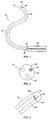
- catheter 10 is an elongated body which may be formed from a variety of materials, such as plastic and steel.
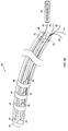
- Catheter 10 comprises an elongated body 12 having a distal end 14 adapted to be inserted into a bodily cavity, vessel, tract, or the like and a proximate end 16 available to a person performing a medical procedure.
- catheter 10 is shown to include a plurality of lumens 18, 20, and 22. While the catheter 10 is shown including three lumens 18, 20, and 22, those of ordinary skill in the art will readily recognize that this embodiment is merely illustrative to point out the features of the invention and that the number of lumens provided in any actual catheter fabricated according to the present invention and the uses therefore will depend solely on the end use to which catheter 10 will be put. Such a catheter may be steerable to be positioned by manipulation as is known in the art.
- an optical fiber 24 is disposed in lumen 18 of catheter 10.
- optical fiber 24 may have a diameter of approximately 0.025-0.051 cm (0.010-0.020 inch).
- An x-ray marker 26 preferably comprising a sensitive phosphor material or crystal, is optically coupled to a distal end 28 of the optical fiber 24.
- X-ray marker material 26 may comprise a material such as terbium-doped gadolinium oxysulfate (Gd 2 O 2 S 2 :Tb), available from USR Optronix, Inc.
- terbium doped gadolinium oxysulfate phosphor material in a finely ground powder form was both physically mounted and optically coupled to the distal 28 end of optical fiber 24 using an epoxy 30, such as QUIKSTIK, available from GC Electronics of Rockford, Illinois.
- the epoxy 30 was used to adhere the x-ray marker material 26 to the optical fiber 24 by placing a small amount of the epoxy 30 at the distal end of optical fiber 24 and then dipping the distal end 28 of optical fiber 24 into a finely divided phosphor powder. Similar techniques may be employed to affix a scintillating crystal to the distal end 28 of optical fiber 24.
- the epoxy 30 must be compatible with the phosphor material and must be optically clear at the phosphor emission wavelength.
- other methods for optically coupling the marker material to the optical fiber such as employment of a lens, are equivalent and fall within the scope of the present invention.
- a photodetector 32 is coupled to the proximate end 34 of optical fiber 24.
- the proximate end 34 of optical fiber 24 was coupled to the light-sensitive window of an RCA XT-2020 photomultiplier tube using a high viscosity clear silicone oil, such as available from Dow Corning Corporation of Midland, Michigan.
- an electrical signal will be generated in photodetector 32 when the catheter 10 of the present invention is exposed to x-ray radiation.
- Catheter 10 of the present invention is therefore highly useful when employed in applications with digital scanning beam x-ray apparatus, since the x-ray emission is in the form of discrete pixels, enabling location of the catheter's position with a high degree of accuracy.
- catheter 10 of FIGS. 1-3 is shown employing a single optically-coupled x-ray marker 26, catheters having a plurality of such optically coupled x-ray markers may be fabricated according to the principles of the present invention.
- the number of such markers employed in any actual embodiment of the catheter of the present invention will depend solely on the application for which the particular catheter is designed. Specific illustrative examples are disclosed herein.
- the present invention may be employed in a wide variety of both steerable and non-steerable catheters for various applications.
- catheters and applications will include multi-electrode catheters employed in electrophysiology, and catheters for ablation of cardiac arrhythmia, coronary atherocatheters, etc.
- the present invention will also be usefully employed, for example, in angioplasty balloon catheters, and in laparoscopy equipment.
- Such catheters now employ bands of radio-opaque material such as metal, so that they may be located by x-ray techniques during performance of angioplasty procedures.
- bands of radio-opaque material such as metal
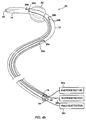
- FIGS. 4a-4c certain exemplary catheters employing the present invention will be disclosed.
- a multi-electrode electrophysiology catheter 40 for use in measuring intracardiac action potentials incorporates the present invention and is shown diagrammatically.
- An example of such a Commercial electrophysiology catheter of this type is Steerocath Model No. 2037 available from EP Technologies, Inc. of Mountain View, California.
- features of the catheter 40 which are the same as features of catheter 10 of FIGS. 1-3 are identified by the same reference numerals.
- catheter 40 is shown to include a plurality of lumens 18, 20, and 22.
- An optical fiber 24 is disposed in lumen 18 of catheter 10.
- An x-ray marker material 26 is affixed to a distal end 28 of the optical fiber 24.
- a plurality of conductive electrodes 42, 44, 46, and 48 are disposed in spaced-apart relationship near the distal end 14 of catheter 40. Electrodes 42, 44, 46, and 48 are individually electrically coupled to conductors 50, 52, 54, and 56, respectively. Conductors 50, 52, 54, and 56 are disposed in lumen 20 and emerge from its orifice at the proximate end 16 of catheter 40 and may be suitably connected to an electrophysiology recording and analysis system as is known in the art. As shown in FIG. 4a, a photodetector 32 is coupled to the proximate end 34 of optical fiber 24.
- angioplasty catheter 60 comprises an elongated body 12 having a distal end 14 adapted to be inserted into a bodily cavity, vessel, tract, or the like and a proximate end 16 available to a person performing a medical procedure.
- angioplasty catheter 60 includes an inflatable balloon 62 disposed near its distal end 14 which is used as is known in the art. Balloon 62 may be inflated from a lumen 64 with which it communicates. Angioplasty catheter 60 includes a central guidewire lumen 66 through which a guidewire is threaded as is known in the art.
- Angioplasty catheter 60 has advantages over prior art angioplasty catheters because it incorporates a plurality of x-ray markers as taught by the present invention.
- the embodiment illustrated in FIG. 4b shows three such x-ray markers 26a, 26b, and 26c, but those of ordinary skill in the art will recognize that an arbitrary number of markers could be employed if needed.
- x-ray marker 26a is disposed near the distal side of the balloon and x-ray marker 26b is disposed near the proximate side of the balloon.
- x-ray marker 26c is disposed further down the body 12 of the catheter towards its proximate end 16.
- X-ray markers 26a, 26b, and 26c are optically coupled to first ends of optical fibers 24a, 24b, and 24c, respectively.
- Optical fibers 24a, 24b, and 24c are shown disposed in individual lumens 18a, 18b, and 18c, although those of ordinary skill in the art will recognize that they might all be disposed in a single lumen if design considerations warranted such placement.
- Optical fibers 24a, 24b, and 24c are connected at their second ends to photodetectors 32a, 32b, and 32c.
- Those of ordinary skill in the art will recognize that the present invention represents a significant advantage over prior art catheters in which x-ray opaque bands are physically attached to selected positions of the catheter.
- the catheter of the present invention provides the advantage that the positions of the individual x-ray markers (and thus the position of balloon 62) may be uniquely and accurately determined due to their individual coupling to photodetectors 32a, 32b, and 32c.
- the present invention is easily interfaced to the widely used digital computer video equipment employed with modern x-ray systems so that, when used in conjunction with a scanning x-ray system, the positions of the x-ray markers may be indicated, for example, by blinking cursors, etc., avoiding the ambiguity which is characteristic of interpretation of x-ray displays to locate prior-art catheters.
- Atherocatheter 80 comprises an elongated body 12 having a distal end 14 adapted to be inserted into a bodily cavity, vessel, tract, or the like and a proximate end 16 available to a person performing a medical procedure.
- a central guidewire lumen 82 runs through the body of atherocatheter 80 from distal end 14 to proximate end 16 as is known in the art.
- a tapered coil spring 84 is typically internally disposed at the distal end 14 of atherocatheter 80 and functions to provide a stiff tapered end for the catheter in order to stretch the vessel in which it is placed.
- a rotating cutting section 86 comprises a cylindrical member axially disposed in the catheter body behind the tapered distal end 14.
- a cutting blade 88 is slidably mounted in rotating cutting section 86.
- Rotating cutting section 86 is coupled to a shaft 90 which runs through a lumen 92 and may be coupled to a motor for rotation.
- Atherocatheter 80 according to the present invention has advantages over prior art atherocatheters because it incorporates a plurality of x-ray markers as taught by the present invention.
- the embodiment illustrated in FIG. 4c shows three such x-ray markers 26a, 26b, and 26c, but those of ordinary skill in the art will recognize that an arbitrary number of markers could be employed if needed.
- x-ray marker 26a is disposed near the distal side of the rotating cutting section 86 and x-ray marker 26b is disposed near the proximate side of the rotating cutting section 86.
- x-ray marker 26c is disposed further down the body 12 of the catheter towards its proximate end 16.
- X-ray markers 26a, 26b, and 26c are optically coupled to first ends of optical fibers 24a, 24b, and 24c, respectively.
- Optical fibers 24a, 24b, and 24c are shown disposed in individual lumens although those of ordinary skill in the art will recognize that they might all be disposed in a single lumen if design considerations warranted such placement.
- Optical fibers 24a, 24b, and 24c are connected at their second ends to photodetectors 32a, 32b, and 32c.
- the catheter of the present invention provides the advantage that the positions of the individual x-ray markers (and thus of rotating cutting section 86) may be uniquely and accurately determined due to their individual coupling to photodetectors 32a, 32b, and 32c.
- the positions of the x-ray markers in atherocatheter 80 of FIG. 4c may be indicated, for example, by blinking cursors, etc., avoiding the ambiguity which is characteristic of interpretation of x-ray displays to locate prior-art catheters.
- the opening for the cutting blade is facing. This can be readily determined according to the present invention by partially shielding the x-ray marker material 26, for example, on three sides, leaving only approximately 90 degrees of rotation open to radiation. If more than one marker is shielded and the openings are oriented in different directions, an accurate assessment of catheter rotational orientation may be made.
- FIG. 4d is a top view of a plurality of x-ray markers according to the present invention. Although four x-ray markers are depicted in FIG. 4d, those of ordinary skill in the art will recognize that other numbers may be employed to affect the resolution with which the rotational position of the catheter may be determined.
- shielding member 90 is fabricated from a material which will block x-ray radiation having intensities encountered in the environments within which the catheter employing it will be used.
- shield member 90 may comprise, for example, tungsten having a thickness of about 0.025 cm (0.010 in.). It will be possible to utilize other materials and thicknesses because of the ability to compare the outputs of different photodetectors.
- Each of x-ray markers 26a, 26b, 26c, and 26d is separately connected to an optical fiber and a photodetector (not shown). In the configuration shown, each of the x-ray markers will be able to determine the rotational position of the catheter in which they are disposed to about a 90° resolution.
- top view comprising FIG. 4 does not indicate whether x-ray markers 26a, 26b, 26c, and 26d are disposed at the same point along the length of the catheter in which they are placed. This does not matter and will be a matter of design choice, subject of course to the inaccuracy which would result from twisting of the catheter if they are disposed at different positions along the length of the catheter.
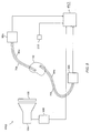
- FIGS. 5 and 6 illustrative uses of catheter 10 of the present invention are shown.
- a digital scanning beam x-ray system 100 is shown employed with catheters 70a and 70b shown disposed in a volume 102.
- volume 102 could be, for example, a patient into which catheters 70a and 70b have been inserted.
- Photodetectors 92a and 92b are coupled to the proximate ends of the optical fibers inside of catheters 70a and 70b respectively.
- Two catheters 70a and 70b, and their associated photodetectors 92a and 92b are shown for purposes of illustration, but those of ordinary skill in the art will recognize that any number of catheters and photodetectors may be employed according to the principles of the present invention.
- a scanning X-ray source emits radiation in the x-ray spectrum in a conventional manner using a scan pattern in the x-ray source 104 as is known in the art.
- a digital scan controller 106 controls the position of the beam spot on the face of the x-ray source 104 as is well known in the art.
- a grid 108 is positioned between the x-ray source 104, and an x-ray detector 110. The grid 108 ensures that x-ray emissions from selected pixel positions of the scanned x-ray tube 104 are directed to a focal point on x-ray detector 110 located behind the volume 102. The x-ray emissions detected by the detector 110 are used to generate a signal which is then sent to an image processor (not shown) for analysis.
- the emissions travel their various paths from the grid 108 to the detector 110, some of the emissions are intercepted by and irradiate the phosphor material disposed on the distal ends of optical fibers 84a and 84b in catheters 70a and 70b, respectively.
- the phosphor material responds by emitting light, which is directed down the optical fibers 84a and 84b to photodetectors 92a and 92b which convert the light to an electrical signal.
- the signal output from the photodetectors 92a and 92b will be at a maximum when the center of the cone of radiation which is allowed to pass through grid 108 is centered on the phosphor material each catheter.
- Control unit 112 is supplied with the x and y addresses from the scan controller 106 and with the output signals from photodetectors 92a and 92b.
- Control unit 112 which may be a well-known comparator and a well-known coincidence detector, correlates the output signals from photodetectors 32a and 32b with the scan address information from scan controller 106. This information may then be processed and thus may be used to determine the positions of the phosphor material in catheters 70a and 70b, and hence is an accurate indicator of the positions of the ends of the catheters themselves. It will be appreciated that the catheter positions can be located to within one or two pixel positions using the instant invention.
- two x-ray sources 104a and 104b employing independent scan controllers 106a and 106b, grids 108a and 108b, and x-ray detectors 110a and 110b may be used in combination with catheters 70a, 70b, and 70c, photodetectors 92a and 92b, and control unit 112 to accurately locate-the positions of the catheters 70a, 70b, and 70c in three dimensions by employing two of the catheters as reference catheters and a third as a mapping catheter whose position with respect to the other two catheters may be determined.
- the above-described embodiment of the present invention answers the long felt need for anatomical markers during cardiac diagnostic and treatment procedures.
- the alternative imaging modalities of MRI, CT, and ultrasound are not suitable for these procedures.
- the use of prior-art methods employing x-ray fluoroscopes for imaging has the serious disadvantage of not being able to distinguish anatomical detail inside the heart.
- the physician uses the shadows generated, his or her intimate knowledge of the anatomy, the characteristic movement of the image and catheters caused by the cardiac cycle and the respiratory cycle, and for fine positioning, the electrocardiogram.
- the initial work performed in this invention was to analyze the images from a biplane x-ray system when it was gated to the cardiac cycle. In some cases this positioning using image analysis is adequate but the precision can be greatly improved if a sensor is included in the catheter which is smaller than the smallest pixel in the output. With conventional image intensifier technology, such a point sensor would not be useful since the entire field of view is irradiated simultaneously.
- a scanning beam digital x-ray system the beam is divided such that each pixel is separated in time and therefore the location of the sensor in each individual catheter can be uniquely identified with a pixel.
- the sensor can be located in three dimensions provided that the two beams are synchronized. In cardiac applications, the cardiac cycle must be gated.
- the advantage of the above described medical catheter embodiment of the invention is that it permits existing catheters inside the patient to now also function as anatomical markers, significantly reducing the time to map and ablate. Additional advantages are more detailed mapping of the cardiac substrate, correlation of the intercardiac electrodes with anatomical location, display in three dimensions if desired of the intercardiac electrodes on an image of the heart, and comparison of electrograms from studies done at different times by overlaying.
Landscapes
- Health & Medical Sciences (AREA)
- Life Sciences & Earth Sciences (AREA)
- Engineering & Computer Science (AREA)
- Medical Informatics (AREA)
- Heart & Thoracic Surgery (AREA)
- Biomedical Technology (AREA)
- Biophysics (AREA)
- Veterinary Medicine (AREA)
- Public Health (AREA)
- General Health & Medical Sciences (AREA)
- Animal Behavior & Ethology (AREA)
- Radiology & Medical Imaging (AREA)
- Nuclear Medicine, Radiotherapy & Molecular Imaging (AREA)
- Molecular Biology (AREA)
- Surgery (AREA)
- High Energy & Nuclear Physics (AREA)
- Pathology (AREA)
- Optics & Photonics (AREA)
- Physics & Mathematics (AREA)
- Pulmonology (AREA)
- Anesthesiology (AREA)
- Hematology (AREA)
- Apparatus For Radiation Diagnosis (AREA)
- Media Introduction/Drainage Providing Device (AREA)
- Radiation-Therapy Devices (AREA)
- Endoscopes (AREA)
Claims (11)
- Röntgensensor zum Bestimmen der Lage eines zugehörigen Objekts in einem von einem Röntgen-Abtaststrahl erfaßten Bildwinkel, dadurch gekennzeichnet, daß diesereinen Röntgenmarker (26) aufweist, der mit einem Lichtleiter (24) optisch gekoppelt ist, wobei der Röntgenmarker durch Erzeugen eines optischen Signals auf Röntgenstrahlen anspricht, undeine Röntgen-Abschirmeinrichtung (90), die Röntgenstrahlen nur aus ausgewählten Richtungen selektiv zu dem Röntgenmarker (26) gelangen läßt.
- Röntgensensor nach Anspruch 1, wobei dieser ferner einen Fotodetektor (32) aufweist, der mit dem Lichtleiter gekoppelt ist und auf die optischen Signale anspricht.
- Röntgensensor-Katheter nach Anspruch 1 oder 2, wobei die Röntgenstrahlen-Abschirmeinrichtung (90) den Röntgenmarker (26) teilweise umhüllt.
- Röntgensensor-Katheter nach Anspruch 3, wobei die ausgewählten Richtungen von einem konischen Abschnitt festgelegt werden, der an dem Röntgenmarker eine Spitze aufweist.
- Röntgensensor-Katheter, dadurch gekennzeichnet, daß diesereinen Röntgensensor nach Anspruch 1 aufweist, fernereinen aus biegsamem Material geformten länglichen Körper (12), wobei der längliche Körper (12) ein distales Ende (14), ein proximales Ende und mindestens ein axial in seinem Inneren angeordnetes Lumen (18) aufweist, wobeider Lichtleiter (24) in dem wenigstens einen Lumen (18) angeordnet ist und ein distales Ende aufweist, das bezüglich des distalen Endes (14) des länglichen Körpers (12) an einer ausgewählten Stelle angeordnet ist, sowie ein proximales Ende, das dem proximalen Ende (16) des länglichen Körpers (12) zugeordnet ist, undder Röntgenmarker (26) an dem distalen Ende (14) des Lichtleiters (24) befestigt ist.
- Röntgensensor-Katheter nach Anspruch 5, wobei dieser ferner wenigstens eine leitfähige Elektrode (42) aufweist, die an einer Außenfläche des länglichen Körpers (12) in der Nähe von dessen distalem Ende (14) angeordnet ist, undeinen Leiter (50), der mit der wenigstens einen Elektrode elektrisch verbunden ist, wobei der Leiter durch das wenigstens eine Lumen (18) des länglichen Körpers (12) verläuft und an dem proximalen Ende (16) des länglichen Körpers (12) für einen elektrischen Anschluß daran zugänglich ist.
- Katheter nach Anspruch 5 oder 6, wobei der längliche Körper (12) eine Mehrzahl von axial in diesem angeordneten Lumina (18, 20, 22) aufweist, fernereine Mehrzahl der Röntgenmarker (24a, 24b, 24c), wobei jeder dieser Röntgenmarker in jeweils einem der Lumina (18, 20, 22) an einer ausgewählten Stelle entlang des länglichen Körpers angeordnet ist,eine Mehrzahl der Lichtleiter (24), wobei jeder dieser Lichtleiter in jeweils einem der Lumina (18, 20, 22) angeordnet ist und ein distales Ende (14) aufweist, das mit jeweils einem anderen der Röntgenmarker (24) optisch gekoppelt ist, sowie ein proximales Ende, das dem proximalen Ende des länglichen Körpers (12) zugeordnet ist, wobeidie Röntgen-Abschirmeinrichtungen (90) jedem der Röntgenmarker (24) zugeordnet sind, und jede der Röntgen-Abschirmeinrichtungen (90) den ihr zugeordneten Röntgenmarker (24) teilweise umhüllt.
- Katheter nach Anspruch 7, wobei die ausgewählten Richtungen aller Röntgen-Abschirmeinrichtungen (90) in gleichen Abständen voneinander auf einem Kreis liegen, der rechtwinklig zu einer dem länglichen Körper (12) parallelen Achse liegt, so daß man einen Hinweis auf die Rotationslage des Katheters erhält.
- Katheter nach Anspruch 5 oder 6, wobei dieser ferner einen Fotodetektor (32) aufweist, der mit dem proximalen Ende des Lichtleiters (24) gekoppelt ist und auf die optischen Signale anspricht.
- Röntgensensor-Katheter nach einem der Ansprüche 5 bis 9, wobei die Röntgen-Abschirmeinrichtung (90) den Röntgenmarker teilweise umhüllt.
- Röntgensensor-Katheter nach einem der Ansprüche 5 bis 10, wobei die ausgewählten Richtungen von einem konischen Abschnitt festgelegt werden, der an dem Röntgenmarker eine Spitze aufweist sowie eine rechtwinklig zu dem länglichen Körper liegende Achse hat.
Applications Claiming Priority (3)
| Application Number | Priority Date | Filing Date | Title |
|---|---|---|---|
| US845593A | 1993-01-25 | 1993-01-25 | |
| US8455 | 1993-01-25 | ||
| PCT/US1994/000957 WO1994016623A1 (en) | 1993-01-25 | 1994-01-25 | Catheter including an x-ray sensitive optical-sensor locating device |
Publications (3)
| Publication Number | Publication Date |
|---|---|
| EP0680277A1 EP0680277A1 (de) | 1995-11-08 |
| EP0680277A4 EP0680277A4 (de) | 1996-01-17 |
| EP0680277B1 true EP0680277B1 (de) | 1999-06-16 |
Family
ID=21731701
Family Applications (1)
| Application Number | Title | Priority Date | Filing Date |
|---|---|---|---|
| EP94907339A Expired - Lifetime EP0680277B1 (de) | 1993-01-25 | 1994-01-25 | Katheter mit röntgen-empfindlicher, optischer positionier-vorrichtung |
Country Status (7)
| Country | Link |
|---|---|
| EP (1) | EP0680277B1 (de) |
| JP (1) | JP3460839B2 (de) |
| AT (1) | ATE181223T1 (de) |
| AU (1) | AU6424194A (de) |
| DE (1) | DE69419134T2 (de) |
| IL (1) | IL108391A (de) |
| WO (1) | WO1994016623A1 (de) |
Families Citing this family (14)
| Publication number | Priority date | Publication date | Assignee | Title |
|---|---|---|---|---|
| KR19990064208A (ko) * | 1995-10-13 | 1999-07-26 | 트랜스바스큘라, 인코포레이티드 | 동맥 폐색부를 우회하고/거나 그 밖의 혈관 횡단 과정을 수행하기 위한 방법 및 장치 |
| DE10012639A1 (de) * | 2000-03-15 | 2001-09-20 | Walther Menhardt | Positionsinformationen durch Röntgen-optische Elemente |
| EP1502624B1 (de) * | 2000-08-17 | 2007-02-14 | William N. Borkan | Stimulationskatheter mit Elektrode und Faseroptik |
| AU2002317113A1 (en) * | 2001-07-05 | 2003-01-21 | Angiogene Inc. | Method and system for endovascular radiation detection |
| DE10141406B4 (de) | 2001-08-23 | 2008-01-17 | Siemens Ag | Verfahren und Vorrichtung zum Detektieren der dreidimensionalen Position eines in einem Körperbereich eingeführten Untersuchungsinstruments |
| JP4686484B2 (ja) | 2004-02-10 | 2011-05-25 | コーニンクレッカ フィリップス エレクトロニクス エヌ ヴィ | インターベンションデバイスの空間的ロードマップ生成方法、システム、及びその空間的精度を監視する品質管理システム |
| JP2004325461A (ja) * | 2004-06-07 | 2004-11-18 | Institute Of Physical & Chemical Research | 非ヒト由来の生体試料の特定部位検出方法、非ヒト由来の生体試料の生理学的測定方法、生体試料の特定部位検出装置、光ファイバ保持装置 |
| DE102007009177B4 (de) * | 2007-02-26 | 2015-09-24 | Siemens Aktiengesellschaft | Verfahren zu dreidimensionalen Lokalisation eines Instruments für einen interventionellen Eingriff sowie zugehörige Einrichtung |
| WO2009064845A2 (en) | 2007-11-16 | 2009-05-22 | Bernstein Eric F | Sterilizing compositions comprising phosphors for converting electromagnetic radiation to uvc radiation and methods for using the same |
| JP4634494B2 (ja) * | 2008-10-31 | 2011-02-16 | 独立行政法人 宇宙航空研究開発機構 | 放射線源位置検出システム、及び放射線源位置検出用プローブ |
| WO2012011914A1 (en) * | 2010-07-22 | 2012-01-26 | Hampton University | Apparatus and method for external beam radiation distribution mapping |
| GB201611819D0 (en) * | 2016-07-07 | 2016-08-17 | Univ Court Of The Univ Of Edinburgh The | Imaging method and apparatus |
| JP2019526369A (ja) | 2016-09-14 | 2019-09-19 | コーニンクレッカ フィリップス エヌ ヴェKoninklijke Philips N.V. | 光ファイバ付きの細長いデバイス |
| CN115279263A (zh) * | 2020-03-16 | 2022-11-01 | 圣犹达医疗用品国际控股有限公司 | 用于配准光学传感器参照系的系统和方法 |
Citations (1)
| Publication number | Priority date | Publication date | Assignee | Title |
|---|---|---|---|---|
| US5166073A (en) * | 1989-05-05 | 1992-11-24 | The Dow Chemical Company | Miniaturized sensor for ionizing radiation |
Family Cites Families (4)
| Publication number | Priority date | Publication date | Assignee | Title |
|---|---|---|---|---|
| US3992631A (en) * | 1975-02-27 | 1976-11-16 | International Diagnostic Technology, Inc. | Fluorometric system, method and test article |
| EP0255369A3 (de) * | 1986-08-01 | 1988-10-19 | Advanced Cardiovascular Systems, Inc. | Marker für Katheterspitze |
| DE3833365C2 (de) * | 1987-09-29 | 2000-12-07 | Biotronik Mess & Therapieg | Vorrichtung zum Ermitteln der räumlichen Ausrichtung eines medizinischen Katheters oder einer medizinischen Sonde |
| JPH0255904U (de) * | 1988-10-18 | 1990-04-23 |
-
1994
- 1994-01-20 IL IL10839194A patent/IL108391A/en not_active IP Right Cessation
- 1994-01-25 DE DE69419134T patent/DE69419134T2/de not_active Expired - Fee Related
- 1994-01-25 JP JP51731294A patent/JP3460839B2/ja not_active Expired - Fee Related
- 1994-01-25 AU AU64241/94A patent/AU6424194A/en not_active Abandoned
- 1994-01-25 EP EP94907339A patent/EP0680277B1/de not_active Expired - Lifetime
- 1994-01-25 WO PCT/US1994/000957 patent/WO1994016623A1/en not_active Ceased
- 1994-01-25 AT AT94907339T patent/ATE181223T1/de not_active IP Right Cessation
Patent Citations (1)
| Publication number | Priority date | Publication date | Assignee | Title |
|---|---|---|---|---|
| US5166073A (en) * | 1989-05-05 | 1992-11-24 | The Dow Chemical Company | Miniaturized sensor for ionizing radiation |
Also Published As
| Publication number | Publication date |
|---|---|
| WO1994016623A1 (en) | 1994-08-04 |
| IL108391A (en) | 2001-12-23 |
| DE69419134D1 (de) | 1999-07-22 |
| EP0680277A1 (de) | 1995-11-08 |
| AU6424194A (en) | 1994-08-15 |
| IL108391A0 (en) | 1994-04-12 |
| DE69419134T2 (de) | 2000-01-20 |
| JPH08508416A (ja) | 1996-09-10 |
| EP0680277A4 (de) | 1996-01-17 |
| ATE181223T1 (de) | 1999-07-15 |
| JP3460839B2 (ja) | 2003-10-27 |
Similar Documents
| Publication | Publication Date | Title |
|---|---|---|
| US5859893A (en) | X-ray collimation assembly | |
| EP3797691B1 (de) | 3d-darstellung der intrakardialen aktivität | |
| RU2764590C1 (ru) | Способ изображения внутрисердечной электрограммы | |
| JP4448194B2 (ja) | 医療用機器の診断及び取扱いならびに映像システム | |
| US8706195B2 (en) | Method for producing an electrophysiological map of the heart | |
| EP0775466B1 (de) | Mapping-Katheter | |
| JP4233798B2 (ja) | 患者の体からの複数の電気信号を測定する器械及び方法 | |
| RU2401067C2 (ru) | Устройство и способ направления катетера при электрофизиологических исследованиях | |
| JP6054031B2 (ja) | 蛍光透視データ表示機器 | |
| EP3119276B1 (de) | System zur verwendung von herzelektrogramminformationen der körperoberfläche kombiniert mit internen informationen zur bereitstellung einer therapie | |
| JP2004160212A5 (de) | ||
| IL108391A (en) | Catheter including an x-ray sensitive optical-sensor locating device | |
| US20060058663A1 (en) | System and method for marking an anatomical structure in three-dimensional coordinate system | |
| WO1995002995A1 (en) | Apparatus and method for treating cardiac arrhythmias | |
| JP2005342514A (ja) | 走査ビーム型x線画像システム | |
| US20070066889A1 (en) | Method for localizing a medical instrument introduced into the body of an examination object | |
| US20110208075A1 (en) | System and Method for Guide Wire Detection | |
| JP2009540935A (ja) | 対象物の位置を決定するためのシステムおよび方法 | |
| WO2020068266A1 (en) | Determining catheter-tip 3d location and orientation using fluoroscopy and impedance measurements | |
| Moorman et al. | Three-dimensional endocardial mapping system using a novel X-ray imager and locating catheter | |
| Karolyi et al. | Advanced Mapping and Navigation Techniques for Radiofrequency Ablation |
Legal Events
| Date | Code | Title | Description |
|---|---|---|---|
| PUAI | Public reference made under article 153(3) epc to a published international application that has entered the european phase |
Free format text: ORIGINAL CODE: 0009012 |
|
| 17P | Request for examination filed |
Effective date: 19950825 |
|
| AK | Designated contracting states |
Kind code of ref document: A1 Designated state(s): AT BE CH DE DK ES FR GB GR IE IT LI LU MC NL PT SE |
|
| A4 | Supplementary search report drawn up and despatched |
Effective date: 19951205 |
|
| AK | Designated contracting states |
Kind code of ref document: A4 Designated state(s): AT BE CH DE DK ES FR GB GR IE IT LI LU MC NL PT SE |
|
| 17Q | First examination report despatched |
Effective date: 19970912 |
|
| GRAG | Despatch of communication of intention to grant |
Free format text: ORIGINAL CODE: EPIDOS AGRA |
|
| GRAG | Despatch of communication of intention to grant |
Free format text: ORIGINAL CODE: EPIDOS AGRA |
|
| GRAG | Despatch of communication of intention to grant |
Free format text: ORIGINAL CODE: EPIDOS AGRA |
|
| GRAH | Despatch of communication of intention to grant a patent |
Free format text: ORIGINAL CODE: EPIDOS IGRA |
|
| GRAH | Despatch of communication of intention to grant a patent |
Free format text: ORIGINAL CODE: EPIDOS IGRA |
|
| GRAA | (expected) grant |
Free format text: ORIGINAL CODE: 0009210 |
|
| AK | Designated contracting states |
Kind code of ref document: B1 Designated state(s): AT BE CH DE DK ES FR GB GR IE IT LI LU MC NL PT SE |
|
| PG25 | Lapsed in a contracting state [announced via postgrant information from national office to epo] |
Ref country code: SE Free format text: THE PATENT HAS BEEN ANNULLED BY A DECISION OF A NATIONAL AUTHORITY Effective date: 19990616 Ref country code: NL Free format text: LAPSE BECAUSE OF FAILURE TO SUBMIT A TRANSLATION OF THE DESCRIPTION OR TO PAY THE FEE WITHIN THE PRESCRIBED TIME-LIMIT Effective date: 19990616 Ref country code: LI Free format text: LAPSE BECAUSE OF FAILURE TO SUBMIT A TRANSLATION OF THE DESCRIPTION OR TO PAY THE FEE WITHIN THE PRESCRIBED TIME-LIMIT Effective date: 19990616 Ref country code: IT Free format text: LAPSE BECAUSE OF FAILURE TO SUBMIT A TRANSLATION OF THE DESCRIPTION OR TO PAY THE FEE WITHIN THE PRE;WARNING: LAPSES OF ITALIAN PATENTS WITH EFFECTIVE DATE BEFORE 2007 MAY HAVE OCCURRED AT ANY TIME BEFORE 2007. THE CORRECT EFFECTIVE DATE MAY BE DIFFERENT FROM THE ONE RECORDED.SCRIBED TIME-LIMIT Effective date: 19990616 Ref country code: GR Free format text: LAPSE BECAUSE OF NON-PAYMENT OF DUE FEES Effective date: 19990616 Ref country code: ES Free format text: THE PATENT HAS BEEN ANNULLED BY A DECISION OF A NATIONAL AUTHORITY Effective date: 19990616 Ref country code: CH Free format text: LAPSE BECAUSE OF FAILURE TO SUBMIT A TRANSLATION OF THE DESCRIPTION OR TO PAY THE FEE WITHIN THE PRESCRIBED TIME-LIMIT Effective date: 19990616 Ref country code: BE Free format text: LAPSE BECAUSE OF FAILURE TO SUBMIT A TRANSLATION OF THE DESCRIPTION OR TO PAY THE FEE WITHIN THE PRESCRIBED TIME-LIMIT Effective date: 19990616 Ref country code: AT Free format text: LAPSE BECAUSE OF FAILURE TO SUBMIT A TRANSLATION OF THE DESCRIPTION OR TO PAY THE FEE WITHIN THE PRESCRIBED TIME-LIMIT Effective date: 19990616 |
|
| REF | Corresponds to: |
Ref document number: 181223 Country of ref document: AT Date of ref document: 19990715 Kind code of ref document: T |
|
| REG | Reference to a national code |
Ref country code: CH Ref legal event code: EP |
|
| REF | Corresponds to: |
Ref document number: 69419134 Country of ref document: DE Date of ref document: 19990722 |
|
| REG | Reference to a national code |
Ref country code: IE Ref legal event code: FG4D |
|
| PG25 | Lapsed in a contracting state [announced via postgrant information from national office to epo] |
Ref country code: PT Free format text: LAPSE BECAUSE OF FAILURE TO SUBMIT A TRANSLATION OF THE DESCRIPTION OR TO PAY THE FEE WITHIN THE PRESCRIBED TIME-LIMIT Effective date: 19990916 Ref country code: DK Free format text: LAPSE BECAUSE OF FAILURE TO SUBMIT A TRANSLATION OF THE DESCRIPTION OR TO PAY THE FEE WITHIN THE PRESCRIBED TIME-LIMIT Effective date: 19990916 |
|
| ET | Fr: translation filed | ||
| NLV1 | Nl: lapsed or annulled due to failure to fulfill the requirements of art. 29p and 29m of the patents act | ||
| REG | Reference to a national code |
Ref country code: CH Ref legal event code: PL |
|
| PG25 | Lapsed in a contracting state [announced via postgrant information from national office to epo] |
Ref country code: LU Free format text: LAPSE BECAUSE OF NON-PAYMENT OF DUE FEES Effective date: 20000125 Ref country code: IE Free format text: LAPSE BECAUSE OF NON-PAYMENT OF DUE FEES Effective date: 20000125 |
|
| PG25 | Lapsed in a contracting state [announced via postgrant information from national office to epo] |
Ref country code: MC Free format text: THE PATENT HAS BEEN ANNULLED BY A DECISION OF A NATIONAL AUTHORITY Effective date: 20000131 |
|
| PLBE | No opposition filed within time limit |
Free format text: ORIGINAL CODE: 0009261 |
|
| STAA | Information on the status of an ep patent application or granted ep patent |
Free format text: STATUS: NO OPPOSITION FILED WITHIN TIME LIMIT |
|
| 26N | No opposition filed | ||
| REG | Reference to a national code |
Ref country code: IE Ref legal event code: MM4A |
|
| REG | Reference to a national code |
Ref country code: GB Ref legal event code: IF02 |
|
| PGFP | Annual fee paid to national office [announced via postgrant information from national office to epo] |
Ref country code: FR Payment date: 20050117 Year of fee payment: 12 |
|
| PGFP | Annual fee paid to national office [announced via postgrant information from national office to epo] |
Ref country code: GB Payment date: 20050119 Year of fee payment: 12 |
|
| PGFP | Annual fee paid to national office [announced via postgrant information from national office to epo] |
Ref country code: DE Payment date: 20050228 Year of fee payment: 12 |
|
| PG25 | Lapsed in a contracting state [announced via postgrant information from national office to epo] |
Ref country code: GB Free format text: LAPSE BECAUSE OF NON-PAYMENT OF DUE FEES Effective date: 20060125 |
|
| PG25 | Lapsed in a contracting state [announced via postgrant information from national office to epo] |
Ref country code: FR Free format text: LAPSE BECAUSE OF NON-PAYMENT OF DUE FEES Effective date: 20060131 |
|
| PG25 | Lapsed in a contracting state [announced via postgrant information from national office to epo] |
Ref country code: DE Free format text: LAPSE BECAUSE OF NON-PAYMENT OF DUE FEES Effective date: 20060801 |
|
| GBPC | Gb: european patent ceased through non-payment of renewal fee |
Effective date: 20060125 |
|
| REG | Reference to a national code |
Ref country code: FR Ref legal event code: ST Effective date: 20060929 |