EP0680667B1 - Koronaentladungsvorrichtung - Google Patents
Koronaentladungsvorrichtung Download PDFInfo
- Publication number
- EP0680667B1 EP0680667B1 EP94905446A EP94905446A EP0680667B1 EP 0680667 B1 EP0680667 B1 EP 0680667B1 EP 94905446 A EP94905446 A EP 94905446A EP 94905446 A EP94905446 A EP 94905446A EP 0680667 B1 EP0680667 B1 EP 0680667B1
- Authority
- EP
- European Patent Office
- Prior art keywords
- signal
- frequency
- pulse
- pwm
- gating
- Prior art date
- Legal status (The legal status is an assumption and is not a legal conclusion. Google has not performed a legal analysis and makes no representation as to the accuracy of the status listed.)
- Expired - Lifetime
Links
- 238000004804 winding Methods 0.000 claims abstract description 42
- 239000003990 capacitor Substances 0.000 claims abstract description 20
- 238000012360 testing method Methods 0.000 claims abstract description 5
- 238000000034 method Methods 0.000 claims description 8
- 230000004044 response Effects 0.000 claims description 4
- 230000000994 depressogenic effect Effects 0.000 claims description 2
- 230000001131 transforming effect Effects 0.000 claims 6
- 230000000737 periodic effect Effects 0.000 claims 4
- 230000001965 increasing effect Effects 0.000 abstract description 8
- 238000002560 therapeutic procedure Methods 0.000 abstract description 3
- 238000010586 diagram Methods 0.000 description 8
- 230000009977 dual effect Effects 0.000 description 8
- 230000001225 therapeutic effect Effects 0.000 description 8
- 229910000859 α-Fe Inorganic materials 0.000 description 7
- 230000000903 blocking effect Effects 0.000 description 4
- 239000004020 conductor Substances 0.000 description 4
- 239000000523 sample Substances 0.000 description 4
- 238000006243 chemical reaction Methods 0.000 description 3
- 230000004048 modification Effects 0.000 description 3
- 238000012986 modification Methods 0.000 description 3
- 230000008569 process Effects 0.000 description 3
- 230000001681 protective effect Effects 0.000 description 3
- 230000003252 repetitive effect Effects 0.000 description 3
- 230000000630 rising effect Effects 0.000 description 3
- 238000009966 trimming Methods 0.000 description 3
- 206010061218 Inflammation Diseases 0.000 description 2
- 241001024304 Mino Species 0.000 description 2
- 206010003246 arthritis Diseases 0.000 description 2
- 230000003247 decreasing effect Effects 0.000 description 2
- 230000004054 inflammatory process Effects 0.000 description 2
- 230000007774 longterm Effects 0.000 description 2
- 238000005259 measurement Methods 0.000 description 2
- 238000000015 thermotherapy Methods 0.000 description 2
- 229910000906 Bronze Inorganic materials 0.000 description 1
- 229920004943 Delrin® Polymers 0.000 description 1
- XUIMIQQOPSSXEZ-UHFFFAOYSA-N Silicon Chemical compound [Si] XUIMIQQOPSSXEZ-UHFFFAOYSA-N 0.000 description 1
- 230000004075 alteration Effects 0.000 description 1
- 230000009286 beneficial effect Effects 0.000 description 1
- 230000008901 benefit Effects 0.000 description 1
- 239000010974 bronze Substances 0.000 description 1
- 239000000919 ceramic Substances 0.000 description 1
- 238000010276 construction Methods 0.000 description 1
- KUNSUQLRTQLHQQ-UHFFFAOYSA-N copper tin Chemical compound [Cu].[Sn] KUNSUQLRTQLHQQ-UHFFFAOYSA-N 0.000 description 1
- 230000001419 dependent effect Effects 0.000 description 1
- 230000000881 depressing effect Effects 0.000 description 1
- 230000005611 electricity Effects 0.000 description 1
- 230000002708 enhancing effect Effects 0.000 description 1
- 230000005669 field effect Effects 0.000 description 1
- 230000035876 healing Effects 0.000 description 1
- 238000009413 insulation Methods 0.000 description 1
- 238000012423 maintenance Methods 0.000 description 1
- 238000004519 manufacturing process Methods 0.000 description 1
- 230000002250 progressing effect Effects 0.000 description 1
- 230000003134 recirculating effect Effects 0.000 description 1
- 238000011084 recovery Methods 0.000 description 1
- 238000007493 shaping process Methods 0.000 description 1
- 230000035939 shock Effects 0.000 description 1
- 229910052710 silicon Inorganic materials 0.000 description 1
- 239000010703 silicon Substances 0.000 description 1
- 239000007787 solid Substances 0.000 description 1
Images


Classifications
-
- A—HUMAN NECESSITIES
- A61—MEDICAL OR VETERINARY SCIENCE; HYGIENE
- A61N—ELECTROTHERAPY; MAGNETOTHERAPY; RADIATION THERAPY; ULTRASOUND THERAPY
- A61N1/00—Electrotherapy; Circuits therefor
- A61N1/10—Applying static electricity
-
- H—ELECTRICITY
- H01—ELECTRIC ELEMENTS
- H01T—SPARK GAPS; OVERVOLTAGE ARRESTERS USING SPARK GAPS; SPARKING PLUGS; CORONA DEVICES; GENERATING IONS TO BE INTRODUCED INTO NON-ENCLOSED GASES
- H01T19/00—Devices providing for corona discharge
- H01T19/04—Devices providing for corona discharge having pointed electrodes
Definitions
- the present invention relates to corona discharge apparatus including electric power amplifiers, especially suitable for use in medical and veterinary testing and therapy.
- a corona discharge beam is a discharge of electricity produced on the surface of and adjacent to a conductor when the voltage gradient produced by a high voltage exceeds a certain critical value due to ionization of the surrounding air by the high voltage.
- Corona discharge beams for use in thermotherapy treatment in general and for use in trimming thick film resistors are known in the art.
- U.S. Patent No. 4,667,677 discloses a thermotherapy technique in which a beam is used to apply heat to a patient's skin to treat arthritis and other medical conditions.
- a corona discharge beam is derived from a low radio-frequency power source in which a low radio-frequency carrier in the range of 200 to 300 kHz is overmodulated by a sonic frequency signal in the 3000 to 5000 Hz range to produce a continuous energy waveform.
- the resulting bursts of radio-frequency energy have a repetition rate at the sonic frequency and a peak amplitude sufficient to cause a corona discharge in the energy range of 5 to 15 watts.
- the energy from this discharge is applied in 20 second and 30 to 40 second applications to generate heat in a patient.
- U.S. Patent No. 4,714,911 discloses a technique for enhancing the electrical characteristics of thick film resistors to bring them to their target values.
- a generating unit in which a low radio-frequency carrier is overmodulated by a sonic signal to produce bursts of radio-frequency energy which is coupled to an UP probe by a step-up transformer and to a DOWN probe by a step-down transformer.
- U.S. Patent No. 5,131,904 discloses a method of treating arthritis by placing the affected body part in the field of an annular coil driven by a rectangular waveform.
- corona discharge to treat mammalians has been known since at least the beginning of the twentieth century, as evidenced by the work of Nicola Tesla as told by Margaret Cheney in TESLA: Man Out of Time (Dell, 1981).
- the use of sonic frequencies to produce the energy wave to create a corona discharge have also been reported. It is clear from these references that the therapeutic use of corona discharge in general is recognized.
- the known applications of corona discharge emphasize the healing effect of the heat generated by the corona discharge, a secondary result of the application of the corona discharge to a treatment area, and in only a limited way appreciate that the corona energy in and of itself, or the magnetic fields associated with the corona discharge and generated by the corona discharge apparatus in conjunction with the discharge as a result of the particular waveforms employed, may be important in creating a therapeutic benefit.
- the known applications of corona discharge to mammalian therapeutic uses is limited by the lack of understanding of how to employ particular waveforms and how to generate suitable corona discharges, including the magnetic fields which are associated therewith, that have beneficial uses from such waveforms, in addition to any thermotherapeutic utility.
- the present invention solves the problems of known systems.
- the apparatus includes a coil of special construction.
- the invention is safe and easy to use, flexible, conveniently adjustable, and is light-weight and portable due to preferred use of battery power as well as embodiments using AC power.
- the present invention provides an apparatus and method for generating specific signals so as to produce a corona discharge beam and magnetic fields for therapeutic treatment of medical conditions and veterinary testing. More particularly, the invention is useful in the treatment of pain and inflammation.
- a preferred embodiment of the present invention functions by employing a base frequency generator 100 which generates a 500 kHz square waveform.
- the generator 100 is connected to a pulse width modulator 110 for modulating the widths of the pulses of the base frequency wave.
- the modulator 110 is connected to a gate arrangement 120 which switches the modulated base frequency wave on and off repetitively in 660 Hz cycles in accordance with a duty cycle adjustment means and in accordance with a user's momentary trigger switch 124 and a timing circuit 126 responsive to the trigger switch.
- the gated, modulated base frequency wave enters a power driver element 130.
- the power driver element 130 provides power to a high-Q coil assembly 1, which coil assembly in turn provides high voltage to a corona discharge pin 320.
- the power driver 130 switches at 500 kHz and provides signals in the range of about 150 to 400 volts (depending on whether 120 VAC or 240 VAC input line power is used). Then, the 150-400 volt signal is stepped up to a range of 5-10 kilovolts, through use of a high-Q resonant circuit.
- a capacitor is connected in series with a primary winding of a transformer in series-resonant fashion.
- the secondary winding in coil assembly 1 has a 10:1 turns ratio with the primary, so that voltages of about 100 kilovolt are produced on the output of the secondary coil.
- FIG. 11 A preferred embodiment of the electronic power amplifier according to the present invention is shown and described in more detail with reference to FIGS. 1-10. Alterations to the first embodiment which are needed to form an alternative embodiment are shown in FIG. 11.
- FIGS. 1-5 a high-level functional description of the preferred embodiment of the invention is provided.
- the system includes a base frequency generator 100 which generates a square wave at approximately 500 kHz, as illustrated in FIG. 2.
- a suitable adjustment means such as a variable resistor 102, the exact frequency may be adjusted to equal the resonant frequency of a high-Q resonant circuit associated with the output transformer of the coil assembly 1.
- the base frequency generator is shown schematically, connected to a pulse width modulator (PWM) 110.
- PWM pulse width modulator
- the modulator 110 modulates the pulse widths of the 500 kHz wave generated by the base frequency generator 100, to adjust the power output of the entire apparatus.
- the width of pulses is adjustable by a suitable adjustment means such as a variable resistor 112. By increasing the width of the pulses, the long-term average output power is increased; conversely, by reducing the width of the pulses, the long-term average output power is decreased.
- the output of the pulse width modulator is shown in FIG. 3.
- the PWM output comprises a series of pulses of alternating polarity, but the individual pulses are narrower than a pure 500 kHz bipolar square wave. Between successive alternating-polarity pulses are periods of zero volt output. The zero volt periods are shorter when the pulses are longer, and are longer when the pulses are shorter. Regardless of the pulse widths, the overall waveform has a repetition frequency of 500 kHz.
- the base frequency generator 100 and pulse width modulator 110 may collectively be implemented as a SILICON GENERAL SG3525 PWM generator or equivalent, an off-the-shelf integrated circuit which is commonly used in switching power supplies.
- a potentiometer 102 for adjusting the generator's output frequency, as well as a potentiometer 112 for adjusting its output pulse width, are used directly with the SG3525.
- the pulse width modulated 500 kHz wave enters a gate 120, which gates its input (reduces to zero amplitude) at a 660 Hz rate.
- the gate 120 effectively gates the 500 kHz pulse-width modulated signal of FIG. 3 against a gating wave (preferably 50% duty cycle) gating signal of 660 Hz.
- the envelope of the resultant gated waveform is shown in FIG. 4.
- the frequency as well as the duty cycle of the gate's effective gating signal is adjustable by suitable adjustment means 122, as described in greater detail below.
- the pulse-width modulated signal is gated, either by the user removing his finger from the switch 124, by timeout of a timer circuit 126 responsive to the user switch, or by the "off" portion of the repetitive pulse train determined by duty cycle adjustment means 122.
- This logic, wave shaping and gating is done at the logic power level (such as 12-13 volts), thus conserving power.
- the gated 500 kHz wave of FIG. 4 is fed into power driver 130.
- Power driver 130 preferably includes MOSFETs and fast-recovery diodes which are connected in a half bridge or bridge topology, so as to operate as power switches.
- the output of the power switches is a square wave which corresponds to the gated, pulse-width modulated signal output by the gate 120.
- the power switches switch at 500 kHz, and provide output in the range of 150 to 400 volts depending upon whether 120 VAC or 240 VAC is used to power the apparatus.
- the 150-400 volt signal from power driver 130 is stepped up to a range of 5 to 10 kilovolts by an LC network having the 150 volt square wave voltage input to it.
- the power driver 130 is connected to a capacitor 140 which is in series resonant arrangement with the primary winding 150 of a transformer having a primary winding 150 and a secondary winding 170.
- the high-Q properties of the resonant circuit permit the higher-voltage (5-10 kV) sinusoidal signal to be formed at node 145.
- the primary winding 150 is grounded to power supply ground at 154.
- the primary winding 150 is electrically connected to the secondary winding 170 at node 145, and is also magnetically coupled to it by a ferrite core 160.
- the primary and secondary windings are wrapped around the ferrite core 160.
- the ferrite core increases the Q of the LC circuit as seen by power driver 130.
- the transformer has a 10:1 turns ratio so as to step up the primary voltage so that the secondary winding provides a high voltage (about 100 kV) output signal.
- the secondary winding is "air grounded” at 174 through a discharge pin 320.
- the secondary winding produces the voltage in the 30 kilovolt to 200 kilovolt range, resulting in the desired corona discharge beam.
- Charge gathers at the end of the discharge pin, which is preferably configured as a conductive (preferably bronze) rod.
- an exemplary illustrated coil assembly 1 and associated discharge pin 320, resonant circuit node leads 145, the connection to power supply ground 154, and the trigger switch 124 are illustrated within a housing 200. Also illustrated are insulative support structures 310, 311 in the barrel 340 of the apparatus.
- the leads in node 145 to the primary and secondary coils, the return ground 154 wire, and the leads 224 from momentary switch 124, are all passed within a protective sheathing 270.
- the leads in node 145 to the primary and secondary coils, and the return ground 154 wire are respectively connected to the inner conductor and outer conductor of a co-axial cable 272 within the protective sheathing 270.
- the opposite end of the protective sheathing 270 is connected to a cabinet (not shown) that includes other elements of the embodiment shown in FIG. 1.
- elements 100-140 are in the cabinet, with only the coil assembly 1 and discharge pin 320 being in the hand-held corona discharge unit.
- the capacitor 140 may be included not in the cabinet, but rather in the hand-held unit.
- FIG. 7 is a top view showing a preferred embodiment of the coil assembly, along line 7-7 of FIG. 6.
- FIG. 8 is a side sectional view of the coil assembly according to the embodiment of FIG. 6.
- the coil assembly is arranged in a substantially radial fashion, with the substantially cylindrical ferrite core 160 at its center.
- the ferrite core 160 is at ground potential.
- voltage increases with increasing distance from the center, with the highest voltage at the outermost portion of the assembly.
- the coil assembly is constructed in layers, as seen most easily in FIG. 8.
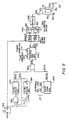
- FIG. 9 is a block diagram schematically illustrating a preferred embodiment of the corona discharge apparatus.
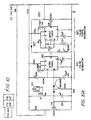
- FIGS. 10A, 10B, and 10C (collectively referred to as FIG. 10 herein, for brevity) comprise a detailed circuit level diagram of the embodiment shown functionally in FIG. 1 and schematically in FIG. 9.
- FIG. 9 thus provides a closer representation of the structure shown in the detailed circuit diagram in FIG. 10, than does the very general functional diagram in FIG. 1.
- switch 124 is shown as a momentary switch which shorts a positive constant voltage to a first input of an AND gate 912.
- AND gate 912 provides a gated switch signal to a 20-second ON-time pulse generator 910.
- the ON-time pulse generator 910 effectively functions as a monostable multivibrator, providing non-inverting and inverting outputs 910Q and 910Q-, respectively.
- pulse generator 910 is called an ON-time pulse generator because, during the 20-second "window" defined by its output pulse, the output coil of the apparatus may be on. At times when the 20-second pulse is inactive, the coil cannot be on.
- the inverted 20-second output pulse is fed back to a second input of the AND gate 912, to schematically illustrate that the ON-time pulse generator does not operate as a re-triggerable pulse generator. That is, after a first rising edge is encountered at the input of the pulse generator, signal 910Q- blocks any further rising edges that are caused by any repeated depressions of switch 124, from causing the pulse generator from beginning a new 20-second pulse.
- inverted output signal 910Q- triggers a second pulse generator 914, which operates as a monostable multivibrator.
- Pulse generator 914 outputs a 10-second inverted pulse 914Q- to a third input of AND gate 912. This 10-second pulse thus extends by 10 seconds the input gating function provided by the 20-second pulse 910Q-. It is understood that FIG.
- monostable multivibrator 914 has zero delay time, so that the two blocking pulses on respective paths 910Q- and 914Q- are deemed contiguous to form a continuous 30-second blocking function, and do not allow a "gap" between the two blocking signals to re-trigger pulse generator 910.
- a single 20-second period defined by a pulse at output 910Q, followed by a 10-second period defined by a pulse at output 914Q- ensure that no further pulse can be generated. Accordingly, single or repeated depressions of switch 124 during a thirty second period result in a 20-second 910Q pulse followed by at least a 10-second absence of a 910Q pulse. After this 30-second period, new or continued depression of the switch 124 may cause another 20-second-pulse/10-second-absence.
- the signal on path 910Q is provided to a first input of an AND gate 930.
- a second input of AND gate 930 receives a repetitive gating signal on path 920Q generated from a pulse train generator 920.
- Pulse train generator 920 provides a repetitive series pulses of time duration t on with intermediate off periods of duration t off therebetween.
- t on t off to provide a square wave, with t on + t off representing a pulse train period of 1515.1 ⁇ s, corresponding to a pulse repetition frequency period of 660 Hz.
- Respective t on and t off adjustment means 921 and 922, such as adjustable resistors, are illustrated. Adjustment means 921 and 922 collectively correspond to duty cycle adjustment means 122 (FIG. 1).
- AND gate 930 gates the 660 Hz pulse train on path 920Q against the 20-second pulse on path 910Q.
- the output of AND gate 930 is essentially the same as the signal on path 920Q, having a duty cycle determined by the settings of adjustment means 921, 922 (122 in FIG. 1).
- the output of AND gate 930 is also a square wave for the duration of the 20-second period.
- AND gate 930 enables a frequency-tunable pulse width modulator (also referred to as a PWM generator) 940.
- PWM generator 940 When active, PWM generator 940 generates a digital pulse train such as that shown in FIG. 3, having a frequency determined by frequency tuning means 102, and of pulse width determined by width adjustment means 112.
- the pulse frequency is about 500 kHz, finely tunable to match the resonant frequency of the LC circuit including capacitor 140 and primary winding 150.
- the pulse width is adjusted by the user as needed to provide more output power.
- opposite-polarity pulse trains are provided on respective paths 940Q and 940Q-.
- Each of these signals is represented by a waveform such as that shown in FIG. 3, gated by a 660 Hz signal so that it is represented by FIG. 4.
- the signal in FIG. 3 is output by the PWM generator only when the pulse train on path 920Q is high; if the signal on path 920Q is between pulses, AND gate 930 disables the PWM generator so that its output goes to zero as shown in FIG. 4.
- the PWM generator when there is no 20-second pulse on path 910Q, the PWM generator is disabled. Only for the duration of any 20-second pulse on path 910Q does the PWM generator generate a 500 kHz signal, and then, only during the ⁇ s "on" time periods of the 660 Hz enabling pulse train on path 920Q.
- Dual gating device 950 includes two gates 951 and 952 which receive the signals on paths 940Q and 940Q-, respectively. Both gates 951, 952 of dual gating device 950 are enabled by closure of momentary switch (user push button) 124.
- momentary switch user push button
- the gated, opposite-polarity 500 kHz pulse width modulated signals on paths 940Q and 940Q- pass through the gates 951, 952, only at instants when the user is depressing the momentary switch (trigger) 124.
- the user may almost instantaneously remove power from the coils by disabling the outputs of gating device 950.
- Half-bridge power switch arrangement 960 includes two series-connected power switches 961, 962 disposed between a higher voltage (such as 160 V) than the voltage (such as 13 VDC) used by the logic in elements 910-950.
- power switches 961, 962 When enabled, power switches 961, 962 collectively cause generation of an exponentially increasing sine wave in the high-Q LC circuit 140/150.
- the exponentially increasing sine wave is generated in the high-Q circuit constituting capacitor 140 and primary coil 150, through a recirculating means schematically illustrated as element 965.
- the sine wave builds exponentially to the 5 kV to 10 kV range at the input of the primary winding 150, the exact range being dependent on the Q of the LC circuit comprising capacitor 140 and primary winding 150.
- the voltage provided by the secondary winding 170 to the corona discharge pin 320 is determined by the turns ratio (such as 10-1) of the secondary winding to the primary winding. In the preferred embodiment, the voltage across the secondary, which corresponds to the voltage from the discharge pin 320 to "air ground" 174, is approximately 100 kV.
- adjustment means 102 and 112 are readily accessible to the user.
- the frequency adjustment means 102 is aptly labelled “TUNE” near a rheostat knob or the like.
- the pulse width adjustment means 112 is aptly labelled “POWER” near another rheostat knob or the like.
- gating pulse train duty cycle adjustment means 921, 922 (122) are preferably located inside a cabinet of the apparatus, so that they are not readily accessible to the user. Gating pulse train adjustment means 921, 922 (122) are set at the time of manufacture or for maintenance purposes by individuals who are generally more skilled than end users. Gating pulse train adjustment means 921, 922 (122) effectively determine a settable maximum power available to the device, with POWER knob 112 controlled by the user to adjust instantaneous output power from zero to that maximum. In this manner, gating pulse train adjustment means 921, 922 (122) ensure that, even at the maximum POWER setting on element 112, no elements will be burned out by the user.
- the elements in FIG. 9 may be located in a variety of ways.
- the electronics shown as elements 910 through 965 are located in a suitable cabinet (now shown) separate from the hand-held unit shown in FIG. 6.
- the capacitor 140 may be located either in the cabinet, or in the handle of the hand-held unit, as desired.
- a suitable cable joining the cabinet to the hand-held unit must carry high voltages if the capacitor is located in the cabinet rather than in the hand-held unit.
- the hand-held unit can be made lighter and more compact by locating the capacitor in the cabinet.
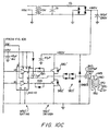
- FIGS. 10A-10C are a detailed circuit diagram of the embodiment shown more functionally in FIG. 9. Given the foregoing detailed description of FIG. 9, those skilled in the art will readily appreciate the function of the detailed disclosure in FIGS. 10A-10C. Thus, the following description is provided for convenience in facilitating an understanding of the non-limiting embodiment described herein.
- the push button (momentary switch) 124 is illustrated.
- a 2N2222 transistor is turned on by closure of the switch, and provides an inverting function to enable (active low enable) the dual gating arrangement 950 (FIG. 10C).
- the gating arrangement 950 is implemented as an INTERNATIONAL RECTIFIER IR 2110 driver/voltage translator.
- the first "555 timer" 910' has its pin 6 connected to an intermediate node of an RC timing network which governs the 20-second and 10-second timing pulses shown symbolically in FIG. 9.
- the 44 ⁇ F capacitor connected to ground is a timing capacitor, with the discharge path through the 100 k ⁇ resistor governing the 10-second blocking pulse shown symbolically on path 914Q- (FIG. 9).
- the second "555 timer" 920' is a free-running timer generating the 660 Hz, preferably square wave, pulse train on path 920Q (FIG. 9).
- Rheostats 921, 922 have exact analogs in FIG. 9.
- the AND gate 930 (FIG. 9) is embodied by a joining of the wire outputs of the two "555 timers" 910', 920'. This joining effectively performs a gating function at the input to pulse width generator 940' (FIG. 10B).
- pulse width generator 940' is preferably implemented using an SG3525A or equivalent.
- TUNE and POWER rheostats 102, 112 find analogs 102', 112' in FIG. 10B.
- circuitry devoted to converting 115 VAC power into 13 VDC power for use as a DC power supply for the digital circuitry is also illustrated in FIG. 10B.
- the invention provides that DC battery power may also be used to power the device, in which case the illustrated AC-DC conversion circuitry may be replaced by suitable DC power circuitry.
- the dual gate arrangement 950' is shown, implemented as an IR2110.
- the dual gate arrangement 950' drives respective FETs (field effect transistors) 961', 962' within half bridge driver 960'.
- a central node between the FETs of half-bridge driver 960' drives the high-Q circuit 140/150 through an arrangement of four fast diodes collectively indicated as recirculation means 965'.
- the diodes are arranged in a figure "8" configuration, with the half-bridge's intermediate node and capacitor being connected to the extreme ends of the "8".
- two fast diodes connect in series (1) ground potential, (2) the node between the recirculation means 965' and the capacitor 140, and (3) the +160 V node.
- Respective diodes connect the source to the drain of each of the two FETs 961', 962', to by-pass the FETs on one direction.
- the 160 V level is generated by a conversion circuit receiving 115 VAC power, the details of which are not central to the present invention.
- the invention provides that DC battery power may also be used to power the device, in which case the illustrated AC-DC conversion circuitry may be replaced by suitable circuitry for producing the 160 V level.
- the FET switches 961', 962' are turned on and off in opposite phase, controlled by the (approximately) 500 kHz square wave signals input to their respective gates.
- the high-Q properties of the resonant circuit allow it to support a cumulatively increasing voltage as fed by the two FETs in successive half-cycles of the 500 kHz waveform.
- FET 961' is turned on during a first half of a first cycle of the 500 kHz waveform, causing node 145 to achieve a first voltage of a first polarity. Then, during the second half of the first 500 kHz cycle, FET 962' causes the node to achieve a second voltage twice that of the first, but of opposite polarity. During the first half of a second cycle of the 500 kHz switching signal, the first FET 961' causes the node to achieve to a third voltage larger in magnitude than the second voltage, but in the first polarity. During the second half of the second cycle, the second FET 962' causes the node to achieve a fourth voltage greater in magnitude than the third voltage, in the second polarity.
- the invention also provides a self-tuning embodiment to ensure that the frequency of the PWM generator is maintained at the resonant frequency of the LC circuit 140, 150.
- the self-tuning feature ensures that no manual adjustment of frequency of the PWM generator 940 is necessary. This implies that the TUNE (frequency adjustment) knob 102 is not necessary.
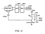
- FIG. 11 Modifications of the manual tuning embodiment required to convert it to the self-tuning embodiment are shown in FIG. 11.
- a resistor R st is inserted between the primary winding 150 and power supply ground 154.
- the resistor is effectively used to measure the current passing through the primary winding.
- the node between the resistor and the primary winding is used as a measurement output.
- a capacitor extends to ground from pins 5 and 7 of the SG3525A PWM generator.
- the formerly grounded end of the capacitor is connected directly to the measurement output of the primary winding, as shown in FIG. 11.
Landscapes
- Health & Medical Sciences (AREA)
- Engineering & Computer Science (AREA)
- Physics & Mathematics (AREA)
- Plasma & Fusion (AREA)
- Radiology & Medical Imaging (AREA)
- Life Sciences & Earth Sciences (AREA)
- Animal Behavior & Ethology (AREA)
- General Health & Medical Sciences (AREA)
- Public Health (AREA)
- Veterinary Medicine (AREA)
- Biomedical Technology (AREA)
- Nuclear Medicine, Radiotherapy & Molecular Imaging (AREA)
- Inverter Devices (AREA)
- Physical Or Chemical Processes And Apparatus (AREA)
- Magnetic Resonance Imaging Apparatus (AREA)
- Plasma Technology (AREA)
- Electrotherapy Devices (AREA)
- Electrical Discharge Machining, Electrochemical Machining, And Combined Machining (AREA)
- Electrostatic Separation (AREA)
- Testing Relating To Insulation (AREA)
- Magnetic Treatment Devices (AREA)
Claims (3)
- Koronaentladungsvorrichtung für medizinischen Gebrauch, wobei ein Hochfrequenzsignal (rf) bei niedriger (Schall-) Frequenz ein/aus moduliert ist, so dass Impulse bestehend aus Hochfrequenz-Pulsen erhalten werden, dadurch gekennzeichnet, dass sie umfasst:Mittel (100, 110) zum Erzeugen eines elektrischen Signals bestehend aus niederfrequenten Impulsen die bestehen aus hochfrequenten, breitenmodulierten Pulsen, wobei die Mittel zum Erzeugen des elektrischen Signals umfassen:einen pulsbreiten Modulations (PWM) Generator (110) zum Erzeugen eines PWM Ausgangssignals, wobei der PWM Generator enthält:1) Mittel (102) zum Einstellen einer Frequenz des PWM Ausgangssignals, die derart angeordnet sind, dass sie für den Benutzer der Vorrichtung leicht zugänglich sind; und2) Mittel (112) zum Einstellen der Breite von Pulsen im PWM Ausgangssignal, die derart angeordnet sind, dass sie für den Benutzer leicht zugänglich ist;einen Momentanschalter (124), der derart angeordnet ist, dass er für den Benutzer leicht zugänglich ist; Zeitschaltmittel (910), die auf den Momentanschalter (124) ansprechen, um ein Fenstersignal für bloss eine gegebene Periode unmittelbar nach dem Drücken des Momentanschalters zu erzeugen;ein Pulsketten-Torsteuerungs-Generatormittel (914) zum Erzeugen einer Pulskette einer Frequenz, die wesentlich unterhalb der Frequenz des PWM Ausgangssignals ist, wobei die Pulskette periodisch Einschaltperioden aufweist;UND-Gattermittel (912) zum Empfang(1) des Fenstersignals von Zeitschaltmittel und (2) die Pulskette vom Pulsketten-Torsteuerungs-Generatormittel, und zum Einschalten des PWM Generators (110) nur während dem gleichzeitigen Erscheinen des Fenstersignals und der Einschaltperiode;Torschaltmittel (950) zum Schalten des PWM Ausgangssignals wann immer der Momentanschalter nicht gedrückt ist; und ein Treibermittel (960), das auf das Torschaltmittel (950) anspricht, um ein Treibersignal zu erzeugen, das kennzeichnend ist für das PWM Ausgangssignal, wenn das Torschaltmittel (950) das PWM Ausgangssignal nicht weiter schaltet;Ein Transformermittel (130, 140, 150, 170) zum transformieren des Signals in ein Hochspannungssignal, dessen Leistungsgrösse direkt mit der Pulsbreite variiert, wobei das Transformermittel umfasst:Einen Kondensator (140), der zwischen dem Treibermittel und einer Spulen-Baugruppe (150) angeordnet ist; Eine Spulen-Baugruppe, die auf das Treibermittel anspricht und enthält:1) eine Primärspule (150), welche zusammen mit dem Kondensator (140) einen Schwingkreis bildet, der bei der Frequenz des PWM Generators resonant ist, wobei der Schwingkreis eine wesentliche Verstärkung der Spannung des Treibersignals bewirkt;2) einen im wesentlichen zylindrischen Kern (160) der physikalisch um eine zentrale Achse angeordnet ist, um welche die Primärspule (150) lokalisiert ist; und3) eine Sekundärspule (170), die um die zentrale Achse gewunden ist mit einem Radius, der grösser als jener der Primärspule (150) ist, wobei die Sekundärspule (170) über den Kern (160) magnetisch mit der Primärspule gekoppelt ist und eine grössere Windungszahl aufweist als die Primärspule, um einen Transformatorausgang hoher Spannung zu erzeugen; und
wobei die besagten Mittel (320) zum Erzeugen der Koronaentladung eine Entladungsschaltung umfassen, die mit der Sekundärspule (170) verbunden ist, um den Hochspannungs-Transformatorausgang zu empfangen, so dass sie die Koronaentladung in einer Art erzeugen, die im wesentlichen gesteuert ist durch das Treibersignal und das PWM Ausgangssignal; undMittel (320) zum Erzeugen der Koronaentladung als Antwort auf das Hochspannungssignal. - Vorrichtung nach Anspruch 1, wobei die Mittel zum Erzeugen des elektrischen Signals umfassen:ein Mittel (100) zum Erzeugen eines ersten Frequenzsignals;ein Mittel (110) zum Impulsbreiten-Modulieren des ersten Frequenzsignals, um ein impulsbreiten-moduliertes Signal zu erzeugen; undein Mittel (120) zum periodischen Umschalten des impulsbreiten-moduliertren Signals mit einer zweiten Frequenz, die tiefer ist als die erste Frequenz, um ein getaktetes Signal enthaltend Impulse von breiten modulierten Pulsen bei der ersten Frequenz zu erzeugen; undwobei das Transformatormittel zum Transformieren des Signals in ein Hochspannungssignal Resonanzmittel (140, 150, 160) umfasst zum Umformen des getakteten Signals in ein Hochspannungssignal mit einer Leistung proportional zur modulierten Impulsbreite und zum Takt.
- Verfahren zum Erzeugen einer Koronaentladung der Art, wie sie für medizinische und veterinär-medizinische Tests verwendet und von der Modulation des ersten Frequenzsignals durch ein zweites Signal abgeleitet wird, umfassend:Erzeugen eines elektrischen Signals bestehend aus niederfrequenten Impulsen von hochfrequenten, breitenmodulierten Pulsen, wobei der Schritt des Erzeugens eines elektrischen Signals die Einzelschritte umfasst:Empfang eines Auslösesignals, welches das Schliessen eines Momentanschalters anzeigt, der von einem Benutzer betätigt wird;Erzeugen eines Fenstersignals als Antwort auf das Auslösesignal;Erzeugen eines periodischen Torsteuerungs-Signals mit einer Periode, die bedeutend kürzer ist als die Dauer des Fenstersignals,Erzeugen eines PWM Einschaltsignals beim gleichzeitigen auftreten des Fenstersignals und einer Einschalthöhe des periodischen Torsteuerungs-Signals;Erzeugen eines PWM Ausgangssignals beim Auftreten des PWM Einschaltsignals, wobei das PWM Ausgangssignal aus einer Serie von Impulsen von Pulsen einer Frequenz, die wesentlich höher ist als jene des periodischen Toresteuerungs-Signals und von einer Breite, die von einem pulsbreiten Einstellungsmittel bestimmt ist, welches für den Benutzer zugänglich ist;Umschalten des PWM Ausgangssignals unmittelbar wann immer das Auslösesignal nicht vorhanden ist; undErzeugen eines Treibersignals wann immer das PWM Signal erzeugt aber nicht durchgeschaltet ist; undTransformieren des Signals in einer Hochspannungs-Signal, dessen Grösse proportional ist zur Breite der Pulse, wobei der Schritt des Transformierens des Signals in einer Hochspannungs-Signal die folgenden Schritte umfasst:Umformen des Treibersignals in ein Zwischenspannungssignal, dessen Höhe grösser ist als das PWM Signal, unter Benutzung eines in Serie geschalteten Resonanz-Schwingkreises mit einer Resonanzfrequenz im wesentlichen gleich der Frequenz des PWM Ausgangssignals, wobei der in Serie geschaltete Resonanz-Schwingkreis einen Kondensator und eine Primärspule eines Transformators einschliesst, und Erhöhen der Zwischenspannung über die Primärspule auf eine Hochspannung über eine Sekundärspule des Transformators; undErzeugen einer Koronaentladung in Antwort auf das Hochspannungssignal, wobei die Charakteristik der Koronaentladung teils durch die Impulse von hochfrequenten breitenmodulierten Pulsen bestimmt ist.
Applications Claiming Priority (3)
| Application Number | Priority Date | Filing Date | Title |
|---|---|---|---|
| US997907 | 1992-12-29 | ||
| US07/997,907 US5317155A (en) | 1992-12-29 | 1992-12-29 | Corona discharge apparatus |
| PCT/US1993/012398 WO1994015391A1 (en) | 1992-12-29 | 1993-12-29 | Corona discharge apparatus |
Publications (3)
| Publication Number | Publication Date |
|---|---|
| EP0680667A1 EP0680667A1 (de) | 1995-11-08 |
| EP0680667A4 EP0680667A4 (de) | 1996-10-30 |
| EP0680667B1 true EP0680667B1 (de) | 2003-04-16 |
Family
ID=25544543
Family Applications (1)
| Application Number | Title | Priority Date | Filing Date |
|---|---|---|---|
| EP94905446A Expired - Lifetime EP0680667B1 (de) | 1992-12-29 | 1993-12-29 | Koronaentladungsvorrichtung |
Country Status (10)
| Country | Link |
|---|---|
| US (1) | US5317155A (de) |
| EP (1) | EP0680667B1 (de) |
| JP (1) | JPH08507634A (de) |
| AT (1) | ATE237878T1 (de) |
| AU (1) | AU5955994A (de) |
| CA (1) | CA2152821C (de) |
| DE (1) | DE69332887T2 (de) |
| ES (1) | ES2197161T3 (de) |
| TR (1) | TR27728A (de) |
| WO (1) | WO1994015391A1 (de) |
Families Citing this family (67)
| Publication number | Priority date | Publication date | Assignee | Title |
|---|---|---|---|---|
| US5549795A (en) * | 1994-08-25 | 1996-08-27 | Hughes Aircraft Company | Corona source for producing corona discharge and fluid waste treatment with corona discharge |
| AU668339B3 (en) * | 1994-10-20 | 1996-04-26 | Joshua Shaw | Improvements in or in relation to negative air ion generators |
| AUPM893094A0 (en) * | 1994-10-20 | 1994-11-10 | Shaw, Joshua | Improvements in or in relating to negative air ion generators |
| ES2150676T5 (es) | 1995-06-23 | 2006-04-16 | Gyrus Medical Limited | Instrumento electroquirurgico. |
| ES2154824T5 (es) | 1995-06-23 | 2005-04-01 | Gyrus Medical Limited | Instrumento electroquirurgico. |
| US6780180B1 (en) | 1995-06-23 | 2004-08-24 | Gyrus Medical Limited | Electrosurgical instrument |
| US6293942B1 (en) | 1995-06-23 | 2001-09-25 | Gyrus Medical Limited | Electrosurgical generator method |
| US6090106A (en) | 1996-01-09 | 2000-07-18 | Gyrus Medical Limited | Electrosurgical instrument |
| US6013076A (en) | 1996-01-09 | 2000-01-11 | Gyrus Medical Limited | Electrosurgical instrument |
| US6565561B1 (en) | 1996-06-20 | 2003-05-20 | Cyrus Medical Limited | Electrosurgical instrument |
| GB9612993D0 (en) | 1996-06-20 | 1996-08-21 | Gyrus Medical Ltd | Electrosurgical instrument |
| GB9626512D0 (en) * | 1996-12-20 | 1997-02-05 | Gyrus Medical Ltd | An improved electrosurgical generator and system |
| US5954762A (en) * | 1997-09-15 | 1999-09-21 | Di Mino; Alfonso | Computer-controlled servo-mechanism for positioning corona discharge beam applicator |
| US6149679A (en) * | 1997-09-15 | 2000-11-21 | Adm Tronics Ulimited, Inc. | Corona discharge beam treatment of neuro-cerebral disorders |
| US5990669A (en) * | 1997-12-15 | 1999-11-23 | Dell Usa, L.P. | Voltage supply regulation using master/slave timer circuit modulation |
| GB9807303D0 (en) | 1998-04-03 | 1998-06-03 | Gyrus Medical Ltd | An electrode assembly for an electrosurgical instrument |
| US7075770B1 (en) | 1999-09-17 | 2006-07-11 | Taser International, Inc. | Less lethal weapons and methods for halting locomotion |
| JP2002075764A (ja) * | 2000-08-31 | 2002-03-15 | Murata Mfg Co Ltd | フライバックトランス |
| US20070135875A1 (en) | 2002-04-08 | 2007-06-14 | Ardian, Inc. | Methods and apparatus for thermally-induced renal neuromodulation |
| US8150520B2 (en) | 2002-04-08 | 2012-04-03 | Ardian, Inc. | Methods for catheter-based renal denervation |
| US7853333B2 (en) | 2002-04-08 | 2010-12-14 | Ardian, Inc. | Methods and apparatus for multi-vessel renal neuromodulation |
| US8774922B2 (en) | 2002-04-08 | 2014-07-08 | Medtronic Ardian Luxembourg S.A.R.L. | Catheter apparatuses having expandable balloons for renal neuromodulation and associated systems and methods |
| US9308044B2 (en) | 2002-04-08 | 2016-04-12 | Medtronic Ardian Luxembourg S.A.R.L. | Methods for therapeutic renal neuromodulation |
| US7620451B2 (en) | 2005-12-29 | 2009-11-17 | Ardian, Inc. | Methods and apparatus for pulsed electric field neuromodulation via an intra-to-extravascular approach |
| US8150519B2 (en) | 2002-04-08 | 2012-04-03 | Ardian, Inc. | Methods and apparatus for bilateral renal neuromodulation |
| US7162303B2 (en) | 2002-04-08 | 2007-01-09 | Ardian, Inc. | Renal nerve stimulation method and apparatus for treatment of patients |
| US8131371B2 (en) | 2002-04-08 | 2012-03-06 | Ardian, Inc. | Methods and apparatus for monopolar renal neuromodulation |
| US9636174B2 (en) | 2002-04-08 | 2017-05-02 | Medtronic Ardian Luxembourg S.A.R.L. | Methods for therapeutic renal neuromodulation |
| US8774913B2 (en) | 2002-04-08 | 2014-07-08 | Medtronic Ardian Luxembourg S.A.R.L. | Methods and apparatus for intravasculary-induced neuromodulation |
| US6978174B2 (en) | 2002-04-08 | 2005-12-20 | Ardian, Inc. | Methods and devices for renal nerve blocking |
| US8347891B2 (en) | 2002-04-08 | 2013-01-08 | Medtronic Ardian Luxembourg S.A.R.L. | Methods and apparatus for performing a non-continuous circumferential treatment of a body lumen |
| US7617005B2 (en) | 2002-04-08 | 2009-11-10 | Ardian, Inc. | Methods and apparatus for thermally-induced renal neuromodulation |
| US8145316B2 (en) | 2002-04-08 | 2012-03-27 | Ardian, Inc. | Methods and apparatus for renal neuromodulation |
| US7653438B2 (en) | 2002-04-08 | 2010-01-26 | Ardian, Inc. | Methods and apparatus for renal neuromodulation |
| US20080213331A1 (en) | 2002-04-08 | 2008-09-04 | Ardian, Inc. | Methods and devices for renal nerve blocking |
| US8145317B2 (en) | 2002-04-08 | 2012-03-27 | Ardian, Inc. | Methods for renal neuromodulation |
| US20140018880A1 (en) | 2002-04-08 | 2014-01-16 | Medtronic Ardian Luxembourg S.A.R.L. | Methods for monopolar renal neuromodulation |
| US9308043B2 (en) | 2002-04-08 | 2016-04-12 | Medtronic Ardian Luxembourg S.A.R.L. | Methods for monopolar renal neuromodulation |
| US20070129761A1 (en) | 2002-04-08 | 2007-06-07 | Ardian, Inc. | Methods for treating heart arrhythmia |
| US7756583B2 (en) | 2002-04-08 | 2010-07-13 | Ardian, Inc. | Methods and apparatus for intravascularly-induced neuromodulation |
| US7145762B2 (en) * | 2003-02-11 | 2006-12-05 | Taser International, Inc. | Systems and methods for immobilizing using plural energy stores |
| US7602597B2 (en) * | 2003-10-07 | 2009-10-13 | Taser International, Inc. | Systems and methods for immobilization using charge delivery |
| JP4024227B2 (ja) * | 2004-04-14 | 2007-12-19 | 昇 堀口 | 電位治療器と電位治療器用波形整形器 |
| WO2005117696A2 (en) * | 2004-05-27 | 2005-12-15 | Parker Richard F | Method and apparatus for generating a therapeutic magnetic field |
| US7520081B2 (en) * | 2004-07-13 | 2009-04-21 | Taser International, Inc. | Electric immobilization weapon |
| US7937143B2 (en) | 2004-11-02 | 2011-05-03 | Ardian, Inc. | Methods and apparatus for inducing controlled renal neuromodulation |
| US7778004B2 (en) * | 2005-09-13 | 2010-08-17 | Taser International, Inc. | Systems and methods for modular electronic weaponry |
| US7548779B2 (en) * | 2005-11-15 | 2009-06-16 | Alon Konchitsky | Microwave energy head therapy |
| US7986506B2 (en) * | 2006-05-03 | 2011-07-26 | Taser International, Inc. | Systems and methods for arc energy regulation and pulse delivery |
| US20090122583A1 (en) * | 2007-11-13 | 2009-05-14 | Bruce Gelerter | Corona discharge apparatus |
| FR2932229B1 (fr) * | 2008-06-05 | 2011-06-24 | Renault Sas | Pilotage de l'alimentation electrique d'une bougie d'allumage d'un moteur a combustion interne |
| US8652129B2 (en) | 2008-12-31 | 2014-02-18 | Medtronic Ardian Luxembourg S.A.R.L. | Apparatus, systems, and methods for achieving intravascular, thermally-induced renal neuromodulation |
| US10170895B2 (en) | 2009-05-08 | 2019-01-01 | Tenneco Inc. | Corona ignition with self-tuning power amplifier |
| CN103313671B (zh) | 2010-10-25 | 2017-06-06 | 美敦力Af卢森堡有限责任公司 | 用于神经调节治疗的估算及反馈的装置、系统及方法 |
| JP6195856B2 (ja) | 2012-03-08 | 2017-09-13 | メドトロニック アーディアン ルクセンブルク ソシエテ ア レスポンサビリテ リミテ | 神経調節装置に関するバイオマーカーのサンプリングならびに関連システムおよび方法 |
| AU2013230781B2 (en) | 2012-03-08 | 2015-12-03 | Medtronic Af Luxembourg S.A.R.L. | Ovarian neuromodulation and associated systems and methods |
| US20140110296A1 (en) | 2012-10-19 | 2014-04-24 | Medtronic Ardian Luxembourg S.A.R.L. | Packaging for Catheter Treatment Devices and Associated Devices, Systems, and Methods |
| US9808547B2 (en) | 2013-04-18 | 2017-11-07 | Dm Tec, Llc | Sanitizer |
| US9950086B2 (en) | 2014-03-12 | 2018-04-24 | Dm Tec, Llc | Fixture sanitizer |
| US10194979B1 (en) | 2014-03-28 | 2019-02-05 | Medtronic Ardian Luxembourg S.A.R.L. | Methods for catheter-based renal neuromodulation |
| US10194980B1 (en) | 2014-03-28 | 2019-02-05 | Medtronic Ardian Luxembourg S.A.R.L. | Methods for catheter-based renal neuromodulation |
| US9980766B1 (en) | 2014-03-28 | 2018-05-29 | Medtronic Ardian Luxembourg S.A.R.L. | Methods and systems for renal neuromodulation |
| US9700643B2 (en) | 2014-05-16 | 2017-07-11 | Michael E. Robert | Sanitizer with an ion generator |
| US11542927B2 (en) * | 2015-05-04 | 2023-01-03 | Eagle Harbor Technologies, Inc. | Low pressure dielectric barrier discharge plasma thruster |
| US10124083B2 (en) | 2015-06-18 | 2018-11-13 | Dm Tec, Llc | Sanitizer with an ion generator and ion electrode assembly |
| US20220401748A1 (en) * | 2021-06-18 | 2022-12-22 | Bionic IP Pty Ltd | Cold air plasma generating apparatus |
| IT202100029975A1 (it) * | 2021-11-26 | 2023-05-26 | Cesare Ivaldi | Apparecchiatura per il trattamento antinfiammatorio dell’apparato muscolo-scheletrico |
Family Cites Families (17)
| Publication number | Priority date | Publication date | Assignee | Title |
|---|---|---|---|---|
| CA818045A (en) * | 1969-07-15 | Hara Heisuke | Apparatus for therapy with supervoltage potential | |
| GB1156153A (en) * | 1966-10-27 | 1969-06-25 | Heisuke Hara | Apparatus for Supervoltage Potential Therapy |
| US3563246A (en) * | 1967-04-24 | 1971-02-16 | Intelectron Corp | Method and apparatus for improving neural performance in human subjects by electrotherapy |
| BE715685A (de) * | 1967-07-06 | 1968-10-16 | ||
| US3617684A (en) * | 1970-02-24 | 1971-11-02 | Datapax Computer Systems Corp | Electronic trimming of microelectronic resistors |
| US3736493A (en) * | 1971-01-14 | 1973-05-29 | Union Carbide Corp | Film treating process |
| US3736492A (en) * | 1971-01-14 | 1973-05-29 | Union Carbide Corp | Film treating method |
| FR2336145A1 (fr) * | 1975-12-23 | 1977-07-22 | Gnudde Michel | Procede d'electro-analgesie avec electrodes de contact |
| US4166690A (en) * | 1977-11-02 | 1979-09-04 | International Business Machines Corporation | Digitally regulated power supply for use in electrostatic transfer reproduction apparatus |
| DE2907013A1 (de) * | 1978-02-24 | 1979-08-30 | American Med Syst | Verfahren und vorrichtung zum beguenstigen der heilung von verletzten knochenknorpeln und geweben im gesichtsbereich |
| US4572194A (en) * | 1982-10-05 | 1986-02-25 | Head Edwin L | Device for therapy of the human or animal body |
| US4713220A (en) * | 1985-04-22 | 1987-12-15 | National Distillers And Chemical Corporation | Ozonator power supply |
| US4667677A (en) * | 1986-04-28 | 1987-05-26 | Adm Tronics Unlimited, Inc. | Corona discharge thermotherapy technique |
| US4705931A (en) * | 1986-09-19 | 1987-11-10 | Adm Tronics Unlimited, Inc. | System for trimming microelectronic resistors |
| US4714911A (en) * | 1986-09-19 | 1987-12-22 | Adm Tronics Unlimited, Inc. | Technique for treating manufactured thick film resistors |
| US5131904A (en) * | 1990-05-04 | 1992-07-21 | Richard Markoll | Treatment of arthritis with magnetic field therapy and apparatus therefor |
| US5109847A (en) * | 1991-05-21 | 1992-05-05 | E.P. Inc. | Non-intrusive analgesic neuroaugmentive apparatus and management system |
-
1992
- 1992-12-29 US US07/997,907 patent/US5317155A/en not_active Expired - Lifetime
-
1993
- 1993-12-29 EP EP94905446A patent/EP0680667B1/de not_active Expired - Lifetime
- 1993-12-29 WO PCT/US1993/012398 patent/WO1994015391A1/en not_active Ceased
- 1993-12-29 ES ES94905446T patent/ES2197161T3/es not_active Expired - Lifetime
- 1993-12-29 CA CA002152821A patent/CA2152821C/en not_active Expired - Fee Related
- 1993-12-29 DE DE69332887T patent/DE69332887T2/de not_active Expired - Fee Related
- 1993-12-29 AT AT94905446T patent/ATE237878T1/de not_active IP Right Cessation
- 1993-12-29 TR TR01232/93A patent/TR27728A/xx unknown
- 1993-12-29 JP JP6515358A patent/JPH08507634A/ja active Pending
- 1993-12-29 AU AU59559/94A patent/AU5955994A/en not_active Abandoned
Also Published As
| Publication number | Publication date |
|---|---|
| US5317155A (en) | 1994-05-31 |
| JPH08507634A (ja) | 1996-08-13 |
| EP0680667A1 (de) | 1995-11-08 |
| ES2197161T3 (es) | 2004-01-01 |
| CA2152821C (en) | 2005-03-29 |
| DE69332887T2 (de) | 2004-03-18 |
| CA2152821A1 (en) | 1994-07-07 |
| TR27728A (tr) | 1995-06-27 |
| WO1994015391A1 (en) | 1994-07-07 |
| AU5955994A (en) | 1994-07-19 |
| ATE237878T1 (de) | 2003-05-15 |
| DE69332887D1 (de) | 2003-05-22 |
| EP0680667A4 (de) | 1996-10-30 |
Similar Documents
| Publication | Publication Date | Title |
|---|---|---|
| EP0680667B1 (de) | Koronaentladungsvorrichtung | |
| CA1098592A (en) | Apparatus for maintaining the negative potential of human, animal and plant cells | |
| US4454883A (en) | Electrotherapeutic apparatus | |
| US5801379A (en) | High voltage waveform generator | |
| GB2317566A (en) | Electrosurgery apparatus waveform generator | |
| KR100692204B1 (ko) | 완충용 인덕터 기능을 수행할 수 있는 변압기를 구비한전기 회로 및 이를 이용한 자기 자극기 | |
| EP0058564B1 (de) | Elektrotherapeutische Vorrichtung | |
| JPS61161698A (ja) | インバ−タ式x線装置 | |
| SU1766422A1 (ru) | Устройство дл магнитотерапии | |
| JPH07303706A (ja) | 電位治療器の電源装置 | |
| Hani et al. | High Voltage Flyback Converter for Cold Plasma Generation | |
| RU2128527C1 (ru) | Устройство для местной дарсонвализации | |
| CN119607412B (zh) | 一种多模电理疗仪的控制电路 | |
| CN117856190B (zh) | 应用于电刺激装置的变阻式限流限压电路 | |
| JPS5511653A (en) | Frequency converting device | |
| EP0832612A1 (de) | Elektrochirurgisches Gerät | |
| RU2931U1 (ru) | Аппарат для электрофизиотерапии | |
| KR950004908Y1 (ko) | 자력전기침구 | |
| JP2523809B2 (ja) | 高周波加熱装置 | |
| JPS6348282Y2 (de) | ||
| RU15662U1 (ru) | Ультравысокочастотный аппарат для физиотерапии | |
| US4124846A (en) | Method and apparatus for providing output indications in response to the presence of an electromagnetic energy receptor | |
| JPH08100U (ja) | パルス電磁温熱治療器 | |
| JPS5875483A (ja) | 高周波高圧電源 | |
| JPH10113398A (ja) | 電位治療器の電源装置 |
Legal Events
| Date | Code | Title | Description |
|---|---|---|---|
| PUAI | Public reference made under article 153(3) epc to a published international application that has entered the european phase |
Free format text: ORIGINAL CODE: 0009012 |
|
| 17P | Request for examination filed |
Effective date: 19950727 |
|
| AK | Designated contracting states |
Kind code of ref document: A1 Designated state(s): AT BE CH DE DK ES FR GB GR IE IT LI LU MC NL PT SE |
|
| A4 | Supplementary search report drawn up and despatched |
Effective date: 19960911 |
|
| AK | Designated contracting states |
Kind code of ref document: A4 Designated state(s): AT BE CH DE DK ES FR GB GR IE IT LI LU MC NL PT SE |
|
| 17Q | First examination report despatched |
Effective date: 19991111 |
|
| GRAG | Despatch of communication of intention to grant |
Free format text: ORIGINAL CODE: EPIDOS AGRA |
|
| GRAG | Despatch of communication of intention to grant |
Free format text: ORIGINAL CODE: EPIDOS AGRA |
|
| GRAG | Despatch of communication of intention to grant |
Free format text: ORIGINAL CODE: EPIDOS AGRA |
|
| GRAH | Despatch of communication of intention to grant a patent |
Free format text: ORIGINAL CODE: EPIDOS IGRA |
|
| GRAH | Despatch of communication of intention to grant a patent |
Free format text: ORIGINAL CODE: EPIDOS IGRA |
|
| GRAA | (expected) grant |
Free format text: ORIGINAL CODE: 0009210 |
|
| AK | Designated contracting states |
Designated state(s): AT BE CH DE DK ES FR GB GR IE IT LI LU MC NL PT SE |
|
| PG25 | Lapsed in a contracting state [announced via postgrant information from national office to epo] |
Ref country code: LI Free format text: LAPSE BECAUSE OF FAILURE TO SUBMIT A TRANSLATION OF THE DESCRIPTION OR TO PAY THE FEE WITHIN THE PRESCRIBED TIME-LIMIT Effective date: 20030416 Ref country code: CH Free format text: LAPSE BECAUSE OF FAILURE TO SUBMIT A TRANSLATION OF THE DESCRIPTION OR TO PAY THE FEE WITHIN THE PRESCRIBED TIME-LIMIT Effective date: 20030416 Ref country code: BE Free format text: LAPSE BECAUSE OF FAILURE TO SUBMIT A TRANSLATION OF THE DESCRIPTION OR TO PAY THE FEE WITHIN THE PRESCRIBED TIME-LIMIT Effective date: 20030416 Ref country code: AT Free format text: LAPSE BECAUSE OF FAILURE TO SUBMIT A TRANSLATION OF THE DESCRIPTION OR TO PAY THE FEE WITHIN THE PRESCRIBED TIME-LIMIT Effective date: 20030416 |
|
| REG | Reference to a national code |
Ref country code: GB Ref legal event code: FG4D |
|
| REG | Reference to a national code |
Ref country code: CH Ref legal event code: EP |
|
| RAP2 | Party data changed (patent owner data changed or rights of a patent transferred) |
Owner name: BRS CAPITAL, INC. |
|
| REF | Corresponds to: |
Ref document number: 69332887 Country of ref document: DE Date of ref document: 20030522 Kind code of ref document: P |
|
| REG | Reference to a national code |
Ref country code: IE Ref legal event code: FG4D |
|
| NLT2 | Nl: modifications (of names), taken from the european patent patent bulletin |
Owner name: BRS CAPITAL, INC. |
|
| PG25 | Lapsed in a contracting state [announced via postgrant information from national office to epo] |
Ref country code: SE Free format text: LAPSE BECAUSE OF FAILURE TO SUBMIT A TRANSLATION OF THE DESCRIPTION OR TO PAY THE FEE WITHIN THE PRESCRIBED TIME-LIMIT Effective date: 20030716 Ref country code: PT Free format text: LAPSE BECAUSE OF FAILURE TO SUBMIT A TRANSLATION OF THE DESCRIPTION OR TO PAY THE FEE WITHIN THE PRESCRIBED TIME-LIMIT Effective date: 20030716 Ref country code: GR Free format text: LAPSE BECAUSE OF FAILURE TO SUBMIT A TRANSLATION OF THE DESCRIPTION OR TO PAY THE FEE WITHIN THE PRESCRIBED TIME-LIMIT Effective date: 20030716 Ref country code: DK Free format text: LAPSE BECAUSE OF FAILURE TO SUBMIT A TRANSLATION OF THE DESCRIPTION OR TO PAY THE FEE WITHIN THE PRESCRIBED TIME-LIMIT Effective date: 20030716 |
|
| REG | Reference to a national code |
Ref country code: CH Ref legal event code: PL |
|
| PG25 | Lapsed in a contracting state [announced via postgrant information from national office to epo] |
Ref country code: LU Free format text: LAPSE BECAUSE OF NON-PAYMENT OF DUE FEES Effective date: 20031229 Ref country code: IE Free format text: LAPSE BECAUSE OF NON-PAYMENT OF DUE FEES Effective date: 20031229 |
|
| PG25 | Lapsed in a contracting state [announced via postgrant information from national office to epo] |
Ref country code: MC Free format text: LAPSE BECAUSE OF NON-PAYMENT OF DUE FEES Effective date: 20031231 |
|
| REG | Reference to a national code |
Ref country code: ES Ref legal event code: FG2A Ref document number: 2197161 Country of ref document: ES Kind code of ref document: T3 |
|
| ET | Fr: translation filed | ||
| PLBE | No opposition filed within time limit |
Free format text: ORIGINAL CODE: 0009261 |
|
| STAA | Information on the status of an ep patent application or granted ep patent |
Free format text: STATUS: NO OPPOSITION FILED WITHIN TIME LIMIT |
|
| 26N | No opposition filed |
Effective date: 20040119 |
|
| REG | Reference to a national code |
Ref country code: IE Ref legal event code: MM4A |
|
| PGFP | Annual fee paid to national office [announced via postgrant information from national office to epo] |
Ref country code: ES Payment date: 20061110 Year of fee payment: 14 |
|
| PGFP | Annual fee paid to national office [announced via postgrant information from national office to epo] |
Ref country code: FR Payment date: 20061117 Year of fee payment: 14 |
|
| PGFP | Annual fee paid to national office [announced via postgrant information from national office to epo] |
Ref country code: GB Payment date: 20061208 Year of fee payment: 14 |
|
| PGFP | Annual fee paid to national office [announced via postgrant information from national office to epo] |
Ref country code: NL Payment date: 20061218 Year of fee payment: 14 |
|
| PGFP | Annual fee paid to national office [announced via postgrant information from national office to epo] |
Ref country code: DE Payment date: 20061222 Year of fee payment: 14 |
|
| PGFP | Annual fee paid to national office [announced via postgrant information from national office to epo] |
Ref country code: IT Payment date: 20061231 Year of fee payment: 14 |
|
| GBPC | Gb: european patent ceased through non-payment of renewal fee |
Effective date: 20071229 |
|
| NLV4 | Nl: lapsed or anulled due to non-payment of the annual fee |
Effective date: 20080701 |
|
| PG25 | Lapsed in a contracting state [announced via postgrant information from national office to epo] |
Ref country code: DE Free format text: LAPSE BECAUSE OF NON-PAYMENT OF DUE FEES Effective date: 20080701 |
|
| REG | Reference to a national code |
Ref country code: FR Ref legal event code: ST Effective date: 20081020 |
|
| PG25 | Lapsed in a contracting state [announced via postgrant information from national office to epo] |
Ref country code: NL Free format text: LAPSE BECAUSE OF NON-PAYMENT OF DUE FEES Effective date: 20080701 |
|
| PG25 | Lapsed in a contracting state [announced via postgrant information from national office to epo] |
Ref country code: GB Free format text: LAPSE BECAUSE OF NON-PAYMENT OF DUE FEES Effective date: 20071229 |
|
| REG | Reference to a national code |
Ref country code: ES Ref legal event code: FD2A Effective date: 20071231 |
|
| PG25 | Lapsed in a contracting state [announced via postgrant information from national office to epo] |
Ref country code: FR Free format text: LAPSE BECAUSE OF NON-PAYMENT OF DUE FEES Effective date: 20071231 Ref country code: ES Free format text: LAPSE BECAUSE OF NON-PAYMENT OF DUE FEES Effective date: 20071231 |
|
| PG25 | Lapsed in a contracting state [announced via postgrant information from national office to epo] |
Ref country code: IT Free format text: LAPSE BECAUSE OF NON-PAYMENT OF DUE FEES Effective date: 20071229 |