EP0680838A2 - Soupape de régulation de niveau pour maintenir constante automatiquement la hauteur d'un véhicule utilitaire à suspension pneumatique - Google Patents
Soupape de régulation de niveau pour maintenir constante automatiquement la hauteur d'un véhicule utilitaire à suspension pneumatique Download PDFInfo
- Publication number
- EP0680838A2 EP0680838A2 EP95106612A EP95106612A EP0680838A2 EP 0680838 A2 EP0680838 A2 EP 0680838A2 EP 95106612 A EP95106612 A EP 95106612A EP 95106612 A EP95106612 A EP 95106612A EP 0680838 A2 EP0680838 A2 EP 0680838A2
- Authority
- EP
- European Patent Office
- Prior art keywords
- valve
- level control
- housing
- control valve
- outlet
- Prior art date
- Legal status (The legal status is an assumption and is not a legal conclusion. Google has not performed a legal analysis and makes no representation as to the accuracy of the status listed.)
- Granted
Links
Images

Classifications
-
- B—PERFORMING OPERATIONS; TRANSPORTING
- B60—VEHICLES IN GENERAL
- B60G—VEHICLE SUSPENSION ARRANGEMENTS
- B60G17/00—Resilient suspensions having means for adjusting the spring or vibration-damper characteristics, for regulating the distance between a supporting surface and a sprung part of vehicle or for locking suspension during use to meet varying vehicular or surface conditions, e.g. due to speed or load
- B60G17/02—Spring characteristics, e.g. mechanical springs and mechanical adjusting means
- B60G17/04—Spring characteristics, e.g. mechanical springs and mechanical adjusting means fluid spring characteristics
- B60G17/052—Pneumatic spring characteristics
- B60G17/0523—Regulating distributors or valves for pneumatic springs
- B60G17/0525—Height adjusting or levelling valves
Definitions
- the invention relates to a level control valve for automatically maintaining the vehicle height of a commercial vehicle with air suspension, with a spring-loaded double valve body, an inlet seat and an outlet seat for the double valve body carrying and sealingly displaceable hollow valve tappet, the position of which relative to the housing of the level control valve over a sensing the vehicle height Adjustment drive is changeable, and with at least one connection provided on the housing for a line leading to an air bellows and a connection for a line leading to the inlet valve Supply line.
- Such level control valves have an adjustment drive which senses the height of the vehicle body above the vehicle axis and outputs a correction variable to the level control valve in order to be able to maintain a constant vehicle height despite different loads on the vehicle body.
- the adjustment drive is usually designed as a pivotable actuating lever.
- a level control valve of the type described in the opening paragraph is known from DE 40 12 251 C1.
- the combined inlet / outlet valve is realized with the help of a double valve body, which is suspended in the housing of the level control valve.
- This double valve body works together with the hollow valve tappet in the sense of the exhaust valve.
- the double valve body forms the inlet valve with a retracted edge of the housing of the level control valve or an insert provided in the housing.
- the adjustment drive engages via an eccentric cam on a guide piece which is guided linearly in the housing of the level control valve and on which the hollow valve tappet is anchored.
- the anchoring is adjustable so that the final position of the level control valve can be adjusted.
- the well-known level control valve is also equipped with a quick release valve.
- the known level control valve disadvantageously has no height limit.
- the outlet valve In the open state, the outlet valve also has only a relatively small overflow cross section, so that venting the air bellows takes a corresponding amount of time and, for example, dangers can arise when a large load is suddenly lifted off the vehicle.
- the lack of height limitation is also a disadvantage in connection with a shuttle valve.
- a level control valve with height limitation is known, a shut-off valve being used, which is arranged in a supply line which leads from the level control valve to a shuttle valve. If the check valve blocks the passage in the supply line to the shuttle valve locks, it is no longer possible to raise the vehicle body beyond the intended dimension, so that the height limitation fulfills its protective function.
- the check valve is actuated via a hollow valve rod which, like the hollow valve tappet for the combined inlet / outlet valve, is supported on the guide piece of the adjustment drive. This means that both the valve tappet and the valve rod are also adjusted with each adjustment movement.
- the valve rod is supported on a spring, so that the force of the spring permanently loads the adjustment drive.
- the check valve is only functionally operated at a fraction of the adjustment movements that go beyond a certain amount.
- the masses to be actuated with each adjustment movement are loaded by the mass of the valve rod. This also affects the smooth running of the level control valve and there is a corresponding wear.
- the valve rod is arranged coaxially in alignment with the valve tappet, so that corresponding manufacturing tolerances in the manufacture of the parts of the level control valve must be adhered to, which make production more expensive.
- a level control valve with height limitation and a second outlet valve is known, the second outlet valve also coming into operation when the limit stroke of the adjustment drive is exceeded, so that the total flow area is increased when venting, so that the ventilation can take place in a shorter time.
- the valve tappet and the valve rod are each supported on the guide piece. The parts are provided in alignment and mechanically connected to the guide piece via cross bolts. The resulting disadvantages are the same as for the level control valve according to DE 34 46 810 C1.
- the invention has for its object to develop a series device of a simple level control valve of the type described in such a way that it additionally has a height limitation.
- the level control valve of the type described in the introduction should be convertible to a level control valve with height limitation with little conversion work.
- connection housing which can be connected to the housing of the level control valve and in which a check valve is accommodated which can be actuated via a valve rod which is supported by a spring in an unactuated rest position in which it is located the valve tappet of the inlet / outlet valve end ends with a free access to the valve tappet or a guide piece of the adjusting drive, so that connections are provided on the extension housing for a supply line leading to an exchangeable charging valve, into which the check valve is switched on.
- the invention is based on the knowledge of realizing the height limitation within an extension housing, which can be placed in a very simple manner on the ventilation opening of the generic level control valve.
- there is deliberate clearance that is, a distance between the upper end of the valve rod and the lower end of the guide piece of the adjusting drive or the hollow valve tappet, which on the one hand ensures that the masses to be moved are reduced during normal actuation of the level control valve. Only the valve tappet is actuated here, but not the valve rod. Only when the adjustment movement exceeds a certain amount does a movement occur on the valve rod, as a result of which the check valve is activated.
- the extension housing with its inner parts can advantageously be manufactured, assembled and kept in stock so that it can be combined with a generic level control valve if required, if additional height limitation is required.
- a sealed partition can be provided in the extension housing, through which the valve rod is sealingly guided.
- the valve rod itself can be hollow for ventilation purposes. However, it is also possible to vent the first outlet valve via a separate vent opening on the housing of the level control valve and to make the valve rod hollow or non-hollow.
- the sealed partition serves to lead the supply line as a supply line over the extension housing and to seal the resulting chamber from the atmosphere.
- the sealed partition can be fixed to the housing of the level control valve at the same time as the attachment housing is attached.
- the valve body of the shut-off valve can be designed as a double valve body and can additionally be assigned to a second outlet seat, so that in this way, in addition to the height limitation, a second outlet valve can also be formed without great effort, which, if necessary, increases the outlet area provided by the first outlet valve and thus increases it contributes to quick ventilation.
- An insert axially adjustable via a thread can be provided in the extension housing, which carries the passage seat of the check valve or the outlet seat of the second outlet valve. Due to the adjustable insert, the stroke for the onset of the action of the check valve is adjustable, that is to say the limit stroke can be selected, when the check valve is exceeded it fulfills its check function.
- the valve rod can be hollow for the purposes of venting the level control valve, both the venting of the first exhaust valve and that of the second exhaust valve being guided via the hollow valve rod.
- the valve rod can carry a stop that works with a counter-stop on the partition or on the neck housing, the adjustable insert carrying the passage seat of the check valve.
- the limit stroke for actuating the check valve is thus composed of the clearance and the stroke of the opening cross section of the check valve.
- valve rod carries a stop which cooperates with a counter-stop on the adjustable insert, the valve rod carrying the passage seat of the check valve.
- the check valve is thus designed and arranged somewhat differently. With this option, too, the setting of the limit stroke can be carried out, but the passage area of the check valve remains constant and the clearance changes immediately, i.e. H. can be adjusted.
- a separate ventilation opening for the second outlet valve can be provided in the extension housing, which also eliminates the need to make the valve rod hollow.
- the attachment housing can be attached in a simple manner to the ventilation socket of the housing of the level control valve, a cover cap provided there in turn being in turn attachable to the ventilation opening of the attachment housing.
- the extension housing and the housing of the level control valve can advantageously consist of plastic, that is to say as plastic injection molded parts be formed, wherein a snap connection is sufficient to facilitate the assembly of the two housings. A pressure-tight connection of the two housings to one another is not necessary.
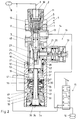
- the known level control valve 1 without height limitation is shown in the upper part of Figure 1. It has a housing 2 in which a valve tappet 3 which is hollow for ventilation purposes is guided in a sealing and sliding manner.
- a double valve body 4 is resiliently suspended in the housing 2 following a storage chamber 5.
- the double valve body 4 forms an inlet valve 4, 6 with a retracted edge 6 of the housing 2 and a first outlet valve 4, 7 with the upper edge 7 of the hollow valve tappet 3.
- Compressed air from a reservoir 8 is via a line 9 to a connection 10 on the housing 2 of the level control valve 1 and is applied via a check valve 11 in the storage chamber 5.
- the double valve body 4 and the check valve 11 can be supported on a common spring 12.
- a line 14 is connected to a connection 13 and leads to an air bellows 16 via a change-over charging valve 15.
- the connection 13 has a thickening 17 on the valve tappet 3, a connection to the inlet valve 4, 6 and the outlet valve 4, 7. Only one connection 13 and a line 14 to an air bellows 16 are shown here. It goes without saying that several lines can also be connected and provided here.
- An adjustment drive 18 for the movement of the valve tappet 3 and thus the actuation of the inlet valve 4, 6 or the outlet valve 4, 7 has an actuating rod 19 which engages a shaft 20 which carries an eccentric cam 21.
- the eccentric cam 21 slides in a guide groove 22 of a guide piece 23, which is translationally movable in the housing 2 coaxially with the valve tappet 3.
- the valve tappet 3 is adjustable in the guide piece 23 with the aid of a thread and, after the end position of the inlet valve 4, 6 and the outlet valve 4, 7 has been properly set, is locked with a nut 24.
- the setting of the valve tappet 3 in the guide piece 23 can also be done in a different way.
- this level control valve 1 The function of this level control valve 1 and its normal actuation of the intake valve 4, 6 and the exhaust valve 4, 7 are known.
- a vent housing 27 is attached to a ventilation opening 25 of the housing 2 of the level control valve 1, which is normally covered with a ventilation cap 26, which can be connected in a snap-in manner to the housing 2 of the level control valve via a snap connection 28. The position can also be secured by stud screws 29.
- a height limiter 30 is accommodated in the extension housing 27 and can be actuated via a valve rod 31.
- the valve rod 31 is sealingly guided through a sealed partition 32.
- the partition 32 is fixed in position in the attachment housing 27 by the snap connection to the housing 2 in its relative position.
- a double valve body 33 which is supported on a closing spring 34, can be sealingly displaced on the valve rod 31.
- the valve rod 31 carries an outlet seat 35 which, together with the double valve body 33, forms a second outlet valve 33, 35 - in addition to the first outlet valve 4, 7.
- the valve rod 31 is hollow and, in relation to the second outlet valve 33, 35, has one or more bores which axially penetrate the valve rod 31 Channel 37.
- the channel 37 has a connection to a ventilation opening 38, which is covered with the ventilation cap 26.
- the hollow valve rod 31 is not only sealingly guided in the partition wall 32, but also in the region of a seal 39.
- An insert 40 is sealingly accommodated in the extension housing 27, which carries a passage seat 41 which, together with the hollow double valve body 33, forms the check valve 33, 41, which represents the height limitation 30.
- the insert 40 is axially adjustable in a thread 42 in the neck housing 27 by turning, whereby the relative position of the passage seat 41 to the double valve body 33 is adjustable.
- the valve rod 31 is supported on the insert 40 via a spring 43.
- the valve rod 31 is provided with a stop 44 to which a counter-stop formed on the partition 32 is assigned.
- the force of the closing spring 34 is relatively weak.
- the spring 43 holds the valve rod 31 in its upper position, ie with its stop 44 in contact with the partition 32. If the stop 44 is missing, the force of the springs 34 and 43 must be adjusted accordingly.
- a rest position of the parts with respect to one another is shown here, in which the upper end 45 has a clearance 46 to the lower end of the nut 24 or the guide piece 23 or the valve tappet 3, that is to say a distance at which normal movements of the adjustment drive 18 take place. in which only the inlet valve 4, 6 and the outlet valve 4, 7 are actuated.
- the double valve body 33 is removed from the passage seat 41 by a stroke 47. It can be seen that the check valve 33, 41 only closes when the adjustment drive has performed a movement in which both the clearance 46 and the stroke 47 have been used up. Only then does the check valve 33, 41 come into its closed position. By turning the insert 40 in the extension housing 27, the stroke 47 can be changed while the clearance 46 remains constant.
- the limit stroke can thus be set and determined, when the stop valve 33, 41 closes.
- a supply line 48 to a connection 49 on the attachment housing 27 and from there into a storage chamber 50, which is closed only when the shut-off valve 33, 41 is closed. Otherwise there is a connection to a connection chamber 51 and through an opening 52 in the insert 40 to a connection 53, from which the supply line of the shuttle valve 15 with supply air continues in a line 54.
- the line 54 is closed on the shuttle valve 15, and the bellows 16 is controlled via the line 14. Only in the "lifting" position of the exchangeable charging valve 15 does supply air pass through the supply line 48 and the line 54 into the air bellows 16 until the height limitation begins by closing the check valve 33, 41.
- the particular advantage of the height limiter 30 in the extension housing 27 can be seen in the fact that a normally designed level control valve 1, as shown in the upper area of FIG. 1, can be easily and quickly inserted into a level control valve by removing the ventilation cap 26 and attaching the extension housing 27 can be converted with a height limiter 30, the corresponding line connections to the storage container 8 and to the shuttle valve 15 having to be attached.
- the air bellows 16 will raise the chassis, it being possible for the height limit 30 to be exceeded by closing the check valve 33, 41. As a result, the second outlet valve 33, 35 opens. The supply line 48 is closed and there is a targeted ventilation of the air bellows 16 via the opened second outlet valve 33, 35.
- the embodiment of the level control valve shown in FIG. 2 is constructed similarly to the embodiment according to FIG. 1, which is why a new description can be dispensed with in this regard.
- the height limiter 30, the check valve 33, 41 are designed and arranged somewhat differently.
- the passage seat 41 is here part of the hollow valve rod 31, while the outlet seat 35 is arranged on the insert 40.
- a stop 55 arranged on the valve rod 31 cooperates here with the insert 40.
- the valve rod 31 is hollow only for venting the first exhaust valve 4, 7. If the housing 2 can have its own ventilation opening, the valve rod 31 can also be designed without the channel 37, ie closed. Instead, a separate vent opening 56 for the second outlet valve 33, 35 is provided in the extension housing 27.
- cross bolts 57 can be provided to secure the shoulder housing 27 on the housing 2 of the level control valve 1 beyond the snap connection 28.
- the embodiment of the level control valve 1 according to FIG. 2 has the advantage that when the insert 40 is adjusted in the extension housing 27, the stroke 47 remains constant and only the clearance 46 is adjusted.
- the flow area of the check valve 33, 41 in the open state thus remains constant.
Landscapes
- Engineering & Computer Science (AREA)
- Mechanical Engineering (AREA)
- Lift Valve (AREA)
- Vehicle Body Suspensions (AREA)
Applications Claiming Priority (2)
| Application Number | Priority Date | Filing Date | Title |
|---|---|---|---|
| DE4416280 | 1994-05-07 | ||
| DE4416280A DE4416280C1 (de) | 1994-05-07 | 1994-05-07 | Niveauregelventil zum selbsttätigen Konstanthalten der Fahrzeughöhe eines Nutzfahrzeuges mit Luftfederung |
Publications (3)
| Publication Number | Publication Date |
|---|---|
| EP0680838A2 true EP0680838A2 (fr) | 1995-11-08 |
| EP0680838A3 EP0680838A3 (fr) | 1996-12-27 |
| EP0680838B1 EP0680838B1 (fr) | 1999-08-11 |
Family
ID=6517644
Family Applications (1)
| Application Number | Title | Priority Date | Filing Date |
|---|---|---|---|
| EP95106612A Expired - Lifetime EP0680838B1 (fr) | 1994-05-07 | 1995-05-03 | Soupape de régulation de niveau pour maintenir constante automatiquement la hauteur d'un véhicule utilitaire à suspension pneumatique |
Country Status (3)
| Country | Link |
|---|---|
| EP (1) | EP0680838B1 (fr) |
| DE (2) | DE4416280C1 (fr) |
| ES (1) | ES2135622T3 (fr) |
Cited By (1)
| Publication number | Priority date | Publication date | Assignee | Title |
|---|---|---|---|---|
| ES2133069A1 (es) * | 1996-07-31 | 1999-08-16 | Accesorios Y Elevadores Valenc | Mecanismo de regulacion de la presion de elevacion para valvulas de elevacion de ruedas de vehiculos con suspension neumatica. |
Families Citing this family (10)
| Publication number | Priority date | Publication date | Assignee | Title |
|---|---|---|---|---|
| DE19636002C1 (de) * | 1996-09-05 | 1997-10-16 | Grau Gmbh | Niveauregelventil zum selbsttätigen Konstanthalten der Fahrzeughöhe eines Nutzfahrzeuges mit Luftfederung |
| DE19923456C5 (de) * | 1999-05-21 | 2008-07-24 | Knorr-Bremse Systeme für Nutzfahrzeuge GmbH | Niveauregelventil für die Luftfederung von Fahrzeugen, insbesondere Nutzfahrzeugen |
| DE102009005229C5 (de) | 2009-01-20 | 2019-09-12 | Haldex Brake Products Aktiebolag | Luftfederanlage mit Höhenbegrenzung |
| CN101660548B (zh) * | 2009-09-25 | 2012-02-01 | 中国北方车辆研究所 | 液压锁止阀 |
| CN101670762B (zh) * | 2009-09-25 | 2011-04-20 | 中国北方车辆研究所 | 高度调节阀 |
| DE102009045732B4 (de) * | 2009-10-15 | 2012-11-29 | Haldex Brake Products Gmbh | Ventil für eine Druckluftanlage eines Nutzfahrzeugs |
| DE102009045734B4 (de) | 2009-10-15 | 2012-11-29 | Haldex Brake Products Gmbh | Ventil für eine Druckluftanlage eines Nutzfahrzeugs |
| DE102012014349B4 (de) * | 2012-07-19 | 2020-12-31 | Wabco Gmbh | Luftfederventil |
| EP3208119A1 (fr) | 2016-02-18 | 2017-08-23 | Haldex Brake Products Aktiebolag | Dispositif de vanne de controle de niveau actionne mecaniquement |
| EP4010212A1 (fr) | 2019-10-25 | 2022-06-15 | Iljin Motion & Control GmbH | Unité de réglage de hauteur de véhicule électromécanique et procédé de réglage de hauteur de véhicule |
Family Cites Families (3)
| Publication number | Priority date | Publication date | Assignee | Title |
|---|---|---|---|---|
| DE3446810C1 (de) * | 1984-12-21 | 1986-06-12 | Graubremse Gmbh, 6900 Heidelberg | Niveauregelventil mit Hoehenbegrenzung |
| DE3716436A1 (de) * | 1987-05-16 | 1988-12-01 | Graubremse Gmbh | Niveauregelventil mit hoehenbegrenzung |
| DE4012251C1 (fr) * | 1990-04-14 | 1991-07-11 | Grau Gmbh, 6900 Heidelberg, De |
-
1994
- 1994-05-07 DE DE4416280A patent/DE4416280C1/de not_active Expired - Fee Related
-
1995
- 1995-05-03 DE DE59506563T patent/DE59506563D1/de not_active Expired - Lifetime
- 1995-05-03 ES ES95106612T patent/ES2135622T3/es not_active Expired - Lifetime
- 1995-05-03 EP EP95106612A patent/EP0680838B1/fr not_active Expired - Lifetime
Cited By (1)
| Publication number | Priority date | Publication date | Assignee | Title |
|---|---|---|---|---|
| ES2133069A1 (es) * | 1996-07-31 | 1999-08-16 | Accesorios Y Elevadores Valenc | Mecanismo de regulacion de la presion de elevacion para valvulas de elevacion de ruedas de vehiculos con suspension neumatica. |
Also Published As
| Publication number | Publication date |
|---|---|
| DE4416280C1 (de) | 1995-05-11 |
| EP0680838B1 (fr) | 1999-08-11 |
| DE59506563D1 (de) | 1999-09-16 |
| ES2135622T3 (es) | 1999-11-01 |
| EP0680838A3 (fr) | 1996-12-27 |
Similar Documents
| Publication | Publication Date | Title |
|---|---|---|
| DE4409252C2 (de) | Luftfederungsanlage | |
| DE3301544C2 (fr) | ||
| EP0681128A1 (fr) | Electrovanne | |
| EP0258812B1 (fr) | Dispositif de réglage et blocage continu | |
| DE10232554B4 (de) | Magnetventil für Nutzfahrzeuge mit Luftfederung | |
| DE3900927A1 (de) | Pneumatisches oder hydropneumatisches verstellelement | |
| DE4416280C1 (de) | Niveauregelventil zum selbsttätigen Konstanthalten der Fahrzeughöhe eines Nutzfahrzeuges mit Luftfederung | |
| DE3008002A1 (de) | Verschlussdeckel insbesondere fuer einen kraftfahrzeugkuehler | |
| DE3446810C1 (de) | Niveauregelventil mit Hoehenbegrenzung | |
| DE10003045A1 (de) | Luftfederungsanlage | |
| DE3722306C2 (fr) | ||
| DE2925885C2 (fr) | ||
| DE3922566C2 (fr) | ||
| EP0733749A1 (fr) | Dispositif d'actionnement pour un orifice de vidange d'un réservoir de chasse d'eau | |
| DE19636946C1 (de) | Baueinheit zum Steuern einer Liftachse an einem mehrachsigen Nutzfahrzeug | |
| DE3929934C2 (fr) | ||
| EP0594998B1 (fr) | Valve relais en particulier valve de contrôle ou commande pour remorques pour systèmes pneumatiques de freinage de véhicules | |
| DE8702724U1 (de) | Türbeschlag | |
| DE2920507C2 (de) | Niveauregelventil zum selbständigen Konstanthalten der Fahrgestellhöhe eines Fahrzeuges mit Luftfederung | |
| DE4219435A1 (de) | Einrichtung zum Abschalten eines von einem Tassenstößel betätigten Ventils einer Brennkraftmaschine | |
| EP2317190B1 (fr) | Adaptateur pour vannes à tailles différentes | |
| DE19636002C1 (de) | Niveauregelventil zum selbsttätigen Konstanthalten der Fahrzeughöhe eines Nutzfahrzeuges mit Luftfederung | |
| DE102019218402B4 (de) | Federdom für ein Hydraulikventil und Hydraulikventil mit einem solchen Federdom | |
| EP0124726A1 (fr) | Valve de commande pour remorques | |
| DE1555636C (de) | Hohenregelventil für luftgefederte Fahrzeuge |
Legal Events
| Date | Code | Title | Description |
|---|---|---|---|
| PUAI | Public reference made under article 153(3) epc to a published international application that has entered the european phase |
Free format text: ORIGINAL CODE: 0009012 |
|
| AK | Designated contracting states |
Kind code of ref document: A2 Designated state(s): DE ES FR GB IT |
|
| PUAL | Search report despatched |
Free format text: ORIGINAL CODE: 0009013 |
|
| AK | Designated contracting states |
Kind code of ref document: A3 Designated state(s): DE ES FR GB IT |
|
| 17P | Request for examination filed |
Effective date: 19970207 |
|
| 17Q | First examination report despatched |
Effective date: 19980305 |
|
| GRAG | Despatch of communication of intention to grant |
Free format text: ORIGINAL CODE: EPIDOS AGRA |
|
| RAP1 | Party data changed (applicant data changed or rights of an application transferred) |
Owner name: HALDEX BRAKE PRODUCTS GMBH & CO. KG |
|
| GRAG | Despatch of communication of intention to grant |
Free format text: ORIGINAL CODE: EPIDOS AGRA |
|
| GRAG | Despatch of communication of intention to grant |
Free format text: ORIGINAL CODE: EPIDOS AGRA |
|
| GRAH | Despatch of communication of intention to grant a patent |
Free format text: ORIGINAL CODE: EPIDOS IGRA |
|
| GRAH | Despatch of communication of intention to grant a patent |
Free format text: ORIGINAL CODE: EPIDOS IGRA |
|
| ITF | It: translation for a ep patent filed | ||
| GRAA | (expected) grant |
Free format text: ORIGINAL CODE: 0009210 |
|
| AK | Designated contracting states |
Kind code of ref document: B1 Designated state(s): DE ES FR GB IT |
|
| GBT | Gb: translation of ep patent filed (gb section 77(6)(a)/1977) |
Effective date: 19990812 |
|
| REF | Corresponds to: |
Ref document number: 59506563 Country of ref document: DE Date of ref document: 19990916 |
|
| ET | Fr: translation filed | ||
| REG | Reference to a national code |
Ref country code: ES Ref legal event code: FG2A Ref document number: 2135622 Country of ref document: ES Kind code of ref document: T3 |
|
| PLBE | No opposition filed within time limit |
Free format text: ORIGINAL CODE: 0009261 |
|
| STAA | Information on the status of an ep patent application or granted ep patent |
Free format text: STATUS: NO OPPOSITION FILED WITHIN TIME LIMIT |
|
| 26N | No opposition filed | ||
| REG | Reference to a national code |
Ref country code: GB Ref legal event code: IF02 |
|
| REG | Reference to a national code |
Ref country code: FR Ref legal event code: TP |
|
| REG | Reference to a national code |
Ref country code: FR Ref legal event code: TP |
|
| REG | Reference to a national code |
Ref country code: ES Ref legal event code: PC2A |
|
| REG | Reference to a national code |
Ref country code: GB Ref legal event code: 732E |
|
| PGFP | Annual fee paid to national office [announced via postgrant information from national office to epo] |
Ref country code: GB Payment date: 20100324 Year of fee payment: 16 |
|
| PGFP | Annual fee paid to national office [announced via postgrant information from national office to epo] |
Ref country code: FR Payment date: 20100608 Year of fee payment: 16 Ref country code: ES Payment date: 20100520 Year of fee payment: 16 |
|
| PGFP | Annual fee paid to national office [announced via postgrant information from national office to epo] |
Ref country code: IT Payment date: 20100527 Year of fee payment: 16 Ref country code: DE Payment date: 20100420 Year of fee payment: 16 |
|
| REG | Reference to a national code |
Ref country code: DE Ref legal event code: R119 Ref document number: 59506563 Country of ref document: DE |
|
| REG | Reference to a national code |
Ref country code: DE Ref legal event code: R119 Ref document number: 59506563 Country of ref document: DE |
|
| GBPC | Gb: european patent ceased through non-payment of renewal fee |
Effective date: 20110503 |
|
| REG | Reference to a national code |
Ref country code: FR Ref legal event code: ST Effective date: 20120131 |
|
| PG25 | Lapsed in a contracting state [announced via postgrant information from national office to epo] |
Ref country code: IT Free format text: LAPSE BECAUSE OF NON-PAYMENT OF DUE FEES Effective date: 20110503 |
|
| PG25 | Lapsed in a contracting state [announced via postgrant information from national office to epo] |
Ref country code: FR Free format text: LAPSE BECAUSE OF NON-PAYMENT OF DUE FEES Effective date: 20110531 |
|
| PG25 | Lapsed in a contracting state [announced via postgrant information from national office to epo] |
Ref country code: GB Free format text: LAPSE BECAUSE OF NON-PAYMENT OF DUE FEES Effective date: 20110503 |
|
| REG | Reference to a national code |
Ref country code: ES Ref legal event code: FD2A Effective date: 20130531 |
|
| PG25 | Lapsed in a contracting state [announced via postgrant information from national office to epo] |
Ref country code: DE Free format text: LAPSE BECAUSE OF NON-PAYMENT OF DUE FEES Effective date: 20111130 |
|
| PG25 | Lapsed in a contracting state [announced via postgrant information from national office to epo] |
Ref country code: ES Free format text: LAPSE BECAUSE OF NON-PAYMENT OF DUE FEES Effective date: 20110504 |