EP0680847B2 - Drehbares elektrisches Verbindungselement - Google Patents
Drehbares elektrisches Verbindungselement Download PDFInfo
- Publication number
- EP0680847B2 EP0680847B2 EP95401004A EP95401004A EP0680847B2 EP 0680847 B2 EP0680847 B2 EP 0680847B2 EP 95401004 A EP95401004 A EP 95401004A EP 95401004 A EP95401004 A EP 95401004A EP 0680847 B2 EP0680847 B2 EP 0680847B2
- Authority
- EP
- European Patent Office
- Prior art keywords
- contactor
- tab
- contactor according
- tabs
- elements
- Prior art date
- Legal status (The legal status is an assumption and is not a legal conclusion. Google has not performed a legal analysis and makes no representation as to the accuracy of the status listed.)
- Expired - Lifetime
Links
- 239000004020 conductor Substances 0.000 claims description 8
- 238000006073 displacement reaction Methods 0.000 claims description 4
- 210000002105 tongue Anatomy 0.000 description 11
- 238000009434 installation Methods 0.000 description 3
- 239000000463 material Substances 0.000 description 2
- 238000000465 moulding Methods 0.000 description 2
- 210000000056 organ Anatomy 0.000 description 2
- 230000000295 complement effect Effects 0.000 description 1
- 238000010586 diagram Methods 0.000 description 1
- 229920002457 flexible plastic Polymers 0.000 description 1
- 238000012423 maintenance Methods 0.000 description 1
- 238000000034 method Methods 0.000 description 1
- 230000002093 peripheral effect Effects 0.000 description 1
- 229920003023 plastic Polymers 0.000 description 1
- 239000004033 plastic Substances 0.000 description 1
- 239000002985 plastic film Substances 0.000 description 1
- 230000001681 protective effect Effects 0.000 description 1
- 230000000717 retained effect Effects 0.000 description 1
- 230000008054 signal transmission Effects 0.000 description 1
Images


Classifications
-
- B—PERFORMING OPERATIONS; TRANSPORTING
- B60—VEHICLES IN GENERAL
- B60R—VEHICLES, VEHICLE FITTINGS, OR VEHICLE PARTS, NOT OTHERWISE PROVIDED FOR
- B60R16/00—Electric or fluid circuits specially adapted for vehicles and not otherwise provided for; Arrangement of elements of electric or fluid circuits specially adapted for vehicles and not otherwise provided for
- B60R16/02—Electric or fluid circuits specially adapted for vehicles and not otherwise provided for; Arrangement of elements of electric or fluid circuits specially adapted for vehicles and not otherwise provided for electric constitutive elements
- B60R16/023—Electric or fluid circuits specially adapted for vehicles and not otherwise provided for; Arrangement of elements of electric or fluid circuits specially adapted for vehicles and not otherwise provided for electric constitutive elements for transmission of signals between vehicle parts or subsystems
- B60R16/027—Electric or fluid circuits specially adapted for vehicles and not otherwise provided for; Arrangement of elements of electric or fluid circuits specially adapted for vehicles and not otherwise provided for electric constitutive elements for transmission of signals between vehicle parts or subsystems between relatively movable parts of the vehicle, e.g. between steering wheel and column
Definitions
- the present invention relates to the field of rotary electrical contactors.
- the present invention finds in particular, but not exclusively, application to signal transmission electric between means linked to the steering wheel of a vehicle automobile, for example an inflation system airbag type protective bag and control means independent of the steering wheel linked to the column direction.
- Document DE-A-4233499 describes an electrical contactor turning comprising two elements susceptible of relative rotation and a flexible conductor placed between these two elements, as well as means to immobilize the two front contactor elements with relative rotation mounting.
- the temporary locking between the two elements of the contactor is obtained thanks to a possibility of relative axial displacement between these two elements between a position of locking in which the two elements are engaged by teeth peripherals and a working position in which after axial shift, the two elements are capable of relative displacement in rotation.
- one of the elements carries two bars fitted with elastic tabs engaging the support complementary, for example the steering wheel to retain this element.
- the present invention now aims to improve known rotary electrical contactors.
- An object of the present invention is in particular to propose a new rotary electrical contactor which to facilitate the assembly process.
- said tabs are adapted to remove the play between the element which carries them and the associated body which receives it on the site of use, for example the steering wheel of the motor vehicle.
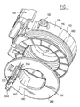
- the rotary electrical contactor shown in the appended figures essentially comprises, a fixed housing 100, a rotary cover 200 and a conductor flexible electric 300.
- the fixed box 100 can be the subject of many embodiments.
- the fixed housing 100 is made by molding in material plastic.
- the housing 100 essentially comprises two concentric circular walls 110, 112 interconnected by a wall of base 114 in the shape of a crown.
- the walls 110, 112 and 114 mentioned above thus delimit an annular chamber 116 able to contain the conductor 200.
- the external cylindrical wall 110 is provided with preferably 120 attachment points formed for example eyelets as shown in the figures attached.
- outer cylindrical wall 110 is preferably provided on its outer periphery with a connector body 130.
- the connector body 130 includes contacts electrical 131 designed to be connected respectively to tracks of flexible conductor 300 or else is adapted to receive one end of this conductor flexible 300.
- the connector body 130 advantageously extends axially, i.e. in a general direction parallel to the axis of the walls 110, 112.
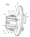
- the cover 200 can also be the subject of many embodiments. According to the embodiment particular shown in the appended figures, and not limiting, the cover 200 essentially comprises a flat base wall 210 in the shape of a crown, coaxial with the housing 100.
- the wall 210 is provided on its internal periphery of a cylindrical barrel 220 or different cylindrical segments evenly distributed around its axis, as shown in the attached figures. This was 220 or the sectors composing it are engaged in the internal space of the housing 100. Thus, the cover 200 is mounted and guided in rotation on the housing 100.
- the cover 200 is retained in translation on the housing 100 by any suitable means, for example using teeth 222 projecting from the end of the barrel 220 or component segments cephilt 220, which teeth 222 engage the internal cylindrical wall 112 of the case.
- the cover 210 is also provided a connector body 230, advantageously at its internal periphery, on its opposite face at barrel 220.
- the connector body 230 extends in an axial direction, i.e. parallel to the axis cover 200 and housing 100.
- This connector body 230 is also provided electrically conductive contacts suitable for come in connection with respective tracks of the driver flexible 300, or the connector body 230 is adapted to receive the second end of this conductor 300.
- the pivoting cover 200 is connected by any suitable means, rotating, with the steering wheel of the vehicle automobile, while the housing 100 is fixed on a fixed part of the vehicle, for example the column of direction.
- the flexible conductor 300 can also the object of many embodiments. It could be for example a bundle of electrically conductive wires isolated, or preferably from a circuit printed or flexible plastic film provided with several parallel metallic tracks.
- At least one of these elements 100, 200 includes at least one elastic tongue 240 adapted to be requested to move when placing the contactor on its site of use.
- two tabs are provided elastic 240 on the connector body 230 of the cover swivel 200.
- the body of connector 230 includes a molded block with the cover 200 on the inner periphery of the base wall in crown 210 composing the latter.
- This block forming the connector body 230 has a symmetry with respect to an axial plane, i.e. a plane passing through the axis of the cover 200.
- This block thus has the general shape of a blade arranged tangentially relative to the internal periphery of the crown 210.
- the two tabs 240 came from molding respectively on the sides of the connector body 230.
- Tabs 240 extend in one direction general axial, i.e. substantially parallel to the axis of the cover 200.
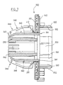
- each tab 240 can be the subject of numerous embodiments. According to the embodiment particular and nonlimiting shown in the figures attached, each tab 240 has a section rectangular, preferably square. It connects on the top of the connector body 230 opposite the base wall 210 via a hinge zone coming from material 242 of small width.
- tongues 240 have a length greater than that of connector body 230.
- the tongues 240 pass through, free to move, the base plate 210 of the cover 200, at level of lights 212 formed therein.
- tabs 240 extend beyond the base plate 210, towards housing 100, as shown see for example in FIG. 2.
- the free ends of the tongues 240 which emerge by relative to the base wall 210 are referenced 241.
- tongues 240 are preferably each provided on their side face opposite the plane of symmetry of the connector body 230 of a ramp solicitation 244.
- This loading ramp 244 preferably diverges with respect to the plane of symmetry of the connector body 230 by approaching the base plate 210.
- these ramps 244 are adapted to be requested by the steering wheel during the installation of the contactor.
- annular structure V shown diagrammatically in FIGS. 8 to 11, whose internal radius is between the radius minimum and maximum radius, relative to the axis of the cover 200, of the aforementioned ramps 244.
- annular structure V in the form of a cross section rectangular. This structure can however the subject of many variations.
- these ramps 244 are formed of ribs 246 molded on the sides of the tabs 240.
- the housing 100 is provided with notches 142 able to receive at rest the ends 142 of the tongues 140.
- the notches 142 are suitable for prohibit at rest any relative rotation between the cover 200 and the housing 100.
- the notches 142 can be formed on the above-mentioned assembly consisting of walls 110, 112 and 114 or on any sub-assembly linked to this box 100, for example on a crown 140 linked to this case 100 to at least partially close the opening contour of room 116.
- notches 142 on the inner periphery of the crown 140. These notches 142 have symmetry by relative to an axial plane of the crown 140.
- each notch 142 is thus formed of two planar surfaces 143, 144 orthogonal to each other: a first surface 143 perpendicular to the above-mentioned plane of symmetry and a second surface 144 parallel to this plane of symmetry and directed to it.
- the two surfaces 143 and 144 open into the internal channel of the crown 140.
- the ends 241 tabs 240 are placed in the notches 142.
- the tabs 240 are recalled elastically at rest towards the surfaces 144 by the articulation zones 242. The cooperation thus defined between the tongues 240 and the notches 142 therefore prohibited any rotation between the cover 200 and the housing 100.
- this locked assembly is operated in the middle position of the contactor, i.e. in the median of the relative travel allowed between the cover 200 and the box 100. This arrangement allows guarantee the operation of the contactor thereafter.
- the contactor thus assembled is fixed on the top of the steering column, by its case 100 is the 120 anchor points.
- the structure annular V thereof comes to stress ramps 244. Consequently the tongues 240 are deformed resiliently in approximation so that the tabs escape the notches 142.
- the cover 200 is then made free to pivot relative to the housing 100.
- tabs 244 thus elastically deformed and stressed by the structure ring V allow to remove any play between the steering wheel V and cover 200 and therefore reduce the operating noise of the contactor.
- the structure of the ramps 244 is adapted to allow loading of the tabs 240 by structure V, and therefore an unlocking of these tabs 240, in a wide positioning range axial of the steering wheel.
- the steering wheel is shown schematically in its nominal position while it is shown in the minimum position in FIG. 9 and in maximum position in figure 11.
- tabs 240 on the housing 100 and not on the cover 200, or even both on the housing 100 and on cover 200, or even provide anti-backlash tabs 240 on the box 100 to remove the play between the case 100 and the member receiving it, for example the top of the steering column, even provide 240 anti-play tabs both on the housing 100 and on the cover 200, so that these tabs 240 remove the clearance between the housing 100, the cover 200 and respectively the organs receiving these, either by example the top of the steering column for the box 100 and the handwheel for cover 200 or vice versa.
- the contactor according to the present invention allows not only to remove the operating clearance between the elements of the contactor and the organs which receive these but also allows to lock the contactor advantageously in a preset position in a midpoint position, as soon as it is assembled and until the steering wheel is assembled on the vehicle.
- unlocking is ensured by mounting steering wheel on the vehicle without intervention manual or other.
- tongues 240 can be stressed to the housing 100 by added spring means independent of hinge areas 242.
Landscapes
- Engineering & Computer Science (AREA)
- Mechanical Engineering (AREA)
- Steering Controls (AREA)
- Mechanisms For Operating Contacts (AREA)
- Measuring Leads Or Probes (AREA)
- Rotary Switch, Piano Key Switch, And Lever Switch (AREA)
- Coupling Device And Connection With Printed Circuit (AREA)
Claims (18)
- Drehbarer elektrischer Verbinder mit zwei Elementen (100, 200), die Relativbewegungen ausführen können, und einem biegsamen Leiter (300), angebracht zwischen diesen beiden Elementen (100, 200), wobei wenigstens das eine (200) dieser Elemente (100, 200) zwei elastische Spreizeinrichtungen (240) umfasst, die so angepasst sind, dass sie beim Anbringen des Verbinders an seinem Einsatzort einer Verschiebebelastung ausgesetzt sind,
dadurch gekennzeichnet, dass die beiden Spreizeinrichtungen (240) jeweils angegossen sind auf den Flanken eines elektrischen Verbindungskörpers (230), gebildet aus einem Gussblock mit dem Element (200), das ihn trägt, wobei der Verbindungskörper (230) eine Symmetrie in Bezug auf eine axiale Ebene aufweist und die elastischen Spreizeinrichtungen (240) bezüglich dieser axialen Ebene symmetrisch sind und in Ruhestellung elastisch rückgestellt werden gegen das andere Element (100) und dabei angepasst sind, bei Entfernung von diesem anderen Element (100) beim Anbringen des Verbinders an seinem Einsatzort belastet zu werden, so dass die Spreizeinrichtungen (240) in Ruhestellung die beiden Elemente (100, 200) in einer bestimmten Zusammenbaustellung verriegeln, während die Spreizeinrichtungen (240) diese beiden Elemente (100, 200) beim Anbringen des Verbinders automatisch freigeben. - Verbinder nach Anspruch 1, dadurch gekennzeichnet, dass die genannten Spreizeinrichtungen (240) angepasst sind, das Spiel zu beseitigen zwischen dem Element (200), das sie trägt, und dem zugeordneten Organ (V), das dieses aufnimmt am Einsatzort, z.B. dem Steuerrad des Kraftfahrzeugs.
- Verbinder nach einem der Ansprüche 1 oder 2, dadurch gekennzeichnet, dass jede Spreizeinrichtung (240) sich in einer axialen Hauptrichtung erstreckt.
- Verbinder nach einem der Ansprüche 1 bis 3, dadurch gekennzeichnet, dass jede Spreizeinrichtung (240) mit dem Verbindungskörper (230) an dessen Spitze durch eine mitangegossene Gelenkzone (242) von geringer Breite verbunden ist.
- Verbinder nach Anspruch 4, dadurch gekennzeichnet, dass jede Spreizeinrichtung (240) eine größere Länge als der Verbindungskörper (230) aufweist.
- Verbinder nach einem der Ansprüche 1 bis 5, dadurch gekennzeichnet, dass jede Spreizeinrichtung (240) bewegungs- bzw. verschiebungsfrei eine Grundplatte (210) des sie tragenden Elements (200) durchquert, in Höhe eines Schlitz- bzw. Langlochs (212).
- Verbinder nach Anspruch 6, dadurch gekennzeichnet, dass jede Spreizeinrichtung (240) sich über die Grundplatte (210) hinaus erstreckt.
- Verbinder nach Anspruch 1 bis 7, dadurch gekennzeichnet, dass jede Spreizeinrichtung (240) mit einer Belastungsrampe (244) versehen ist.
- Verbinder nach Anspruch 8, dadurch gekennzeichnet, dass die Belastungsrampen (244) in Richtung Grundplatte (210) in Bezug auf die Symmetrieebene divergieren.
- Verbinder nach Anspruch 1 bis 9, dadurch gekennzeichnet, dass das andere Element (100) mit wenigstens einer Kerbe (142) versehen ist, die in Ruhestellung das Ende (241) der Spreizeinrichtung (240) aufnimmt.
- Verbinder nach Anspruch 10, dadurch gekennzeichnet, dass das andere Element (100) zwei Kerben (142) umfasst, symmetrisch in Bezug auf eine axiale Ebene.
- Verbinder nach einem der Ansprüche 10 oder 11, dadurch gekennzeichnet, dass jede Kerbe (142) gebildet wird durch zwei zueinander rechtwinklige ebene Flächen (143, 144): eine erste Fläche (143), senkrecht zur genannten Symmetrieebene, und eine zweite Fläche (144), parallel zu dieser Symmetrieebene und dieser zugewandt.
- Verbinder nach einem der Ansprüche 1 bis 12, dadurch gekennzeichnet, dass jede Spreizeinrichtung (240) angepasst ist, um den Verbinder in der Mittelstellung zu verriegeln.
- Verbinder nach einem der Ansprüche 1 bis 13, dadurch gekennzeichnet, dass die Spreizeinrichtungen (240) auf einem schwenk- bzw. drehbaren Deckel des Verbinders (200) vorgesehen sind.
- Verbinder nach einem der Ansprüche 1 bis 13, dadurch gekennzeichnet, dass die Spreizeinrichtungen (240) auf einem feststehenden Gehäuse (100) des Verbinders vorgesehen sind.
- Verbinder nach einem der Ansprüche 1 bis 15, dadurch gekennzeichnet, dass wenigstens eine Spreizeinrichtung (240) auf einem drehbaren Deckel (200) des Verbinders vorgesehen ist, und wenigstens eine Spreizeinrichtung (240) auf einem feststehenden Gehäuse (100) der Verbinders vorgesehen ist.
- Verbinder nach einem der Ansprüche 1 bis 16, dadurch gekennzeichnet, dass jede Spreizeinrichtung (240) durch unabhängige angebaute Federeinrichtungen belastet wird.
- Verbinder nach einem der Ansprüche 1 bis 17, dadurch gekennzeichnet, dass er angepasst ist, um eine Verschiebung jeder elastischen Spreizeinrichtung (240) und eine Entriegelung des Verbinders durch die Montage eines Kraftfahrzeugsteuerrads sicherzustellen, ohne manuelles oder anderes Eingreifen.
Applications Claiming Priority (2)
| Application Number | Priority Date | Filing Date | Title |
|---|---|---|---|
| FR9405461A FR2719714B1 (fr) | 1994-05-04 | 1994-05-04 | Contacteur électrique tournant perfectionné. |
| FR9405461 | 1994-05-04 |
Publications (3)
| Publication Number | Publication Date |
|---|---|
| EP0680847A1 EP0680847A1 (de) | 1995-11-08 |
| EP0680847B1 EP0680847B1 (de) | 1997-12-29 |
| EP0680847B2 true EP0680847B2 (de) | 2002-07-17 |
Family
ID=9462860
Family Applications (1)
| Application Number | Title | Priority Date | Filing Date |
|---|---|---|---|
| EP95401004A Expired - Lifetime EP0680847B2 (de) | 1994-05-04 | 1995-05-02 | Drehbares elektrisches Verbindungselement |
Country Status (4)
| Country | Link |
|---|---|
| EP (1) | EP0680847B2 (de) |
| DE (1) | DE69501283T3 (de) |
| ES (1) | ES2111373T5 (de) |
| FR (1) | FR2719714B1 (de) |
Citations (1)
| Publication number | Priority date | Publication date | Assignee | Title |
|---|---|---|---|---|
| DE4233499A1 (de) † | 1992-07-30 | 1994-04-07 | Kabelmetal Electro Gmbh | Vorrichtung zur Signalübertragung zwischen zwei Endstellen |
Family Cites Families (3)
| Publication number | Priority date | Publication date | Assignee | Title |
|---|---|---|---|---|
| DE3565195D1 (en) * | 1985-03-23 | 1988-10-27 | Petri Ag | Electrical contact device for a shock-preventing airbag-safety system for motor vehicles |
| US4797109A (en) * | 1988-02-25 | 1989-01-10 | Methode Electronics, Inc. | Coiled wire interconnector |
| DE4014485C2 (de) * | 1990-05-07 | 2002-02-07 | Eaton Controls Gmbh | Elektrische Verbindungseinrichtung |
-
1994
- 1994-05-04 FR FR9405461A patent/FR2719714B1/fr not_active Expired - Fee Related
-
1995
- 1995-05-02 EP EP95401004A patent/EP0680847B2/de not_active Expired - Lifetime
- 1995-05-02 DE DE1995601283 patent/DE69501283T3/de not_active Expired - Lifetime
- 1995-05-02 ES ES95401004T patent/ES2111373T5/es not_active Expired - Lifetime
Patent Citations (1)
| Publication number | Priority date | Publication date | Assignee | Title |
|---|---|---|---|---|
| DE4233499A1 (de) † | 1992-07-30 | 1994-04-07 | Kabelmetal Electro Gmbh | Vorrichtung zur Signalübertragung zwischen zwei Endstellen |
Also Published As
| Publication number | Publication date |
|---|---|
| ES2111373T3 (es) | 1998-03-01 |
| DE69501283T2 (de) | 1998-04-16 |
| FR2719714A1 (fr) | 1995-11-10 |
| EP0680847A1 (de) | 1995-11-08 |
| DE69501283T3 (de) | 2003-01-02 |
| FR2719714B1 (fr) | 1996-07-26 |
| ES2111373T5 (es) | 2002-12-16 |
| EP0680847B1 (de) | 1997-12-29 |
| DE69501283D1 (de) | 1998-02-05 |
Similar Documents
| Publication | Publication Date | Title |
|---|---|---|
| FR2549303A2 (fr) | Connecteur electrique | |
| EP0680847B2 (de) | Drehbares elektrisches Verbindungselement | |
| EP0704345B1 (de) | Elektrischer Drehschalter mit erleichterter Montage/Demontage | |
| FR2786624A1 (fr) | Rotor d'alternateur de vehicule a aimants permanents intercalaires | |
| EP0688032B1 (de) | Unter dem Lenkrad angebrachtes Schaltsystem für Kraftfahrzeuge | |
| EP0649774B1 (de) | Einrichtung zum Festsetzen einer Schraube zur Steuerung der Neigung eines Scheinwerferreflektors | |
| EP0296961B1 (de) | Befestigungsvorrichtung | |
| EP1108637B1 (de) | Einrichtung für den oberen Teil einer Kraftfahrzeuglenksäule | |
| FR2725313A1 (fr) | Contacteur electrique tournant perfectionne autorisant une pose/depose aisee | |
| FR3049016B1 (fr) | Dispositif de fixation d'un soufflet sur un pommeau de levier de commande de boite de vitesses. | |
| EP0457633B1 (de) | Einrichtung für Befestigung eines Schlosses in einem Türgriff, insbesondere der Griff einer Autotür | |
| EP0703371B1 (de) | Vorrichtung zur Befestigung einer Anordnung an einer Säule, insbesondere für die Befestigung einer elektrischen Schaltvorrichtung an einer Kraftfahrzeuglenksäule | |
| FR2690285A1 (fr) | Dispositif de connexion électrique entre deux pièces susceptibles de rotation relative. | |
| EP0566443A1 (de) | Befestigungsvorrichtung für ein Scheibenwischblatt auf einem Wischarm | |
| FR2770005A1 (fr) | Bouton de commande, notamment pour tableau de bord de vehicule automobile | |
| FR2715617A1 (fr) | Projecteur de véhicule, comportant des moyens perfectionnés de montage d'un correcteur de l'inclinaison du réflecteur. | |
| EP1607267B1 (de) | Schalthebel für elektrische Fahrzeugschalter | |
| FR2638128A1 (fr) | Capot de protection notamment pour projecteur de vehicule automobile | |
| FR2701160A1 (fr) | Commutateur électrique d'antivol de direction pour véhicule automobile. | |
| FR2731300A1 (fr) | Contacteur electrique tournant perfectionne a bruit de fonctionnement reduit | |
| FR2479753A1 (fr) | Dispositif de reglage de l'orientation d'un premier ensemble par rapport a un deuxieme ensemble, et notamment d'un projecteur par rapport a la carrosserie d'un vehicule | |
| EP2119601A1 (de) | System zur Montage in neutraler Ausgangsstellung eines Drehkontakts für den oberen Teil der Lenksäule eines Fahrzeugs | |
| FR2754573A1 (fr) | Dispositif d'assemblage reglable | |
| FR2749971A1 (fr) | Systeme de commande notamment commutateur electrique pour vehicules automobiles fixe sur un haut de colonne | |
| FR2746868A1 (fr) | Systeme de commande ou d'affichage pour vehicules automobiles comprenant des moyens de fixation perfectionnes |
Legal Events
| Date | Code | Title | Description |
|---|---|---|---|
| PUAI | Public reference made under article 153(3) epc to a published international application that has entered the european phase |
Free format text: ORIGINAL CODE: 0009012 |
|
| AK | Designated contracting states |
Kind code of ref document: A1 Designated state(s): DE ES GB IT |
|
| 17P | Request for examination filed |
Effective date: 19960415 |
|
| GRAG | Despatch of communication of intention to grant |
Free format text: ORIGINAL CODE: EPIDOS AGRA |
|
| 17Q | First examination report despatched |
Effective date: 19970313 |
|
| GRAG | Despatch of communication of intention to grant |
Free format text: ORIGINAL CODE: EPIDOS AGRA |
|
| GRAH | Despatch of communication of intention to grant a patent |
Free format text: ORIGINAL CODE: EPIDOS IGRA |
|
| GRAH | Despatch of communication of intention to grant a patent |
Free format text: ORIGINAL CODE: EPIDOS IGRA |
|
| GRAA | (expected) grant |
Free format text: ORIGINAL CODE: 0009210 |
|
| AK | Designated contracting states |
Kind code of ref document: B1 Designated state(s): DE ES GB IT |
|
| GBT | Gb: translation of ep patent filed (gb section 77(6)(a)/1977) |
Effective date: 19971229 |
|
| REF | Corresponds to: |
Ref document number: 69501283 Country of ref document: DE Date of ref document: 19980205 |
|
| REG | Reference to a national code |
Ref country code: ES Ref legal event code: FG2A Ref document number: 2111373 Country of ref document: ES Kind code of ref document: T3 |
|
| ITF | It: translation for a ep patent filed | ||
| PLBQ | Unpublished change to opponent data |
Free format text: ORIGINAL CODE: EPIDOS OPPO |
|
| PLBI | Opposition filed |
Free format text: ORIGINAL CODE: 0009260 |
|
| PLBF | Reply of patent proprietor to notice(s) of opposition |
Free format text: ORIGINAL CODE: EPIDOS OBSO |
|
| 26 | Opposition filed |
Opponent name: ALCATEL KABEL BETEILIGUNGS-AG Effective date: 19980928 |
|
| PLBF | Reply of patent proprietor to notice(s) of opposition |
Free format text: ORIGINAL CODE: EPIDOS OBSO |
|
| PLAW | Interlocutory decision in opposition |
Free format text: ORIGINAL CODE: EPIDOS IDOP |
|
| APAC | Appeal dossier modified |
Free format text: ORIGINAL CODE: EPIDOS NOAPO |
|
| APAE | Appeal reference modified |
Free format text: ORIGINAL CODE: EPIDOS REFNO |
|
| APAC | Appeal dossier modified |
Free format text: ORIGINAL CODE: EPIDOS NOAPO |
|
| PLBQ | Unpublished change to opponent data |
Free format text: ORIGINAL CODE: EPIDOS OPPO |
|
| PLAB | Opposition data, opponent's data or that of the opponent's representative modified |
Free format text: ORIGINAL CODE: 0009299OPPO |
|
| R26 | Opposition filed (corrected) |
Opponent name: ALCATEL KABEL BETEILIGUNGS-AG Effective date: 19980928 |
|
| APAC | Appeal dossier modified |
Free format text: ORIGINAL CODE: EPIDOS NOAPO |
|
| REG | Reference to a national code |
Ref country code: GB Ref legal event code: IF02 |
|
| PLAW | Interlocutory decision in opposition |
Free format text: ORIGINAL CODE: EPIDOS IDOP |
|
| PUAH | Patent maintained in amended form |
Free format text: ORIGINAL CODE: 0009272 |
|
| STAA | Information on the status of an ep patent application or granted ep patent |
Free format text: STATUS: PATENT MAINTAINED AS AMENDED |
|
| 27A | Patent maintained in amended form |
Effective date: 20020717 |
|
| AK | Designated contracting states |
Kind code of ref document: B2 Designated state(s): DE ES GB IT |
|
| GBTA | Gb: translation of amended ep patent filed (gb section 77(6)(b)/1977) | ||
| REG | Reference to a national code |
Ref country code: ES Ref legal event code: DC2A Date of ref document: 20020904 Kind code of ref document: T5 |
|
| APAH | Appeal reference modified |
Free format text: ORIGINAL CODE: EPIDOSCREFNO |
|
| PGFP | Annual fee paid to national office [announced via postgrant information from national office to epo] |
Ref country code: DE Payment date: 20120514 Year of fee payment: 18 |
|
| PGFP | Annual fee paid to national office [announced via postgrant information from national office to epo] |
Ref country code: GB Payment date: 20120521 Year of fee payment: 18 |
|
| PGFP | Annual fee paid to national office [announced via postgrant information from national office to epo] |
Ref country code: IT Payment date: 20120522 Year of fee payment: 18 |
|
| PGFP | Annual fee paid to national office [announced via postgrant information from national office to epo] |
Ref country code: ES Payment date: 20120524 Year of fee payment: 18 |
|
| GBPC | Gb: european patent ceased through non-payment of renewal fee |
Effective date: 20130502 |
|
| PG25 | Lapsed in a contracting state [announced via postgrant information from national office to epo] |
Ref country code: DE Free format text: LAPSE BECAUSE OF NON-PAYMENT OF DUE FEES Effective date: 20131203 |
|
| PG25 | Lapsed in a contracting state [announced via postgrant information from national office to epo] |
Ref country code: IT Free format text: LAPSE BECAUSE OF NON-PAYMENT OF DUE FEES Effective date: 20130502 |
|
| REG | Reference to a national code |
Ref country code: DE Ref legal event code: R119 Ref document number: 69501283 Country of ref document: DE Effective date: 20131203 |
|
| PG25 | Lapsed in a contracting state [announced via postgrant information from national office to epo] |
Ref country code: GB Free format text: LAPSE BECAUSE OF NON-PAYMENT OF DUE FEES Effective date: 20130502 |
|
| REG | Reference to a national code |
Ref country code: ES Ref legal event code: FD2A Effective date: 20140606 |
|
| PG25 | Lapsed in a contracting state [announced via postgrant information from national office to epo] |
Ref country code: ES Free format text: LAPSE BECAUSE OF NON-PAYMENT OF DUE FEES Effective date: 20130503 |