EP0680862B1 - Bremsdruckregulation in Blockierschutz-Regeleinrichtung für Kraftfahrzeuge - Google Patents
Bremsdruckregulation in Blockierschutz-Regeleinrichtung für Kraftfahrzeuge Download PDFInfo
- Publication number
- EP0680862B1 EP0680862B1 EP95302981A EP95302981A EP0680862B1 EP 0680862 B1 EP0680862 B1 EP 0680862B1 EP 95302981 A EP95302981 A EP 95302981A EP 95302981 A EP95302981 A EP 95302981A EP 0680862 B1 EP0680862 B1 EP 0680862B1
- Authority
- EP
- European Patent Office
- Prior art keywords
- wheel
- brake
- fluid
- control
- skid
- Prior art date
- Legal status (The legal status is an assumption and is not a legal conclusion. Google has not performed a legal analysis and makes no representation as to the accuracy of the status listed.)
- Expired - Lifetime
Links
Images



Classifications
-
- B—PERFORMING OPERATIONS; TRANSPORTING
- B60—VEHICLES IN GENERAL
- B60T—VEHICLE BRAKE CONTROL SYSTEMS OR PARTS THEREOF; BRAKE CONTROL SYSTEMS OR PARTS THEREOF, IN GENERAL; ARRANGEMENT OF BRAKING ELEMENTS ON VEHICLES IN GENERAL; PORTABLE DEVICES FOR PREVENTING UNWANTED MOVEMENT OF VEHICLES; VEHICLE MODIFICATIONS TO FACILITATE COOLING OF BRAKES
- B60T8/00—Arrangements for adjusting wheel-braking force to meet varying vehicular or ground-surface conditions, e.g. limiting or varying distribution of braking force
- B60T8/32—Arrangements for adjusting wheel-braking force to meet varying vehicular or ground-surface conditions, e.g. limiting or varying distribution of braking force responsive to a speed condition, e.g. acceleration or deceleration
- B60T8/34—Arrangements for adjusting wheel-braking force to meet varying vehicular or ground-surface conditions, e.g. limiting or varying distribution of braking force responsive to a speed condition, e.g. acceleration or deceleration having a fluid pressure regulator responsive to a speed condition
- B60T8/42—Arrangements for adjusting wheel-braking force to meet varying vehicular or ground-surface conditions, e.g. limiting or varying distribution of braking force responsive to a speed condition, e.g. acceleration or deceleration having a fluid pressure regulator responsive to a speed condition having expanding chambers for controlling pressure, i.e. closed systems
- B60T8/4275—Pump-back systems
- B60T8/4291—Pump-back systems having means to reduce or eliminate pedal kick-back
-
- B—PERFORMING OPERATIONS; TRANSPORTING
- B60—VEHICLES IN GENERAL
- B60T—VEHICLE BRAKE CONTROL SYSTEMS OR PARTS THEREOF; BRAKE CONTROL SYSTEMS OR PARTS THEREOF, IN GENERAL; ARRANGEMENT OF BRAKING ELEMENTS ON VEHICLES IN GENERAL; PORTABLE DEVICES FOR PREVENTING UNWANTED MOVEMENT OF VEHICLES; VEHICLE MODIFICATIONS TO FACILITATE COOLING OF BRAKES
- B60T8/00—Arrangements for adjusting wheel-braking force to meet varying vehicular or ground-surface conditions, e.g. limiting or varying distribution of braking force
- B60T8/17—Using electrical or electronic regulation means to control braking
- B60T8/176—Brake regulation specially adapted to prevent excessive wheel slip during vehicle deceleration, e.g. ABS
- B60T8/1764—Regulation during travel on surface with different coefficients of friction, e.g. between left and right sides, mu-split or between front and rear
-
- B—PERFORMING OPERATIONS; TRANSPORTING
- B60—VEHICLES IN GENERAL
- B60T—VEHICLE BRAKE CONTROL SYSTEMS OR PARTS THEREOF; BRAKE CONTROL SYSTEMS OR PARTS THEREOF, IN GENERAL; ARRANGEMENT OF BRAKING ELEMENTS ON VEHICLES IN GENERAL; PORTABLE DEVICES FOR PREVENTING UNWANTED MOVEMENT OF VEHICLES; VEHICLE MODIFICATIONS TO FACILITATE COOLING OF BRAKES
- B60T8/00—Arrangements for adjusting wheel-braking force to meet varying vehicular or ground-surface conditions, e.g. limiting or varying distribution of braking force
- B60T8/32—Arrangements for adjusting wheel-braking force to meet varying vehicular or ground-surface conditions, e.g. limiting or varying distribution of braking force responsive to a speed condition, e.g. acceleration or deceleration
- B60T8/34—Arrangements for adjusting wheel-braking force to meet varying vehicular or ground-surface conditions, e.g. limiting or varying distribution of braking force responsive to a speed condition, e.g. acceleration or deceleration having a fluid pressure regulator responsive to a speed condition
- B60T8/341—Systems characterised by their valves
-
- B—PERFORMING OPERATIONS; TRANSPORTING
- B60—VEHICLES IN GENERAL
- B60T—VEHICLE BRAKE CONTROL SYSTEMS OR PARTS THEREOF; BRAKE CONTROL SYSTEMS OR PARTS THEREOF, IN GENERAL; ARRANGEMENT OF BRAKING ELEMENTS ON VEHICLES IN GENERAL; PORTABLE DEVICES FOR PREVENTING UNWANTED MOVEMENT OF VEHICLES; VEHICLE MODIFICATIONS TO FACILITATE COOLING OF BRAKES
- B60T8/00—Arrangements for adjusting wheel-braking force to meet varying vehicular or ground-surface conditions, e.g. limiting or varying distribution of braking force
- B60T8/32—Arrangements for adjusting wheel-braking force to meet varying vehicular or ground-surface conditions, e.g. limiting or varying distribution of braking force responsive to a speed condition, e.g. acceleration or deceleration
- B60T8/34—Arrangements for adjusting wheel-braking force to meet varying vehicular or ground-surface conditions, e.g. limiting or varying distribution of braking force responsive to a speed condition, e.g. acceleration or deceleration having a fluid pressure regulator responsive to a speed condition
- B60T8/50—Arrangements for adjusting wheel-braking force to meet varying vehicular or ground-surface conditions, e.g. limiting or varying distribution of braking force responsive to a speed condition, e.g. acceleration or deceleration having a fluid pressure regulator responsive to a speed condition having means for controlling the rate at which pressure is reapplied to or released from the brake
- B60T8/5018—Pressure reapplication using restrictions
- B60T8/5025—Pressure reapplication using restrictions in hydraulic brake systems
- B60T8/5037—Pressure reapplication using restrictions in hydraulic brake systems closed systems
-
- B—PERFORMING OPERATIONS; TRANSPORTING
- B60—VEHICLES IN GENERAL
- B60T—VEHICLE BRAKE CONTROL SYSTEMS OR PARTS THEREOF; BRAKE CONTROL SYSTEMS OR PARTS THEREOF, IN GENERAL; ARRANGEMENT OF BRAKING ELEMENTS ON VEHICLES IN GENERAL; PORTABLE DEVICES FOR PREVENTING UNWANTED MOVEMENT OF VEHICLES; VEHICLE MODIFICATIONS TO FACILITATE COOLING OF BRAKES
- B60T8/00—Arrangements for adjusting wheel-braking force to meet varying vehicular or ground-surface conditions, e.g. limiting or varying distribution of braking force
- B60T8/32—Arrangements for adjusting wheel-braking force to meet varying vehicular or ground-surface conditions, e.g. limiting or varying distribution of braking force responsive to a speed condition, e.g. acceleration or deceleration
- B60T8/34—Arrangements for adjusting wheel-braking force to meet varying vehicular or ground-surface conditions, e.g. limiting or varying distribution of braking force responsive to a speed condition, e.g. acceleration or deceleration having a fluid pressure regulator responsive to a speed condition
- B60T8/50—Arrangements for adjusting wheel-braking force to meet varying vehicular or ground-surface conditions, e.g. limiting or varying distribution of braking force responsive to a speed condition, e.g. acceleration or deceleration having a fluid pressure regulator responsive to a speed condition having means for controlling the rate at which pressure is reapplied to or released from the brake
- B60T8/5087—Pressure release using restrictions
- B60T8/5093—Pressure release using restrictions in hydraulic brake systems
Definitions
- This invention relates to fluid pressure control methods in vehicle anti-skid control apparatus, by which brake fluid pressure of wheel cylinders can be controlled in accordance with a skid condition of a wheel.
- both of the rear wheels are controlled on the basis of the generated control signal, although no control signal is generated from the other rear wheel.
- the spinning of the vehicle is very dangerous. Further, when the braking force is larger, the wheel is apt to lock. The side force is decreased. The vehicle is apt to slip sideways. As above described, in the "Dependent Control" of the rear wheels, the side force of the rear wheel is decreased and so it is difficult to obtain running stability of the vehicle.
- a fluid pressure control method for a vehicle anti-skid control apparatus which is of the "four-sensor, four-channel" type, can overcome or alleviate the above-described disadvantages, and by which stability of the vehicle can be obtained and the braking distance can be shortened.
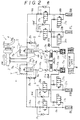
- a throttle valve apparatus 6a is connected to the conduit 5a.
- a check valve 7a is connected in parallel with the throttle valve apparatus 6a. It permits fluid to flow from the wheel cylinder side toward the master cylinder side. Also, it prevents fluid from flowing from the master cylinder side toward the wheel cylinder side.
- the throttle valve apparatus 6a and the check valve 7a are formed integrally with each other in this embodiment.
- the details of the throttle -check valve apparatus T are shown in Fig. 3.
- the valve apparatus 6a is connected through a conduit 16a to an inlet valve 17a and a conduit 18a to a wheel cylinder of the left rear wheel RL.
- a check valve 19a is connected in parallel with the inlet valve 17a. It permits fluid to flow from the wheel cylinder side toward the master cylinder side, while it prevents fluid from flowing from the master cylinder side toward the wheel cylinder side.
- outlet valves 23a and 24a are connected to the wheel cylinders of the right front wheel FR and the left rear wheel RL, and also to a hydraulic low-pressure reservoir 25a.
- the low-pressure reservoir 25a has a well- known construction.
- a piston is slidably fitted into a casing which is urged upward by a weak spring.
- a reservoir chamber is formed above the piston in it.
- a fluid pressure pump 10 is connected in common with another hydraulic low -pressure reservoir 25b.
- the fluid pressure pump 10 has a well-known construction.
- An eccentric cam mechanism 12 is driven by an electric motor 11 in the fluid pressure pump 10. Two pistons are driven backward and forward, and positive pressure and negative pressure are alternately generated in the fluid pressure chambers formed at both sides of the pistons.
- a check valve 15a is connected to the fluid pressure chamber. Brake fluid is withdrawn from the reservoir 25a.
- the fluid pressure chamber is connected through a check valve 13a to a dumper 14a.
- the dumper 14a has a well-known construction. Fluid pressure discharged through the check valve 13a is transmitted to the conduit 16a through the dumper 14a and a check valve 8a.
- the throttle valve apparatus 6a is connected through a conduit 9a to the dumper 14a.
- the check valve 8a is connected in a conduit divided from the conduit 9a. It permits fluid to flow from the dumper 14a side toward the master cylinder side, while it prevents fluid from flowing from the master cylinder side toward the dumper 14a side.
- the inlet valves 17a and 20a and the outlet valves 23a and 24a are electro-magnetic change over valves. They have solenoid portions. When the solenoid portions are not energized, they take communicating positions or cut-off positions as shown in Fig. 2. When the solenoid portions are energized, they change over to take the opposite cut-off positions or communicating positions.
- the throttle valve apparatus 6a When the fluid pressure of the conduit 9a becomes higher than a predetermined value, the throttle valve apparatus 6a is changed to take a throttling position, from the communicating position.
- a stepped hole 31a is formed in a housing 31.
- a sleeve 32 provided with seal rings 33 and 34 is fitted into the stepped hole.
- a stepped hole is formed in the sleeve 32.
- An annular groove is formed in a smaller diameter portion of the stepped hole and a seal ring 35 is fitted into the annular groove.
- a smaller diameter portion 36a of a fluid pressure drive piston 36 is slidably fitted into the seal ring 35. Further, a seal ring 37 is fitted into a larger diameter portion of the piston 36. The piston 36 is urged leftward by a spring 38 and it contacts normally with the sleeve 32.
- a plug member 40 provided with a seal member 41 is fitted into the sleeve 32 at the left opening end of the housing 31.
- a nut 42 is screwed into the left opening end of the housing 31 and it fastens the plug member 40.
- a valve chamber V is formed in the inside hole of the sleeve 32.
- a valve body 43 is urged by a spring 47 in the valve chamber V . It is separated from a stepped portion 61 of the sleeve 32 by the smaller diameter portion 36a of the fluid pressure drive piston 36 as shown in Fig. 3.
- a cut-out 43a is formed at an end portion of the valve body 43. When it contacts with the stepped portion 61, a throttle path is formed between the valve chamber V and the conduit 16a side. Further, paths 44, 45 and 46 are formed in the housing 31. They are connected to the conduits 5a, 16a and 9a, respectively.
- a fluid pressure chamber 62 is formed between the fluid pressure drive piston 36 and the sleeve 32. It communicates through the conduit 9a and the dumper 14a to the output side of the fluid pressure pump 10.
- a predetermined pressure to change over into the throttling position of the throttling valve apparatus 6a is determined by a spring force of the spring 38 urging the fluid pressure drive piston 36, and the fluid pressure receiving area of the fluid pressure drive piston 36.
- Both of the front wheels FR and FL are independently controlled of the other wheels by the control unit E.
- the control unit E judges that braking should be decreased, (for the facilitation of the understanding, the skid conditions of the front wheels FR and FL are assumed to be the same as each other)
- the solenoid portions of the inlet valves 20a and 20b are energized.
- the conduit 22a side and the conduit 16a side and the conduit 22b side and the conduit 16b side are interrupted from each other.
- the solenoid portions of the outlet valves 24a and 24b are energized to make the conduit 22a, 22b side and the conduit 26a, 26b side communicate with each other.
- the brake fluid is discharged through the outlet valves 24a and 24b into the hydraulic reservoir 25a, 25b from the wheel cylinders of the right front wheel FR and left front wheel FL.
- the fluid pressure pump 10 starts to be driven and so at once the brake fluid is drawn from the hydraulic reservoirs 25a and 25b.
- the pressurized fluid flows through the check valves 13a, 13b into the dumpers 14a and 14b.
- the pulsating pressure of the fluid pressure pump 10 is greatly decreased and then it is transmitted to the fluid pressure supply conduits 16a, 16b connecting the throttling valve apparatus 6a, 6b with inlet valves 20a and 20b.
- the fluid pressure from the master cylinder side is transmitted through the throttle into the conduit 16a, 16b side.
- the brake can be rapidly applied. Since the dumper 14a, 14b and the throttle valve apparatus 6a, 6b are arranged in this manner, the hammering sensation due to the increasing pressure acceleration of the brake fluid pressure, when the brake is reapplied during the anti-skid control operation, can be greatly decreased or almost cancelled. Thus, the vehicle vibration can be greatly decreased or it can be almost cancelled.
- Input signals are formed in a judge part of the control unit E which has a well-known circuit construction. It includes a slip signal generator, a differentiator, an approximate vehicle speed forming circuit, etc, and judges the skid conditions of the wheels on the basis of the outputs of the wheel speed sensors.
- Output signals (EVFL), (EVRR), (EVRL) and (EVFR) are drive signals (EV) for driving valves to hold the brake fluid pressures of the wheels FL, RR, RL and FR, respectively.
- output signals (AV Rear) and (EV Rear) are drive signals (AV) for driving valves to decrease and hold both of the brake fluid pressures of the rear wheels RL and RR, respectively.
- the control signals AVFL and EVFL are supplied to a signal selection circuit 50 a . Further, a previous cycle control signal of the left front wheel (FL) and another factor representing any control condition of the wheel FL are supplied to the signal selection circuit 50 a .
- the previous cycle control signal represents a control signal previous directly to the present control signal. It is obtained from the memory of the computer in the control unit E that the AV signal or EV signal has been previously generated from the wheel FL.
- Various signals can be considered as the other factor in accordance with the skid condition of the wheel FL. For example, when the signal selection circuit 50 a receives a control signal AVFL, it generates a AV control signal and/or EV control signal by its logic.
- Such an output is supplied to a first select-low (diagonal) circuit 51 a .
- a select-low control is effected between the front wheel FL and the rear wheel RR connected diagonally to the front wheel FL, by the first select-low circuit 51 a .
- the AVRR and EVRR signals are further supplied to the first select-low circuit 51 a for the above-mentioned select-low.
- Such an output is supplied to another first select-low (diagonal) circuit 51 b .
- a select-low control is effected between the front wheel FR and the rear wheel RL connected diagonally to the front wheel FR, by the other first select-low circuit 51 b .
- the AVRL and EVRL signals are further supplied to the select-low circuit 51 b for the above-mentioned select-low.
- the AV time namely the brake decreasing time is determined on the basis of the signals representing the present control condition of the vehicle such as the vehicle speed, vehicle deceleration, the number of the control cycles and any other factor, by a predetermined calculation of the time-setting circuits 55 a and 55 b , respectively.
- the valve driving signals (AVRR), (EVRR) and (AVRL), (EVRL) are generated from the time-setting circuits 55 a and 55 b for the right and left rear wheels RR and RL, respectively.
- the time of the valve drive signal (AVRR) or (AVRL) is determined by the time-setting circuit 55 a , 55 b .
- the time-setting circuit 55 a , 55 b determines what percentage of the selected output AV is used as the valve drive signal AV for the rear wheel.
- the ratio of the brake decreasing time to the brake holding time is varied for the percentages.
- the solenoid portions of the change-over valves are alternately and intermittently energized.
- the so-called “stepwise decreasing” is effected.
- the step height of the stepwise decreasing is set in the time-setting circuits 55a and 55b.
- the select-low circuit 51 a , 51 b or the select-low circuit 53 are, or is, put into the operative state in response to the signals supplied to the safety circuit 52.
- the fluid pressure control method for the anti-skid control apparatus for the rear wheels RL and RR is effected in the above manner. Next, operation of the fluid pressure control method will be described.
- (A) represents the wheel speeds VFR, VFL, VRR and VRL of the right front wheel, left front wheel, right rear wheel and left rear wheel, respectively, after depressing the brake pedal.
- (B) shows a valve change-over drive signal for the right front change-over valves 20a, 24a, the control signal representing the judge result of the right front wheel FR and the brake fluid pressure PFR obtained on the basis of the control signal of FR.
- the AV signal becomes EV signal, and it continues by time t 4 .
- the level is zero till time t 5 .
- the valve is driven by the control logic L 2 .
- a pulse signal of constant duty cycle is generated by the software in the control logic L 2 .
- the duty cycle is changed. Rectangular pulses, the width of which become shorter with time, are generated.
- the brake fluid pressure PFR applied to the wheel cylinder of the right front wheel FR changes as shown in Fig. 4(B).
- the pressure PFR increases during times t 0 and t 1 .
- the brake is maintained for the time between times t 1 and t 2 and it decreases during the time between times t 2 and t 3 . Also the brake fluid pressure is maintained during times t 3 and t 4 .
- the change over valve is operated in accordance with the logical construction L 2 of the control unit.
- the fluid pressure is setpwisely increased by the above described pulses which consist of the two pulses of constant width and the pulses of the changing duty cycle.
- the holding times of the pulses of changing duty cycle are relatively long and they are shortened stepwisely with time.
- the control signal FR becomes again level 1/2 at time t 5 .
- the valve drive signal is unchanged. It becomes level 1 at time t 6 .
- the fluid pressure PFR is decreased. It becomes level 1/2 at time t 7 and the level continues till time t 8 .
- the fluid pressure PFR is maintained at constant during the time. It becomes level zero during the time between time t 8 and t 9 .
- the brake fluid pressure PFR is controlled as in the above first control cycle. It becomes again level 1/2 at time t 9 and it is maintained till time t 10 and it becomes level 1. Then it is lowered to level 1/2 at time t 11 . Next, it continues till time t 12 and it becomes level zero.
- the brake fluid pressure control is effected in the same manner as the second control cycle by the logic L 2 of the control unit E.
- the fluid pressure PFR of the front wheel FR is controlled independently of the other front wheel and rear wheels.
- the brake fluid pressure PFL of the left front wheel FL is controlled in the same manner as the brake fluid pressure PFR of the right front wheel FR.
- the control signal FL becomes 1/2 at time t 1 ' and it becomes 1 at time t 2 '. It becomes again 1/2 at time t 3 ' and it continues till time t 4 '.
- the brake fluid pressure of the left front wheel changes as shown by PFL.
- the wheel cylinder pressure of FL is stepwisely increased by the pulse drive for the predetermined time, by the logic L 1 of the control unit E.
- the brake decreasing signal AV of the left front wheel FL is continuous, the brake of the right rear wheel RR is decreased for the set-time of the time-setting circuit 55a as shown by the two fine lines.
- the fluid pressure of the right rear wheel RR is stepwisely decreased, although it is not clearly shown.
- the fluid pressure of the front wheel FL is decreased till time t 3 as shown by PRR.
- the change amount of the fluid pressure decrease during the time t 2 ' and t 3 ' is smaller than that of the front wheel FL.
- the inclination of the brake decreasing pressure as shown is smaller.
- the brake fluid decrease is smaller than that of the left front wheel FL.
- the valve change-over signal RL becomes 1.
- the signal of level 1 as above described is generated from the right front wheel FR diagonally connected to the rear wheel RL.
- the level becomes 1 by the select-low control.
- the duration of the control signal AV of the front wheel FR is not entirely used, but it is used only for the time set in the time-setting circuit 55b to decrease the brake.
- the brake fluid pressure is stepwisely decreased. Accordingly the decreasing amount of the brake fluid pressure is smaller in comparison with that of the front wheel FR.
- the select-low control is not effected by the diagonal select-low circuit 51a, 51b, but it is effected by the left-right select-low circuit 53.
- the braking distance can be much shortened.
- the time of the brake decreasing operation is longer or when the change over valve for the front wheel is locked at the brake decreasing position, the select-low between the front and rear wheels is stopped and so the select-low between the rear wheels is effected.
- the braking force can be secured by the rear wheels. No -brake is prevented.
- the holding time is longer than the predetermined time, that holds true.
- the diagonal select-low between the front and rear wheels is effected again by the select-low circuits 51a and 51b. Accordingly, the brake fluid pressure is changed in the manner shown in Fig. 5.
- the fluid pressure control valve for the rear wheel receives only the holding instruction or the increasing instruction. In such a manner, the same effect as the alteration of the preferential order between the select-low controls can be obtained.
- the select-low circuit 53' is selected by the control mode selecting circuit 52' and so the control is changed over into the select -low control between the rear wheels.
- the second embodiment has the effect that the braking distance can be further shortened when the relatively large load is applied to the rear wheels, in addition to the effect of the first embodiment.
- the stepwise decreasing signal is obtained from the time -setting circuits 55a, 55b, using the output signal AV supplied from the select-low circuits 51a, 51b.
- the time-setting circuits 55a, 55b may be so designed as to generate the valve change over signal which decreases continuously the brake fluid for one time period and holds the braking force for another time period.
- this invention is applied to the so-called “circulation type anti-skid apparatus” in which the change-over valve (fluid pressure control valve or solenoid valve) is connected in series with the conventional brake conduits and the brake fluid pressure to the wheel cylinder is directly increased and decreased.
- this invention may be applied to the so-called “volume-variable type anti -skid apparatus” in which a hydraulic pressure unit is connected in parallel with the conventional brake conduits and its volume is increased and decreased to increase and decrease the brake fluid pressure to the wheel cylinder.
Landscapes
- Engineering & Computer Science (AREA)
- Transportation (AREA)
- Mechanical Engineering (AREA)
- Physics & Mathematics (AREA)
- Fluid Mechanics (AREA)
- Regulating Braking Force (AREA)
Claims (7)
- Verfahren zur Fluiddruckregelung einer Antiblockierregelvorrichtung für ein Fahrzeug, wobei die Antiblockierregelvorrichtung aufweist:einen Tandemhauptzylinder (1),Radzylinder, die den jeweiligen Rädern (RL, FR, FL, RR) zugeordnet sind,Radgeschwindigkeitssensoren, die den jeweiligen Rädern (RL, FR, FL, RR) zugeordnet sind,eine Regeleinheit (E), welche die Ausgangswerte der Radgeschwindigkeitssensoren empfängt, um Rutschzustände der jeweiligen Räder festzustellen bzw. zu beurteilen, undDruckregelventile (17a, 17b, 20a, 20b, 23a, 23b, 24a, 24b), welche zwischen dem Tandemhauptzylinder und den jeweiligen Radzylindern angeordnet sind und welche Anweisungen von der Regeleinheit (E) zum Regeln des Bremsfluiddruckes der jeweiligen Radzylinder erhalten,
wobei das Verfahren die Schritte aufweist, daß die Regeleinheit (E) so betreibbar ist, daß sie Bremsennachlaßanweisungen und Bremsenhalteanweisungen den Fluiddruckregelventilen (20a, 20b, 24a, 24b) für die Vorderräder unabhängig zuführt, die anderen Fluiddruckregelventile für die Hinterräder (RL, RR) durch diagonale "Niedrigwahl"-Schritte (51a, 51b) zwischen den Rutschzuständen jedes der Hinterräder (RL, RR) und dem entsprechenden, diagonal damit verbundenen Vorderrad (FR, FL), regelt, dadurch gekennzeichnet, daßdann, wenn die Bremsennachlaßanweisung oder die Bremsenhalteanweisung dem Fluiddruckregelventil (17a, 17b, 23a, 23b) für eines der Hinterräder zugeführt wird, und zwar auf Basis des Regelsignales, welches den Rutsch- bzw. Schlupfzustand des jeweils diagonal verbundenen Vorderrades wiedergibt, das Regelsignal, wiches den Rutschzustand des jeweiligen Vorderrades wiedergibt, für das Fluiddruckregelventil (17a, 17b, 23a, 23b) für das betreffende Hinterrad verwendet wird, und zwar mit einer verminderten Rate unter Ansprechen auf den Regelzustand des jeweiligen Vorderrades und/oder des gebremsten Zustandes des Fahrzeuges. - Fluiddruckregelverfahren nach Anspruch 1, wobei die Regeleinheit (E) so betreibbar ist, daß sie die anderen Fluiddruckregelventile (17a, 17b, 23a, 23b) für die hinteren Räder durch einen links-rechts "Niedrigauswahl"-Schritt (53) zwischen den Rutschzuständen der Hinterräder regelt, wenn die Zeitdauer der Bremsennachlaßanweisung länger als eine vorbestimmte Zeit dauert, oder wenn der Radgeschwindigkeitssensor für das Vorderrad anomal wird.
- Fluiddruckregelverfahren für eine Antiblockiereinrichtung eines Fahrzeuges, wobei die Antiblockierregeleinrichtung aufweist:einen Tandemhauptzylinder (1)Radzylinder, die den jeweiligen Rädern (RL, FR, FL, RR) zugeordnet sind,Radgeschwindigkeitssensoren, die den jeweiligen Rädern zugeordnet sind (RL, FR, FL, RR),eine Regeleinheit (E), die Ausgangswerte der Radgeschwindigkeitssensoren empfängt, um Rutschzustände der jeweiligen Räder zu beurteilen, undFluiddruckregelventile (17a, 17b, 20a, 20b, 23a, 23b, 24a, 24b), die zwischen dem Tandemhauptzylinder (1) und den jeweiligen Radzylindern angeordnet sind und welche Anweisungen aus der Regeleinheit (E) empfangen, um die Bremsfluiddrücke der jeweiligen Radzylinder zu regeln,
wobei das Verfahren die Schritte aufweist, daß die Regeleinheit (E) so betreibbar ist, daß sie Bremsnachlaßanweisungen, Bremshalteanweisungen und Bremssteigerungsanweisungen unabhängig den Fluiddruckregelventilen (20a, 20b, 24a, 24b) für die Vorderräder zuführt, und die anderen der Fluiddruckregelventile (17a, 17b, 23a, 23b) für die Hinterräder durch diagonale "Niedrigauswahl"-Schritte (51a, 51b) zwischen den Rutschzuständen bzw. Blockierzuständen jedes der Hinterräder (RL, RR) und des jeweiligen diagonal damit verbundenen Vorderrades (FL, FR) regelt,
dadurch gekennzeichnet, daßdann, wenn die Bremsennachlaßanweisung, die Bremshalteanweisung oder die Bremssteigerungsanweisung dem Fluiddruckregelventil (17a, 17b, 23a, 23b) für eines der Hinterräder zugeführt wird, und zwar auf Basis des Steuersignals, welches den Rutsch- bzw. Blockierzustand des jeweils diagonal zugeordneten Vorderrades wiedergibt, das Steuersignal, welches den Rutsch- bzw. Blockierzustand des jeweiligen Vorderrades wiedergibt, für das Fluiddruckregelventil (17a, 17b, 23a, 23b) des betreffenden Hinterrades verwendet wird, und zwar mit einer reduzierten Rate unter Ansprechen auf den Regelzustand des entsprechenden Vorderrades, den Bremszustand des Fahrzeuges und die Stabilität der Hinterräder. - Verfahren zur Fluiddruckregelung nach Anspruch 3, wobei die Steuereinheit (E) so betreibbar ist, daß sie die anderen Fluiddruckregelventile (17a, 17b, 23a, 23b) für die Hinterräder durch einen links-rechts "Niedrigwahl"-Schritt (53) zwischen den Rutschzuständen der Hinterräder regelt, wenn die Zeitdauer der Bremsennachlaßanweisung oder des Bremsenhalteanweisung länger andauert als eine vorbestimmte Zeit, oder wenn der Radgeschwindigkeitssensor für das Vorderrad anomal wird, oder wenn die Stabilität der Hinterräder länger als eine zweite vorbestimmte Zeit kontinuierlich erreicht worden ist.
- Fluiddruckregelverfahren nach Anspruch 4, wobei das Regelsignal, welches für die Wiedergabe des Rutschzustandes des Vorderrades verwendet wird, die Bremshaltanweisung oder die Bremsverstärkungsanweisung ist, welche vorliegt, wenn die Stabilität der Hinterräder kontinuierlich für eine dritte vorbestimmte Zeitdauer erhalten wird, die kürzer ist als die zweite vorbestimmte Zeitdauer oder wenn die Stabilität der Hinterräder in der Aufsummierung für die dritte vorbestimmte Zeitdauer erhalten wird.
- Verfahren zur Fluiddruckregelung nach Anspruch 4, bei welchem die Stabilität dadurch gegeben ist, daß der Schlupfwert oder das Schlupfverhältnis eines der Hinterräder kleiner ist als ein vorbestimmter Wert.
- Fluiddruckregelverfahren für eine Antiblockierregelvorrichtung für ein Fahrzeug, wobei die Antiblockierregelvorrichtung aufweist:einen Tandemhauptzylinder (1),Radzylinder, die den jeweiligen Rädern (RL, FR, FL, RR) zugeordnet sind,Radgeschwindigkeitssensoren, die den jeweiligen Rädern (RL, FR, FL, RR) zugeordnet sind,eine Regeleinheit (E), die die Ausgangswerte der Radgeschwindigkeitssensoren empfängt, um Rutschzustände der jeweiligen Räder zu beurteilen bzw. festzustellen, und Fluiddruckregelventile (17a, 17b, 20a, 20b, 23a, 23b, 24a, 24b), die zwischen dem Tandemhauptzylinder (1) und den jeweiligen Radzylindern angeordnet sind, und die Anweisungen von der Regeleinheit (E) für das Regeln der Bremsfluiddrücke der jeweiligen Radzylinder empfangen,
wobei das Verfahren den Schritt aufweist, daß die Regeleinheit (E) so betreibbar ist, daß sie Bremsrücknahmeanweisungen und Bremshalteanweisungen unabhängig denjenigen der Fluiddruckregelventile (20a, 20b, 24a, 24b) für die Vorderräder zuführt, und die anderen Fluiddruckregelventile (17a, 17b, 23a, 23b) für die Hinterräder durch diagonale "Niedrigwahl"-Schritte (51a, 51b) zwischen den Rutschzuständen jedes der Hinterräder (RL, RR) und dem jeweiligen, diagonal damit verbundenen Vorderrad (FR, FL) regelt,
dadurch gekennzeichnet, daßdann, wenn die Geschwindigkeit des Fahrzeuges größer ist als ein vorbestimmter Wert, und wenn die Bremsrücknahmeanweisung oder die Bremshalteanweisung dem Fluiddruckregelventil (17a, 17b, 23a, 23b) für eines der Hinterräder zugeführt wird, und zwar auf Basis des Regelsignales, welches den Rutschzustand des jeweiligen diagonal zugeordneten Vorderrades wiedergibt, das Regelsignal, welches den erwähnten Rutschzustand des entsprechenden Vorderrades wiedergibt, für das Fluiddruckregelventil (17a, 17b, 23a, 23b) für das betreffende Hinterrad verwendet wird, und zwar mit einer reduzierten Rate, die auf den Regelzustand der jeweiligen Vorderräder und/oder den gebremsten Zustand des Fahrzeuges anspricht, und dann, wenn die Geschwindigkeit des Fahrzeuges niedriger ist als der vorbestimmte Wert, die Regeleinheit (E) die anderen Fluiddruckregelventile (17a, 17b, 23a, 23b) für die Hinterräder durch einen links-rechts "Niedrigwahl"-Schritt zwischen den Hinterrädern regelt.
Applications Claiming Priority (4)
| Application Number | Priority Date | Filing Date | Title |
|---|---|---|---|
| JP115921/94 | 1994-05-02 | ||
| JP11592194 | 1994-05-02 | ||
| JP272905/94 | 1994-10-12 | ||
| JP6272905A JP2895760B2 (ja) | 1994-05-02 | 1994-10-12 | 車両用アンチスキッド装置の液圧制御方法 |
Publications (2)
| Publication Number | Publication Date |
|---|---|
| EP0680862A1 EP0680862A1 (de) | 1995-11-08 |
| EP0680862B1 true EP0680862B1 (de) | 1999-03-24 |
Family
ID=26454347
Family Applications (1)
| Application Number | Title | Priority Date | Filing Date |
|---|---|---|---|
| EP95302981A Expired - Lifetime EP0680862B1 (de) | 1994-05-02 | 1995-05-02 | Bremsdruckregulation in Blockierschutz-Regeleinrichtung für Kraftfahrzeuge |
Country Status (4)
| Country | Link |
|---|---|
| US (1) | US5570936A (de) |
| EP (1) | EP0680862B1 (de) |
| JP (1) | JP2895760B2 (de) |
| DE (2) | DE69508459T2 (de) |
Families Citing this family (6)
| Publication number | Priority date | Publication date | Assignee | Title |
|---|---|---|---|---|
| JPH08188138A (ja) * | 1995-01-13 | 1996-07-23 | Nissan Motor Co Ltd | アンチスキッド制御装置 |
| JPH09290735A (ja) * | 1996-04-30 | 1997-11-11 | Toyota Motor Corp | ブレーキシステム |
| JPH1178842A (ja) * | 1997-09-09 | 1999-03-23 | Unisia Jecs Corp | ブレーキ制御装置 |
| DE102008042534A1 (de) * | 2007-10-12 | 2009-04-16 | Advics Co., Ltd., Kariya | Antiblockiersteuervorrichtung und Automatikbremssteuervorrichtung |
| JP2019039541A (ja) * | 2017-08-29 | 2019-03-14 | 日本電産トーソク株式会社 | 油圧制御装置 |
| JP2019039542A (ja) * | 2017-08-29 | 2019-03-14 | 日本電産トーソク株式会社 | 油圧制御装置 |
Family Cites Families (6)
| Publication number | Priority date | Publication date | Assignee | Title |
|---|---|---|---|---|
| DE3301948A1 (de) * | 1983-01-21 | 1984-07-26 | Alfred Teves Gmbh, 6000 Frankfurt | Verfahren und vorrichtung zur steuerung der bremskraftverteilung |
| DE3306611A1 (de) * | 1983-02-25 | 1984-08-30 | Alfred Teves Gmbh, 6000 Frankfurt | Verfahren und vorrichtung zur steuerung der bremskraftverteilung |
| DE3733801A1 (de) * | 1987-09-21 | 1989-03-30 | Wabco Westinghouse Fahrzeug | Antiblockiersystem fuer fahrzeuge |
| DE3934307C3 (de) * | 1989-10-13 | 1998-10-01 | Lucas Ind Plc | Verfahren zum Steuern des Bremsdruckes in einer blockiergeschützten Bremsanlage |
| DE4107278A1 (de) * | 1991-03-07 | 1992-09-10 | Bosch Gmbh Robert | Antiblockierregelsystem |
| DE4116373A1 (de) * | 1991-05-18 | 1992-11-19 | Teves Gmbh Alfred | Schaltungsanordnung zur steuerung des bremsdruckaufbaus fuer eine bremsanlage mit blockierschutzregelung |
-
1994
- 1994-10-12 JP JP6272905A patent/JP2895760B2/ja not_active Expired - Fee Related
-
1995
- 1995-05-01 US US08/432,963 patent/US5570936A/en not_active Expired - Fee Related
- 1995-05-02 DE DE69508459T patent/DE69508459T2/de not_active Expired - Fee Related
- 1995-05-02 EP EP95302981A patent/EP0680862B1/de not_active Expired - Lifetime
- 1995-05-02 DE DE0680862T patent/DE680862T1/de active Pending
Also Published As
| Publication number | Publication date |
|---|---|
| JP2895760B2 (ja) | 1999-05-24 |
| EP0680862A1 (de) | 1995-11-08 |
| US5570936A (en) | 1996-11-05 |
| DE680862T1 (de) | 1996-03-14 |
| DE69508459D1 (de) | 1999-04-29 |
| DE69508459T2 (de) | 1999-10-28 |
| JPH08104220A (ja) | 1996-04-23 |
Similar Documents
| Publication | Publication Date | Title |
|---|---|---|
| US4453782A (en) | Brake fluid pressure control apparatus in skid control system | |
| US5026127A (en) | Fluid pressure brake control apparatus for a vehicle | |
| JPH0662079B2 (ja) | 自動車用ブレーキシステム | |
| US5011235A (en) | Anti-skid control apparatus for a vehicle braking system | |
| JPH0624912B2 (ja) | 車両のアンチロツク制御方法 | |
| US6595600B2 (en) | Front-rear braking force distribution control system | |
| US4793662A (en) | Anti-skid control apparatus for a vehicle braking system | |
| US4611859A (en) | Anti-skid braking apparatus for vehicles | |
| US4776644A (en) | Anti-skid control apparatus for a vehicle braking system | |
| US4753493A (en) | Anti-skid control apparatus for a vehicle braking system | |
| US5868473A (en) | Hydrulic braking pressure control system for an automotive vehicle | |
| US5788345A (en) | Anti-skid control device | |
| US6012782A (en) | Apparatus for controlling differences in braking torque between left and right wheels of vehicle | |
| US5570936A (en) | Fluid pressure control method of an anti-skid control apparatus for vehicle | |
| US4805967A (en) | Anti-skid control apparatus for a vehicle braking system | |
| US5150950A (en) | Anti-skid brake control method | |
| US4872729A (en) | Anti-skid control apparatus for a vehicle braking system | |
| US4854649A (en) | Anti-skid control apparatus for a vehicle braking system | |
| JPH04231247A (ja) | ブレーキ圧制御装置 | |
| US5700069A (en) | Anti-skid control system for an automotive vehicle | |
| JPH10138895A (ja) | 車両用ブレーキ装置 | |
| JP3554569B2 (ja) | 制動力配分制御装置 | |
| US5178440A (en) | Antiskid brake control method | |
| JP4449117B2 (ja) | 制動力配分制御装置 | |
| US4971401A (en) | Anti-skid control apparatus for braking system |
Legal Events
| Date | Code | Title | Description |
|---|---|---|---|
| PUAI | Public reference made under article 153(3) epc to a published international application that has entered the european phase |
Free format text: ORIGINAL CODE: 0009012 |
|
| AK | Designated contracting states |
Kind code of ref document: A1 Designated state(s): DE GB |
|
| DET | De: translation of patent claims | ||
| 17P | Request for examination filed |
Effective date: 19960426 |
|
| 17Q | First examination report despatched |
Effective date: 19970509 |
|
| GRAG | Despatch of communication of intention to grant |
Free format text: ORIGINAL CODE: EPIDOS AGRA |
|
| GRAG | Despatch of communication of intention to grant |
Free format text: ORIGINAL CODE: EPIDOS AGRA |
|
| GRAG | Despatch of communication of intention to grant |
Free format text: ORIGINAL CODE: EPIDOS AGRA |
|
| GRAH | Despatch of communication of intention to grant a patent |
Free format text: ORIGINAL CODE: EPIDOS IGRA |
|
| GRAH | Despatch of communication of intention to grant a patent |
Free format text: ORIGINAL CODE: EPIDOS IGRA |
|
| GRAA | (expected) grant |
Free format text: ORIGINAL CODE: 0009210 |
|
| AK | Designated contracting states |
Kind code of ref document: B1 Designated state(s): DE GB |
|
| REF | Corresponds to: |
Ref document number: 69508459 Country of ref document: DE Date of ref document: 19990429 |
|
| RAP2 | Party data changed (patent owner data changed or rights of a patent transferred) |
Owner name: NIPPON ABS LIMITED |
|
| PLBE | No opposition filed within time limit |
Free format text: ORIGINAL CODE: 0009261 |
|
| STAA | Information on the status of an ep patent application or granted ep patent |
Free format text: STATUS: NO OPPOSITION FILED WITHIN TIME LIMIT |
|
| 26N | No opposition filed | ||
| REG | Reference to a national code |
Ref country code: GB Ref legal event code: 732E |
|
| PGFP | Annual fee paid to national office [announced via postgrant information from national office to epo] |
Ref country code: DE Payment date: 20010423 Year of fee payment: 7 |
|
| PGFP | Annual fee paid to national office [announced via postgrant information from national office to epo] |
Ref country code: GB Payment date: 20010502 Year of fee payment: 7 |
|
| REG | Reference to a national code |
Ref country code: GB Ref legal event code: IF02 |
|
| PG25 | Lapsed in a contracting state [announced via postgrant information from national office to epo] |
Ref country code: GB Free format text: LAPSE BECAUSE OF NON-PAYMENT OF DUE FEES Effective date: 20020502 |
|
| PG25 | Lapsed in a contracting state [announced via postgrant information from national office to epo] |
Ref country code: DE Free format text: LAPSE BECAUSE OF NON-PAYMENT OF DUE FEES Effective date: 20021203 |
|
| GBPC | Gb: european patent ceased through non-payment of renewal fee |
Effective date: 20020502 |